Patrick F. Dunn, Measurement, Data Analysis, and Sensor Fundamentals for Engineering and Science, 2nd Edition
Подождите немного. Документ загружается.


26 Measurement and Data Analysis for Engineering and Science
FIGURE 2.6
Parallel R, C, and L circuit configurations.
Thus, when in parallel, capacitances add, and the reciprocals of resistances
and inductances add.
Example Problem 2.2
Statement: Determine the total equivalent resistance, R
T
, and total equivalent
capacitance, C
T
, for the respective resistance and capacitance circuits shown in Figure
2.7.
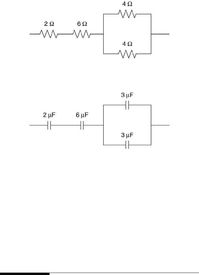
Solution: For the two resistors in parallel, the equivalent resistance, R
a
, is
1
R
a
=
1
4
+
1
4
= 2 Ω.
The two other resistors are in series with R
a
, so R
T
= R
a
+ 2 + 6 = 10 Ω.
For the two capacitors in parallel, the equivalent capacitance, C
b
, is C
b
= 3 + 3 =
6 µF . This is in series with the two other capacitors, which implies that
1
C
T
=
1
2
+
1
3
+
1
C
b
=
1
2
+
1
3
+
1
6
= 1.
So, C
T
=1 µF.
To aid further with circuit analysis, two laws developed by G. R. Kirch-
hoff (1824 - 1887) can be used. Kirchhoff’s current (or first) law, which
is conservation of charge, states that at any junction (node) in a circuit, the
current flowing into the junction must equal the current flowing out of it,
which implies that
X
node
I
in
=
X
node
I
out
. (2.15)
A node in a circuit is a point where two or more circuit elements meet.
Kirchhoff’s voltage (or second) law, which is conservation of energy,
says that around any loop in a circuit, the sum of the potential differences
equals zero, which gives
Electronics 27
FIGURE 2.7
Resistor and capacitor circuits.
X
i,cl.loop
V
i
= 0. (2.16)
A loop is a closed path that goes from one node in a circuit back to it-
self without passing through any intermediate node more than once. Any
consistent sign convention will work when applying Kirchhoff’s laws to a
circuit. Armed with this information, some important DC circuits can be
examined now.
2.5 Elementary DC Circuit Analysis
In DC circuits, current is steady in time. Thus, there is no inductance, even
if an inductor is present. An actual inductor, however, has resistance. This
typically is on the order of 10 Ω. Often, an inductor’s resistance in a DC
circuit is neglected.
28 Measurement and Data Analysis for Engineering and Science
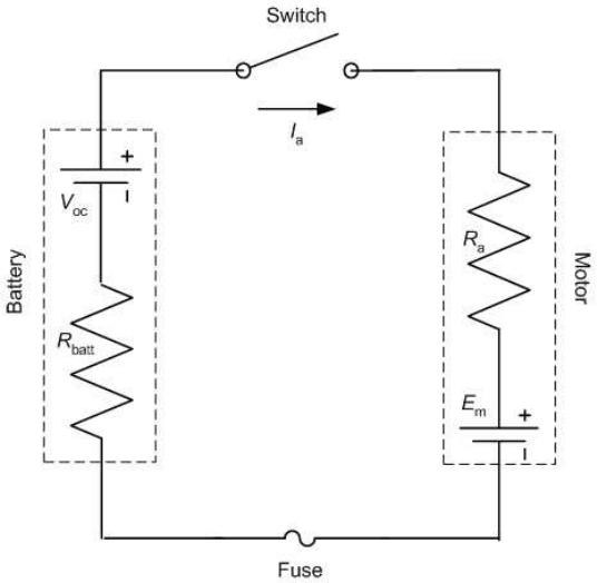
FIGURE 2.8
A battery and electric motor circuit.
The first elementary DC circuit to analyze is that of a DC electric motor
in series with a battery, as shown in Figure 2.8. Examine the battery first.
It has an internal resistance, R
batt
, and an open circuit voltage (potential
difference), V
oc
. R
batt
is the resistance and V
oc
the potential difference that
would be measured across the terminals of the battery if it were isolated
from the circuit by not being connected to it. However, when the battery is
placed in the circuit and the circuit switch is closed such that current, I
a
,
flows around the circuit, the situation for the battery changes. The measured
potential difference across the battery now is less because current flows
through the battery, effectively leading to a potential difference across R
batt
.
This yields
V
batt
= V
oc
− I
a
R
batt
, (2.17)
in which V
batt
represents the closed-circuit potential difference across the
battery. Similarly, the DC motor has an internal resistance, R
a
, which is
mainly across its armature. It also has an opposing potential difference,
E
m
, when operating with the battery connected to it. To summarize, V
oc
is
measured across the battery terminals when the switch is open, and V
batt
is
measured when the switch is closed.
Electronics 29
Now what is E
m
in terms of the known quantities? To answer this, apply
Kirchhoff’s second law around the circuit loop when the switch is closed.
Starting from the battery’s anode and moving in the direction of the current
around the loop, this gives
V
oc
− I
a
R
batt
− E
m
− I
a
R
a
= 0, (2.18)
which immediately leads to
E
m
= V
oc
− I
a
(R
batt
+ R
a
). (2.19)
This equation reveals a simple fact: the relatively high battery and motor
internal resistances lead to a decrease in the motor’s maximum potential
difference. This consequently results in a decrease in the motor’s power
output to a device, such as the propeller of a remotely piloted aircraft.
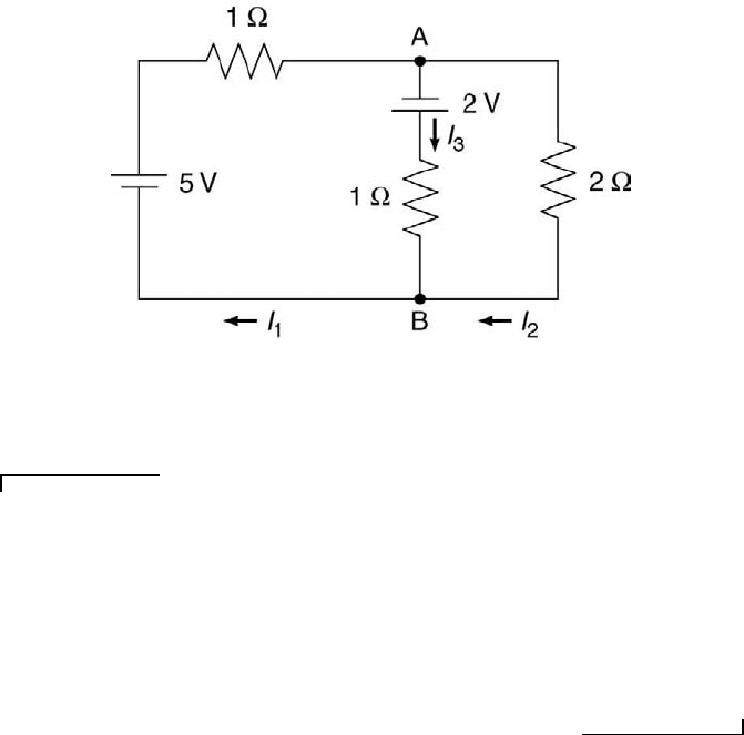
FIGURE 2.9
An electrical circuit.
Example Problem 2.3
Statement: For the electrical circuit shown in Figure 2.9, determine [a] the magni-
tude of the current in the branch between nodes A and B and [b] the direction of that
current.
Solution: Application of Kirchhoff’s second law to the left loop gives 5 V − (1 Ω)(I
1
A) + 2 V − (1 Ω)(I
3
A) = 0. Similar application to the right loop yields 2 V − (2
Ω)(I
2
A) + (1 Ω)(I
3
A) = 0. At node A, application of Kirchhoff’s first law implies I
1
− I
2
− I
3
= 0. These three expressions can be solved to yield I
1
= 3.8 A, I
2
= 0.6 A,
and I
3
= 3.2 A. Because I
3
is positive, the direction shown in Figure 2.9, from node A
to node B, is correct.
The second elementary direct-current circuit is a Wheatstone bridge.
The Wheatstone bridge is used in a variety of common instruments such
30 Measurement and Data Analysis for Engineering and Science
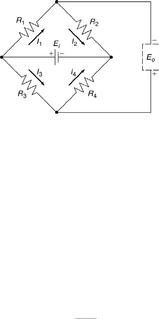
FIGURE 2.10
The Wheatstone bridge configuration.
as pressure transducers and hot-wire anemometers. Its circuit, shown in
Figure 2.10, consists of four resistors (R
1
through R
4
), each two comprising
a pair (R
1
and R
2
; R
3
and R
4
) in series that is connected to the other pair
in parallel, and a voltage source, E
i
, connected between the R
1
-R
3
and the
R
2
-R
4
nodes. The voltage output of the bridge, E
o
, is measured between the
R
1
-R
2
and the R
3
-R
4
nodes. E
o
is measured by an ideal voltmeter with an
infinite input impedance such that no current flows through the voltmeter.
An expression needs to be developed that relates the bridge’s output
voltage to its input voltage and the four resistances. There are four un-
knowns, I
1
through I
4
. This implies that four equations are needed to reach
the desired solution. Examination of the circuit reveals that there are four
closed loops for which four equations can be written by applying Kirchhoff’s
second law. The resulting four equations are
E
i
= I
1
R
1
+ I
2
R
2
, (2.20)
E
i
= I
3
R
3
+ I
4
R
4
, (2.21)
E
o
= I
4
R
4
− I
2
R
2
, (2.22)
and
E
o
= −I
3
R
3
+ I
1
R
1
. (2.23)
Kirchhoff’s first law leads to I
1
= I
2
and I
3
= I
4
, assuming no current flows
through the voltmeter. These two current relations can be used in Equations
2.20 and 2.21 to give
I
1
=
E
i
R
1
+ R
2
(2.24)

Electronics 31
and
I
3
=
E
i
R
3
+ R
4
. (2.25)
These two expressions can be substituted into Equation 2.23, yielding the
desired result
E
o
= E
i
R
1
R
1
+ R
2
−
R
3
R
3
+ R
4
. (2.26)
Equation 2.26 leads to some interesting features of the Wheatstone
bridge. When there is no voltage output from the bridge, the bridge is
considered to be balanced even if there is an input voltage present. This
immediately yields the balanced bridge equation
R
1
R
2
=
R
3
R
4
. (2.27)
This condition can be exploited to use the bridge to determine an unknown
resistance, say R
1
, by having two other resistances fixed, say R
2
and R
3
, and
varying R
4
until the balanced bridge condition is achieved. This is called
the null method. This method is used to determine the resistance of a
sensor which usually is located remotely from the remainder of the bridge.
An example is the hot-wire sensor of an anemometry system used in the
constant-current mode to measure local fluid temperature.
FIGURE 2.11
Cantilever beam with four strain gages.
The bridge can be used also in the deflection method to provide an
output voltage that is proportional to a change in resistance. Assume that
resistance R
1
is the resistance of a sensor, such as a fine wire or a strain gage.
The sensor is located remotely from the remainder of the bridge circuit in
an environment in which the temperature increases from some initial state.
Its resistance will change by an amount δR from R
1
to R
0
1
. Application of
Equation 2.26 yields
E
o
= E
i
"
R
0
1
R
0
1
+ R
2
−
R
3
R
3
+ R
4
#
. (2.28)

32 Measurement and Data Analysis for Engineering and Science
Further, if all the resistances are initially the same, where R
1
= R
2
= R
3
=
R
4
= R, then Equation 2.28 becomes
E
o
= E
i
δR/R
4 + 2δR/R
= E
i
f(δR/R). (2.29)
Thus, when using the null and deflection methods, the Wheatstone bridge
can be utilized to determine a resistance or a change in resistance.
One practical use of the Wheatstone bridge is in a force measurement
system. This system is comprised of a cantilever beam, rigidly supported on
one end, that is instrumented with four strain gages, two on top and two
on bottom, as shown in Figure 2.11. The strain gage is discussed further
in Chapter 3. A typical strain gage is shown in Figure 3.3 of that chapter.
The electric configuration is called a four-arm bridge. The system operates
by applying a known force, F , near the end of the beam along its centerline
and then measuring the output of the Wheatstone bridge formed by the
four strain gages. When a load is applied in the direction shown in Figure
2.11, the beam will deflect downward, giving rise to a tensile strain,
L
, on
the top of the beam and a compressive strain, −
L
, on the bottom of the
beam. Because a strain gage’s resistance increases with strain, δR ∼
L
, the
resistances of the two tensile strain gages will increase and those of the two
compressive strain gages will decrease. In general, following the notation in
Figure 2.11, for the applied load condition,
R
0
1
= R
1
+ δR
1
, (2.30)
R
0
4
= R
4
+ δR
4
, (2.31)
R
0
2
= R
2
− δR
2
, (2.32)
and
R
0
3
= R
3
− δR
3
. (2.33)
If all four gages are identical, where they are of the same pattern with
R
1
= R
2
= R
3
= R
4
= R, the two tensile resistances will increase by δR
and the two compressive ones will decrease by δR. For this case, Equation
2.28 simplifies to
E
o
= E
i
(δR/R). (2.34)
For a cantilever beam shown in Figure 2.11, the strain along the length of the
beam on its top side is proportional to the force applied at its end, F . Thus,
L
∼ F . If strain gages are aligned with this axis of strain, then δR ∼
L
, as
discussed in Section 3.3.2. Thus, the voltage output of this system, E
o
, is
linearly proportional to the applied force, F. Further, with this strain gage
configuration, variational temperature and torsional effects are compensated
for automatically. This is an inexpensive, simple yet elegant measurement
system that can be calibrated and used to determine unknown forces. This
Electronics 33
configuration is the basis of most force balances used for aerodynamic and
mechanical force measurements.
Example Problem 2.4
Statement: Referring to Figure 2.10, if R
1
= 1 Ω, R
2
= 3 Ω, and R
3
= 2 Ω,
determine [a] the value of R
4
such that the Wheatstone bridge is balanced, and [b] the
bridge’s output voltage under this condition.
Solution: Equation 2.27 specifies the relationship between resistances when the
bridge is balanced. Thus, R
4
= R
2
R
3
/R
1
= (3)(2)/1 = 6 Ω. Because the bridge is bal-
anced, its output voltage is zero. This can be verified by substituting the four resistance
values into Equation 2.26.
2.6 Elementary AC Circuit Analysis
As shown in Table 2.1, the expressions for the voltages and currents of AC
circuits containing resistors, capacitors, and inductors involve differentials
and integrals with respect to time. Expressions for V (t) and I(t) of AC
circuits can be obtained directly by solving the first-order and second-order
ordinary differential equations that govern their behavior. The differential
equation solutions for RC and RLC circuits subjected to step and sinusoidal
inputs are presented later in Chapter 4. At this point, a working knowledge
of AC circuits can be gained through some elementary considerations.
When capacitors and inductors are exposed to time-varying voltages in
AC circuits, they each create a reactance to the voltage. Reactance plus
resistance equals impedance. Symbolically, X + R = Z. Often an RLC
component is described by its impedance because it encompasses both re-
sistance and reactance. Impedance typically is considered generalized resis-
tance [2]. For DC circuit analysis, impedance is resistance because there is
no reactance. For this case, Z = R.
Voltages and currents in AC circuits usually do not vary simultaneously
in the same manner. An increase in voltage with time, for example, can be
followed by a corresponding increase in current at some later time. Such
changes of voltage and current in time are characterized best by using com-
plex number notation. This notation is described in more detail in Chapter
9.
Assume that the voltage, V (t), and the current, I(t), are represented
by the complex numbers V
o
e
iφ
and I
o
e
iφ
, respectively. Here e
iφ
is given by
Euler’s formula,
e
iφ
= cos φ + i sin φ, (2.35)
where i =
√
−1. In electrical engineering texts, j is used to denote
√
−1

34 Measurement and Data Analysis for Engineering and Science
because i is used for the current. Throughout this text, i symbolizes the
imaginary number. The real voltage and real current are obtained by multi-
plying each by the complex number representation e
iωt
and then taking the
real part, Re, of the resulting number. That is,
V (t) = Re(V e
iωt
) = Re(V ) cos ωt − Im(V ) sin ωt (2.36)
and
I(t) = Re(Ie
iωt
) = Re(I) cos ωt − Im(I) sin ωt, (2.37)
in which ω is the frequency in rad/s. The frequency in cycles/s is f, where
2πf = ω.
Expressions for capacitive and inductive reactances can be derived using
the voltage and current expressions given in Equations 2.36 and 2.37 [2]. For
a capacitor, I(t) = CdV (t)/dt. Differentiating Equation 2.36 with respect
to time yields the current across the capacitor,
I(t) = −V
o
Cω sin ωt = Re[V
o
e
i/ωC
1/iωC
]. (2.38)
The denominator of the real component is the capacitive reactance,
X
C
= 1/iωC. (2.39)
In other words, V (t) = I(t)X
C
.
For the inductor, V (t) = LdI(t)/dt. Differentiating Equation 2.37 with
respect to time yields the voltage across the inductor,
V (t) = −I
o
Lω sin ωt = Re[iωLI
o
e
i/ωC
]. (2.40)
The numerator of the real component is the inductive reactance,
X
C
= i/ωL. (2.41)
Simply put, V (t) = I(t)X
L
.
Because the resistances of capacitors and inductors are effectively zero,
their impedances equal the reactances. Further, the resistor has no reac-
tance, so its impedance is its resistance. Thus, Z
R
= R, Z
C
= 1/iωC, and
Z
L
= iωL.
Ohm’s law is still valid for AC circuits. It now can be written as V = ZI.
Also the rules for adding resistances apply to adding impedances, where for
impedances in series
Z
T
=
X
Z
i
, (2.42)
and for impedances in parallel
Z
T
= 1/
X
(
1
Z
i
). (2.43)
Electronics 35
Example Problem 2.5
Statement: An electrical circuit loop is comprised of a resistor, R, a voltage source,
E
o
, and a 1-µF capacitor, C, that can be added into the loop by a switch. When the
switch is closed, all three electrical components are in series. When the switch is open,
the loop has only the resistor and the voltage source in series. E
o
= 3 V and R = 2 Ω.
Determine the expression for the current as a function of time, I(t), immediately after
the switch is closed.
Solution: Applying Kirchhoff’s second law to the loop gives
RI(t) +
1
C
Z
I(t)dt = E
o
.
This equation can be differentiated with respect to time to yield
R
dI(t)
dt
+
I(t)
C
=
dE
o
dt
= 0,
because E
o
is a constant 3 V. This equation can be integrated to obtain the result
I(t) = C
1
e
−t/RC
, where C
1
is a constant. Now at t = 0 s, current flows through the
loop and equals E
o
/R. This implies that C
1
= 3/2 = 1.5 A. Thus, for the given values
of R and C, I(t) = 1.5e
−t/(2 × 10
−6
)
. This means that the current in the loop becomes
almost zero in approximately 10 µs after the switch is closed.
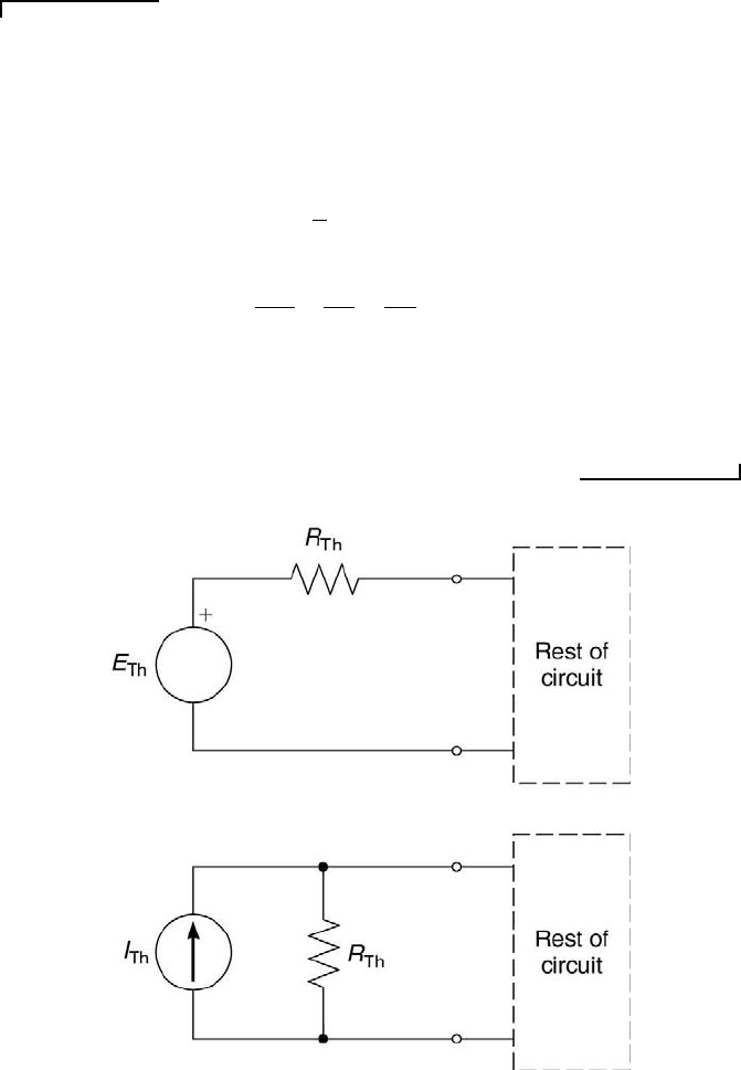
FIGURE 2.12
Th´evenin and Norton equivalent circuits.