Olkkonen J. (ed.) Discrete Wavelet Transforms - Theory and Applications
Подождите немного. Документ загружается.


switch on and off the controlled power devices, an LCL-filter, employed as a second-order low
pass filtering stage which allows the high freq uency ripple of the full-bridge output voltage to
be filtered out and a dc-side filtering stage, which can be implemented by means of one shunt
capacitor (first order) or a series inductance plus a shunt capacitor (second ord er).
dc
load or bus
R
L
2
1
R
3
L
2
R
1
C
3
LCL filter with damping
single-phase grid-connected power converter
PWM
current
controller
grid
synchronization
digital
controller
i
sin t
g
Reference
Current
Evaluation
v
g
gate circuit
IGBT
H-bridge
C
dc
+
dc-side
filter
i
*
v
g
acquisition
signal
conditioning
acquisition
signal
conditioning
i
g
Fig. 1. Three-phases three-wires grid connected dc/ac converter.
Depending on the application characteristics, the converter controller functionalities are
implemented using analog or digital circuitries and, in the second case, FPGAs, DPSs
and microcontrollers (μCs) allow more flexible and complex controllers to be designed
and implemented (Bueno et al., 2008; Koizumi et al., 2006; Kojabadi et al., 2006).
In case of grid-connected power converters, both inverters and controlled rectifiers
switching at relatively high frequencies (around 10 kHz), the main functionalities that
must be implemented are grid s ynchronizati on, evaluation of the reference for current
injection/consumption, grid side cu rrent control and pulse width modulation ( PWM)
(Kazmierkow ski et al., 2002). The grid synchronization block must generate, at least, a
reference signal sin ωt which must track properly the fundamental component of the grid
voltage v
g
. Depending on the application, i.e. distributed generation systems, the grid
frequency must be also measured in order to implement load sharing algorithms (Guerrero
et al., 2004). The evaluation of the instantaneous values of the reference current i
∗
is required
in order to determine the proper current which must flow from/to the electrical grid i
g
.
The implementation of this functionality depends on the applicati on and, hence, on the
implemented high level control functionalities such as reactive power requirements, harmonic
control, tolerance to grid disturbances or the maintenance of the dc-bus voltage. The obtained
values of i
∗
are applied to a current controller. This block must ensure that the grid side current
i
g
matches the reference ones i
∗
. Div erse approaches, such as hysteresis (Ho et al., 2009),
dead beat (Mohamed & El-Saadany, 2008), p ropor tional-integral (PI) control lers (Dannehl
et al., 2010), resonant controllers (Liserre et al., 2006), repetitive controllers (Weiss et al., 2004)
or inne r model controllers (Gabe et al., 2009), c an be found in literature for this purpose.
Finally, the control action must be applied to the gate circuitry of the H- bridge, where square
signal waveforms with variable width are required. In order to obtain these variable switching
patterns, diverse approaches can be also found. A detailed descriptio n of these techniques is
available in (Holmes & Lipo, 2003)
4. Synchronization subsystem in grid-connected power converters
Main approaches for s ynchronizati on of the power converter to the electrical grid are
zero crossing dete ction (Vainio & Ovaska, 1995; Valiviita, 1999) and phase locked loops
(PLLs) (El-Amawy & Mirbod, 1988; Freijedo et al., 2009). While the first one can be easily
implemented by means of analog circuitry, power system disturbances such as partial
discharges can result o n synchronization problems and an erroneous reference current i
∗
. Due
to this fact, the second approach and other based on digital signal processing techniques,
i.e. DFT (McGrath et al., 2005) and Kalman filter (Moreno et al., 2007), are preferred. A
common approach for implementation of PLLs includes a phase detection (PD) block, a
low-pass filtering stage and a voltage controlled oscillator (VCO). By applying the PD block,
the input signal v
g
is shifted in the frequency d omain to low frequency while other frequency
components of the input signal are shifted to higher frequencies. The obtained signal is
applied to a low-pass filtering stage for filtering out frequency components of the input signal
which must not be tracked. Once filtered out, the obtained signal is proportional to the phase
error of the input signal v
g
and the signal which is generated by the VCO and applied to
PD block. Due to the closed loop structure, and depending on the characteristics of the input
sig nal, the PD block and the low-pass filtering stage, the VC O will adjust the relative phase
and frequency of the generated signal in order to match the frequency component of v
g
to be
tracked.
Diverse approaches have been proposed in the literature in order to implement the
functional blocks in the previous paragraph but one of the most applied ones in case of
grid-connected power converters is based on the Park Transformation. Its general structure
for the synchronization of a single-phase grid-connected power converter is shown in Fig.
2. The gr id voltage is measured, digitized and applied to the software PLL by means of the
input port V
g
. This signal is employed to generate a vir tual quadrature component, denoted
as β, which allows the grid voltage, considered as α, to be represented as a phasor on a
stationary complex reference frame (Clarke Transformation), obtaining αβ components of
this single-phase voltage signal. The obtained instantaneo us values of this voltage phasor are
transformed again by applying the Park Transformation, w hich carries out a frequency shi ft
of the fundamental frequency track ed by the so ftware PLL. This al lows dq components of the
voltage phasor, obtained in a rotating reference frame, to be generated. Once the software
PLL is tracking the f undamental frequency properly (in phase), the q component of this
transformation should be equal to zero and, hence, the instantaneous phase generated by
the software PLL should be properly controlled. This is done by the Controller block. The
impact of po ssible amplitude variations, i.e. due to voltage sags, can be prevented by means
of a normalization block which g enerates dq compone nts in the range [-1,1]. The Controller
generates, as a result of its op eration and once the software PLL is operating properly, a
measure of the grid frequency. The instantaneous phase can be obtai ned by means of a d iscrete
integrator and, then, a sinusoidal output signal with unity amplitude and in-phas e with the
grid voltage signal can be generated by applying sin and cos functions to the measured
instantaneous phase. These trigonometric functions are required by the Park Transformation
in order to generate the dq compo nents .
219
Discrete Wavelet Transforms for Synchronization
of Power Converters Connected to Electrical Grids
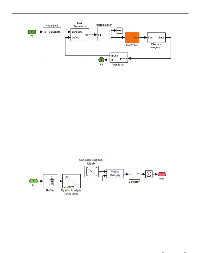
Fig. 2. Structure of software PLL for a single-phase grid-connected power co nverter.
4.1 Proposed synchronization subsystem
The Controller block of the software PLL is commonly implemented as a PI controller or, more
generally, as a first order or second order low pass filter, however, recent researching works on
DWTs for co ntrol applications suggest that the performance of PI controllers can be improved
by using DWTs (Parvez & Gao, 2005). The proposed software PLL substitutes the PI controller
by a DWT implemented using filter banks. The inner structure of the Controller in case of the
proposed software PLL is shown in Fig. 3. As it can be seen, it consists of one Buffer, where
2
L
sampl es of the input are buffered to be analyzed and L is the number of decomposition
levels, the Dyadic Analysis Filter Bank from the Signal Processing Blockset in MatLab/Simulink,
which generates an output vector containing the output at each sub-band. Then, the loop
gains, contained in the Constant Diagonal Matrix Block and needed to adjust the response of
the propose d software PLL, are applied. Finally, the Controller output signal is obtained by
addi ng the current output of the previous stage at each sub-band.
Fig. 3. Controller block in the wavelet PLL (WPLL).
5. Simulation results
In order to analyze the perfor mance of the proposed sy nchronization block diverse simulation
tests have been carried out. After the selection of the most suitable mother wavelet considering
diverse decomposition levels and operation conditions, the proposed synchronization system
is employed in order to control a dc machine by means of a grid connected controlled rectifier.
The applied tests include step amplitude variations of the voltage grid from 23
√
2 V to 230
√
2
V and step frequency variations from 47.5 Hz to 52.5 Hz, in both cases including a 7% 5
th
voltage harmonic. The employed sampling frequency is 6.4 kHz.
220
Discrete Wavelet Transforms - Theory and Applications
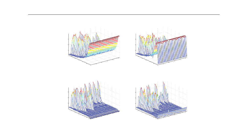
Fig. 2. Structure of software PLL for a single-phase grid-connected power co nverter.
4.1 Proposed synchronization subsystem
The Controller block of the software PLL is commonly implemented as a PI controller or, more
generally, as a first order or second order low pass filter, however, recent researching works on
DWTs for co ntrol applications suggest that the performance of PI controllers can be improved
by using DWTs (Parvez & Gao, 2005). The proposed software PLL substitutes the PI controller
by a DWT implemented using filter banks. The inner structure of the Controller in case of the
proposed software PLL is shown in Fig. 3. As it can be seen, it consists of one Buffer, where
2
L
sampl es of the input are buffered to be analyzed and L is the number of decomposition
levels, the Dyadic Analysis Filter Bank from the Signal Processing Blockset in MatLab/Simulink,
which generates an output vector containing the output at each sub-band. Then, the loop
gains, contained in the Constant Diagonal Matrix Block and needed to adjust the response of
the propose d software PLL, are applied. Finally, the Controller output signal is obtained by
addi ng the current output of the previous stage at each sub-band.
Fig. 3. Controller block in the wavelet PLL (WPLL).
5. Simulation results
In order to analyze the perfor mance of the proposed sy nchronization block diverse simulation
tests have been carried out. After the selection of the most suitable mother wavelet considering
diverse decomposition levels and operation conditions, the proposed synchronization system
is employed in order to control a dc machine by means of a grid connected controlled rectifier.
The applied tests include step amplitude variations of the voltage grid from 23
√
2 V to 230
√
2
V and step frequency variations from 47.5 Hz to 52.5 Hz, in both cases including a 7% 5
th
voltage harmonic. The employed sampling frequency is 6.4 kHz.
10
20
30
40
50
haar
db10
coif3
bior3.1
rbio1.5
rbio4.4
0.005
0.01
0.015
GA
3
(a)
Error
10
20
30
40
50
haar
db10
coif3
bior3.1
rbio1.5
rbio4.4
0.005
0.01
0.015
GA
3
(b)
Error
10
20
30
40
50
haar
db10
coif3
bior3.1
rbio1.5
rbio4.4
0.5
1
1.5
GA
3
(c)
Ripple
10
20
30
40
50
haar
db10
coif3
bior3.1
rbio1.5
rbio4.4
0.5
1
1.5
GA
3
(d)
Ripple
Fig. 4. L=3. a) Magnitude of the WPLL average error after the voltage amplitude step, b)
magnitude of the WPLL ave rage error after the fundamental grid frequency step, c) ripple of
the WPLL error af ter the voltage amplitude step and d) r ipple of the WPLL error after the
voltage amplitude step.
5.1 Selection of the mother wavelet
The selection of the most suitable mother wavelet has been carried out considering
decomposition levels (L) in the range
[3, 6]. At each decomposition level, diverse values of
the WPLL loop gains have been applied under the operation conditions described previously.
The obtained results, the average error magnitude of the WPLL and the ripple of this error,
have been measured 0.5 s after each transi ent in ord er to compare the performance of each
mother wavelet. Figs. 4, 5, 6 and 7 show the obtaine d results for L in
[3, 6].
From Fig. 4, the best results at L
= 3 are obtained by applying a Daubechies 7 mother wavelet
with a loop gain at the lowest frequency sub-band GA
3
= 39. In this case, the cumulative
measured average error o f the WPLL falls to 1.1
·10
−3
V after the first transient, which re aches
5.2
·10
−3
V after the freq uency step. The error ripple measured after the grid voltage transients
are 0.23 V and 0.16 V. The worst results are obtained in case of Daubechies 4 at GA
3
, reaching
cumulative average errors of 2.0
· 10
−2
V after both grid voltage transients. In case of the
measured error ripple, it decreases up to 5.4
·10
−3
V and 4.6 · 10
−2
respectively but, as it will
be shown in the following subsection, the phase of the input signal is not tracked accurately
due to the average error.
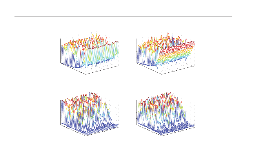
In case of four decomposition levels (L
= 4, in Fig. 5), the most suitable mother wavelet is
Haar applying GA
4
= 43. The obtained cumulative average errors after each transient of the
grid voltage are 1.1
·10
−3
V and 2.0 ·10
−3
respectively. The measured ripples are 0.14 V and
0.16 V respectively. In comparison to the obtained results for L
= 3, in this case (L = 4)
the cumulative error after the grid frequency transient is reduced to 38%. The com parisson
of the measured ripples using L
= 3 and L = 4 shows that, after the first transient, L = 4
with Haar wavelets results on be tter results. The worst results in case of L
= 4 are obtained
221
Discrete Wavelet Transforms for Synchronization
of Power Converters Connected to Electrical Grids
10
20
30
40
50
haar
db10
coif3
bior3.1
rbio1.5
rbio4.4
0.005
0.01
0.015
GA
4
(a)
Error
10
20
30
40
50
haar
db10
coif3
bior3.1
rbio1.5
rbio4.4
0.005
0.01
0.015
GA
4
(b)
Error
10
20
30
40
50
haar
db10
coif3
bior3.1
rbio1.5
rbio4.4
0.5
1
1.5
GA
4
(c)
Ripple
10
20
30
40
50
haar
db10
coif3
bior3.1
rbio1.5
rbio4.4
0.5
1
1.5
GA
4
(d)
Ripple
Fig. 5. L=4. a) Magnitude of the WPLL average error after the voltage amplitude step, b)
magnitude of the WPLL ave rage error after the fundamental grid frequency step, c) ripple of
the WPLL error af ter the voltage amplitude step and d) r ipple of the WPLL error after the
voltage amplitude step.
by employing Coif�et 5 as mother wavelet with GA
4
= 21. The obtained cumulative average
errors are 2.0
·10
−2
V and 8 .6 · 10
−3
V while the measured ripples reach 1.1 ·10
−2
V and 1 .5
V.
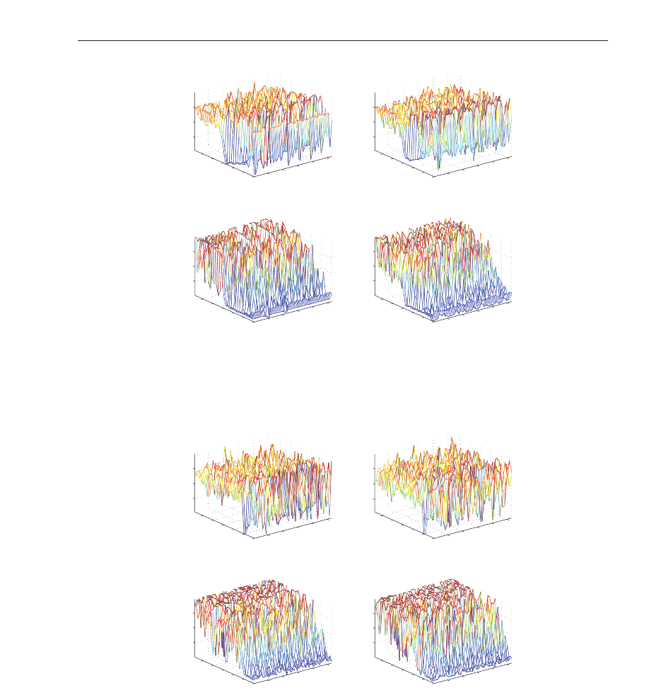
From Fig. 6, again Haar wavelets, in this case with GA
5
= 29, resu lt on the bes t tracking of the
applied g rid voltage. The measured cumulative average errors were 8.1
·10
−4
V and 2.6 ·10
−3
V after the amplitude and frequency steps res pective ly while, in case of the error ripple , the
measured values were 0.14 V and 0.12 V. Com paring these results to the ones obtained in c ase
of L
= 4, the cumulative average er ror decreases after the amplitude step of the grid voltage
due to the added fifth decomposition level. The worst results at L
= 5 are obtained for symlet
8, where the cumulative average errors after the transients are 2
·10
.2
V and 1.7 · 10
−2
V. The
measured error ripples are 2.4
·10
−2
and 0.16 V.
Again i n case of L
= 6 (Fig. 7), Haar wavelets with GA
6
= 22 allow the best tracking
perf ormance to be reached. The measured cumulative average errors in this case were
6.4
·10
−4
V and 9.3 ·10
−4
V cor responding to ampl itude and frequency tr ansients respectively,
which improve s the o b tained results in case of L
= 5. The measured error ripples were 0.16 V
and 0.22 V. The wo rst results were obtained in case of the mother wavelet Biorthonormal 4.4,
with cumulative average errors equal to 2.0
· 10
−2
V and 1.6
−2
V. The error ripple reached
0.02 V and 0.67 V for each grid voltage transient.
The evolutio n of the frequency m easurement o btained by means of the WPLL in case of L
= 3,
Daubechies 7, GA
3
= 39 and GD
3
= 30 is shown in Fig. 8.a where the response time of the
WPLL is 305 ms. Response times with Haar wavelet and four (GA
4
= 43, GD
4
= 18.5) and
five (GA
5
= 29, GD
5
= 4.5 and GD
4
= 3) decomposition levels are shown in Fig. 8.b and 8.c.
In these cases the measured response times are 64 ms and 150 ms corresponding to L
= 4 and
222
Discrete Wavelet Transforms - Theory and Applications
10
20
30
40
50
haar
db10
coif3
bior3.1
rbio1.5
rbio4.4
0.005
0.01
0.015
GA
4
(a)
Error
10
20
30
40
50
haar
db10
coif3
bior3.1
rbio1.5
rbio4.4
0.005
0.01
0.015
GA
4
(b)
Error
10
20
30
40
50
haar
db10
coif3
bior3.1
rbio1.5
rbio4.4
0.5
1
1.5
GA
4
(c)
Ripple
10
20
30
40
50
haar
db10
coif3
bior3.1
rbio1.5
rbio4.4
0.5
1
1.5
GA
4
(d)
Ripple
Fig. 5. L=4. a) Magnitude of the WPLL average error after the voltage amplitude step, b)
magnitude of the WPLL ave rage error after the fundamental grid frequency step, c) ripple of
the WPLL error af ter the voltage amplitude step and d) r ipple of the WPLL error after the
voltage amplitude step.
by employing Coif�et 5 as mother wavelet with GA
4
= 21. The obtained cumulative average
errors are 2.0
·10
−2
V and 8 .6 · 10
−3
V while the measured ripples reach 1.1 ·10
−2
V and 1 .5
V.
From Fig. 6, again Haar wavelets, in this case with GA
5
= 29, resu lt on the bes t tracking of the
applied g rid voltage. The measured cumulative average errors were 8.1
·10
−4
V and 2.6 ·10
−3
V after the amplitude and frequency steps res pective ly while, in case of the error ripple , the
measured values were 0.14 V and 0.12 V. Com paring these results to the ones obtained in c ase
of L
= 4, the cumulative average er ror decreases after the amplitude step of the grid voltage
due to the added fifth decomposition level. The worst results at L
= 5 are obtained for symlet
8, where the cumulative average errors after the transients are 2
·10
.2
V and 1.7 · 10
−2
V. The
measured error ripples are 2.4
·10
−2
and 0.16 V.
Again i n case of L
= 6 (Fig. 7), Haar wavelets with GA
6
= 22 allow the best tracking
perf ormance to be reached. The measured cumulative average errors in this case were
6.4
·10
−4
V and 9.3 ·10
−4
V cor responding to ampl itude and frequency tr ansients respectively,
which improve s the o b tained results in case of L
= 5. The measured error ripples were 0.16 V
and 0.22 V. The wo rst results were obtained in case of the mother wavelet Biorthonormal 4.4,
with cumulative average errors equal to 2.0
· 10
−2
V and 1.6
−2
V. The error ripple reached
0.02 V and 0.67 V for each grid voltage transient.
The evolutio n of the frequency measurement o btained by means of the WPLL in case of L
= 3,
Daubechies 7, GA
3
= 39 and GD
3
= 30 is shown in Fig. 8.a where the response time of the
WPLL is 305 ms. Response times with Haar wavelet and four (GA
4
= 43, GD
4
= 18.5) and
five (GA
5
= 29, GD
5
= 4.5 and GD
4
= 3) decomposition levels are shown in Fig. 8.b and 8.c.
In these cases the measured response times are 64 ms and 150 ms corresponding to L
= 4 and
10
20
30
40
50
haar
db10
coif3
bior3.1
rbio1.5
rbio4.4
0.005
0.01
0.015
GA
5
(a)
Error
10
20
30
40
50
haar
db10
coif3
bior3.1
rbio1.5
rbio4.4
0.005
0.01
0.015
GA
5
(b)
Error
10
20
30
40
50
haar
db10
coif3
bior3.1
rbio1.5
rbio4.4
0.5
1
1.5
GA
5
(c)
Ripple
10
20
30
40
50
haar
db10
coif3
bior3.1
rbio1.5
rbio4.4
0.5
1
1.5
GA
5
(d)
Ripple
Fig. 6. L=5. a) Magnitude of the WPLL average error after the voltage amplitude step, b)
magnitude of the WPLL ave rage error after the fundamental grid frequency step, c) ripple of
the WPLL error af ter the voltage amplitude step and d) r ipple of the WPLL error after the
voltage amplitude step.
10
20
30
40
50
haar
db10
coif3
bior3.1
rbio1.5
rbio4.4
0.005
0.01
0.015
GA
6
(a)
Error
10
20
30
40
50
haar
db10
coif3
bior3.1
rbio1.5
rbio4.4
0.005
0.01
0.015
GA
6
(b)
Error
10
20
30
40
50
haar
db10
coif3
bior3.1
rbio1.5
rbio4.4
0.5
1
1.5
GA
6
(c)
Ripple
10
20
30
40
50
haar
db10
coif3
bior3.1
rbio1.5
rbio4.4
0.5
1
1.5
GA
6
(d)
Ripple
Fig. 7. L=6. a) Magnitude of the WPLL average error after the voltage amplitude step, b)
magnitude of the WPLL ave rage error after the fundamental grid frequency step, c) ripple of
the WPLL error af ter the voltage amplitude step and d) r ipple of the WPLL error after the
voltage amplitude step.
223
Discrete Wavelet Transforms for Synchronization
of Power Converters Connected to Electrical Grids
0 1 2 3
40
45
50
55
60
(a)
Time (s)
Frequency (Hz)
0 1 2 3
−1
−0.5
0
0.5
1
(b)
Time (s)
Error (V)
0 1 2 3
40
45
50
55
60
(c)
Time (s)
Frequency (Hz)
0 1 2 3
−1
−0.5
0
0.5
1
(d)
Time (s)
Error (V)
0 1 2 3
40
45
50
55
60
(e)
Time (s)
Frequency (Hz)
0 1 2 3
−1
−0.5
0
0.5
1
(f)
Time (s)
Error (V)
Fig. 8. Time response of the WPLL. a) Frequency measurement with L = 3, b) WPLL error
with with L
= 3, c) Frequency measurement with L = 4, d) WPLL error with with L = 4, e)
Frequency measurement with L
= 5 and f) WPLL error with with L = 5.
L
= 5. In despite of a higher number of decomposition levels, the response time of Daubechies
7 is the longe st one due to the filter length. Haar wavele ts result on simple filter banks with
low response times. Moreover, from Fig. 8.e, the WPLL performance improves by selecting
more decomposition levels which results on less frequency ripple.
The WPLL outputs, considering Daubechies 7 (L
= 3) and Haar (L = 4 and L = 5), for control
purposes of the grid-connected power converter can be compared by means of Fig. 9, where
1.96 1.98 2 2.02 2.04 2.06 2.08 2.1
−1.5
−1
−0.5
0
0.5
1
1.5
Time (s)
L=3
L=4
L=5
Fig. 9. Time response of the WPLL after the frequency step, at 2 s, from 47.5 Hz to 52.5 Hz.
224
Discrete Wavelet Transforms - Theory and Applications
0 1 2 3
40
45
50
55
60
(a)
Time (s)
Frequency (Hz)
0 1 2 3
−1
−0.5
0
0.5
1
(b)
Time (s)
Error (V)
0 1 2 3
40
45
50
55
60
(c)
Time (s)
Frequency (Hz)
0 1 2 3
−1
−0.5
0
0.5
1
(d)
Time (s)
Error (V)
0 1 2 3
40
45
50
55
60
(e)
Time (s)
Frequency (Hz)
0 1 2 3
−1
−0.5
0
0.5
1
(f)
Time (s)
Error (V)
Fig. 8. Time response of the WPLL. a) Frequency measurement with L = 3, b) WPLL error
with with L
= 3, c) Frequency measurement with L = 4, d) WPLL error with with L = 4, e)
Frequency measurement with L
= 5 and f) WPLL error with with L = 5.
L
= 5. In despite of a higher number of decomposition levels, the response time of Daubechies
7 is the longe st one due to the filter length. Haar wavele ts result on simple filter banks with
low response times. Moreover, from Fig. 8.e, the WPLL performance improves by selecting
more decomposition levels which results on less frequency ripple.
The WPLL outputs, considering Daubechies 7 (L
= 3) and Haar (L = 4 and L = 5), for control
purposes of the grid-connected power converter can be compared by means of Fig. 9, where
1.96 1.98 2 2.02 2.04 2.06 2.08 2.1
−1.5
−1
−0.5
0
0.5
1
1.5
Time (s)
L=3
L=4
L=5
Fig. 9. Time response of the WPLL after the frequency step, at 2 s, from 47.5 Hz to 52.5 Hz.
the time response of the PLL after the frequency transie nt of the grid voltage (at t = 2 s) is
shown.
5.2 Control of a dc motor
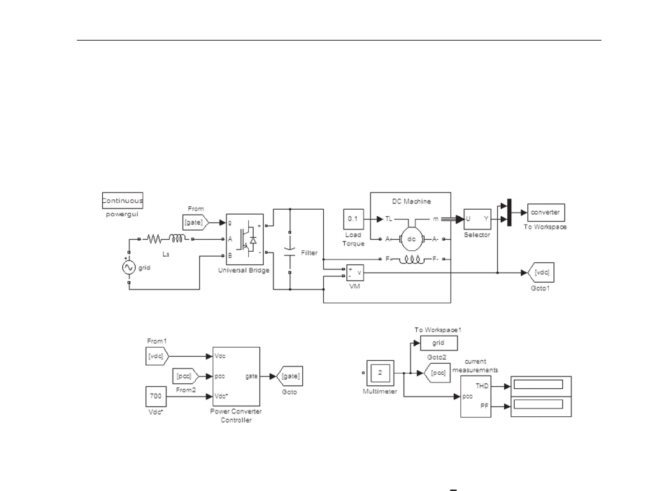
The proposed synchronization subsyste m has been tested in simulati on as a part of the who le
controller in case of a grid-connected power converter feeding a dc motor. The employed
MatLab/Simulink simulation model, including the power stage, the converter controller and
the measurement, is depicted in Fig. 10.
Fig. 10. MatLab/Simulink model of a dc motor controlled by means of a grid-connected
power converter. Top: power stage, including the electrical grid, the power converter and the
dc machine. Bottom: the controller of the power converter and measurement blocks.
The power stage includes a pure sinusoidal waveform with 230
√
2 V amplitude and 50 Hz
frequency as grid voltage. The grid impedance and the inverter side inductance have been
modeled as a series RL with values 0.4 Ω and 2.5 mH. The IGBT+Diode H-bridge is modeled
by means of the Universal Bridge block of the SimPowerSystems Blockset. The dc filtering
stage consist of one 550 μF capacitor and it is connected to the dc motor windings, which
are conne cted in series. The dc machine is modeled as a separately excited dc machine by
means of the DC Machine block. The measured variables in this model are, at the dc motor
side, the motor speed, the output voltage of the power conver ter (across the dc capacitor) and
the output current (flowing through the dc motor), at the e lectrical grid side, the grid voltage
and line current waveforms are al so meas ured.
The inner structure of the employed controller is shown in Fig. 11. The power signals
employed for control purposes (voltage across the dc capacitor, grid voltage and line current)
are filtered out in order to avoid the aliasing due to the sampling process. The PLL block
generates a sinusoidal signal, with unitary amplitude, which is employed to evaluate the
reference current (applied to port iGrid* in current controller). The proportional-integral (PI)
block with K
p
= K
i
= 0.4, employed in case of the SPLL-based model, evaluates the amplitude
of this reference current in order to maintain the dc bus voltage at the reference value, in this
case 450 V. In order to compare the obatined results, the same reference voltage is employ ed
in case of the WPLL-based model, where the Haar wavelet with five decomposition levels, that
225
Discrete Wavelet Transforms for Synchronization
of Power Converters Connected to Electrical Grids
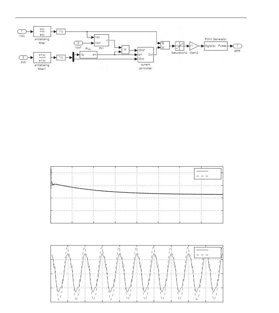
Fig. 11. Structure of the analyzed converter controller.
was analyzed in the previous sections, is applied. The current controller is implemented as a
proportional-resonant controller and, in this case, three resonant blocks have been employed
at frequencies ω
1
= 50 Hz, ω
3
= 150 Hz and ω
3
= 250 Hz. The gains of the controller are
K
p
= 7 and K
1
= K
3
= K
5
= 200. After the control action, in order to obtai n the switching
pattern, the output of the current controller must be divided by the measured dc capacitor
voltage. Then, the g ate pulses of the H-b ridge are generated by the blo ck PWM Generator,
which applies a triangular carrier signal whose frequency matches the sampling frequency,
f
s
= 6.4 kHz.
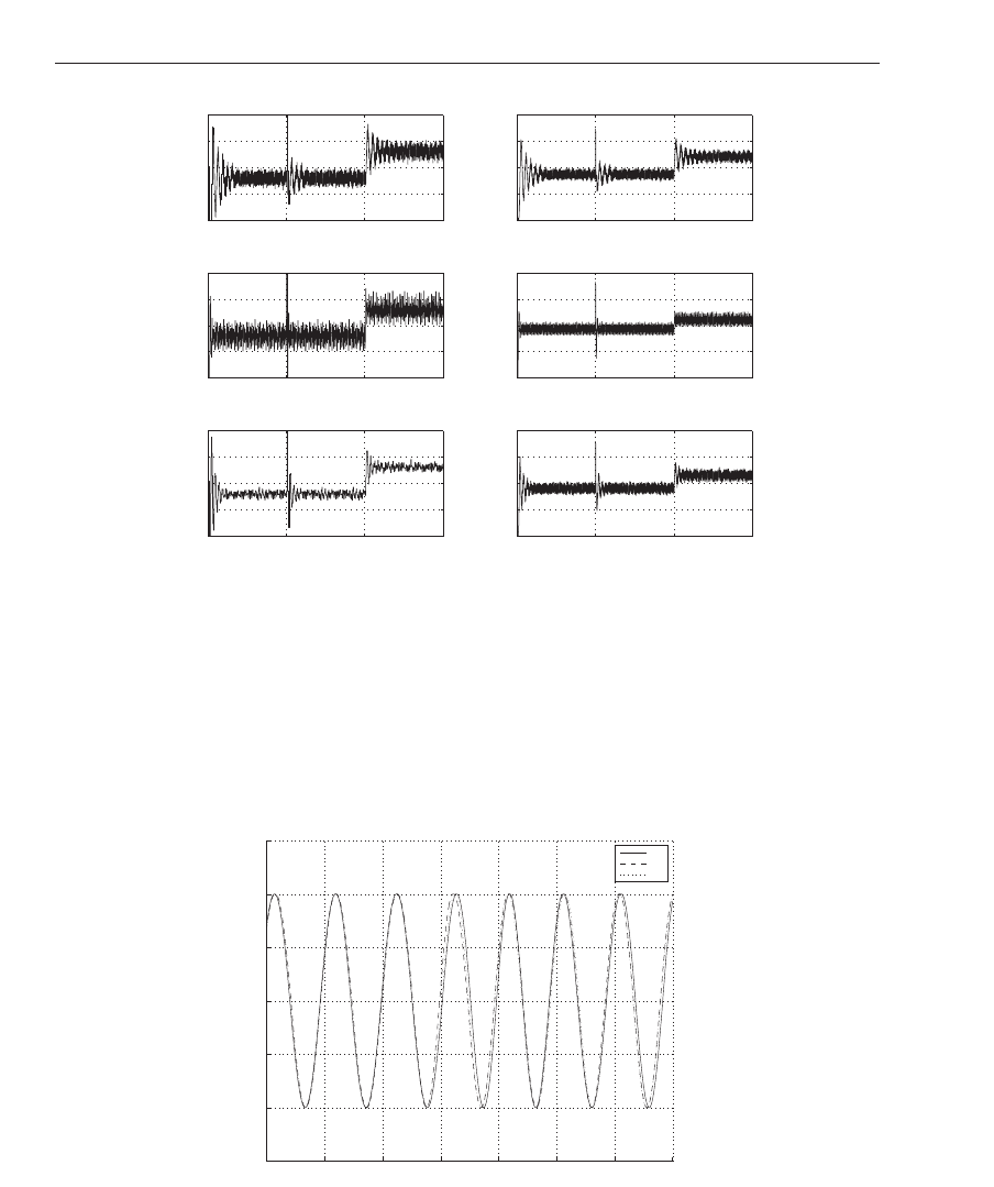
The obtained results corresponding to the dc voltage, in case o f both the conventio nal PLL
and the WPLL, are shown in Fig. 12.a. As it can be seen, the WPLL subsystem results on an
0 0.5 1 1.5 2 2.5 3 3.5 4
0
200
400
600
800
Time (s)
V
dc
(V)
(a)
SPLL
WPLL
9.8 9.82 9.84 9.86 9.88 9.9 9.92 9.94 9.96 9.98 10
−4
−2
0
2
4
Time (s)
i
g
(A)
(b)
SPLL
WPLL
Fig. 12. Structure of the analyzed converter controller.
smoother dc voltage during the moto r starting while the conve ntional SPLL subsystem, based
on a PI controller, results on a 863 V transient, which could damage the power converter
and the motor windings in case of no protection. The re sponse times in both cases, after the
226
Discrete Wavelet Transforms - Theory and Applications

Fig. 11. Structure of the analyzed converter controller.
was analyzed in the previous sections, is applied. The current controller is implemented as a
proportional-resonant controller and, in this case, three resonant blocks have been employed
at frequencies ω
1
= 50 Hz, ω
3
= 150 Hz and ω
3
= 250 Hz. The gains of the controller are
K
p
= 7 and K
1
= K
3
= K
5
= 200. After the control action, in order to obtai n the switching
pattern, the output of the current controller must be divided by the measured dc capacitor
voltage. Then, the g ate puls es of the H-b ridge are generated by the blo ck PWM Generator,
which applies a triangular carrier signal whose frequency matches the sampling frequency,
f
s
= 6.4 kHz.
The obtained results corresponding to the dc voltage, in case o f both the conventio nal PLL
and the WPLL, are shown in Fig. 12.a. As it can be seen, the WPLL subsystem results on an
0 0.5 1 1.5 2 2.5 3 3.5 4
0
200
400
600
800
Time (s)
V
dc
(V)
(a)
SPLL
WPLL
9.8 9.82 9.84 9.86 9.88 9.9 9.92 9.94 9.96 9.98 10
−4
−2
0
2
4
Time (s)
i
g
(A)
(b)
SPLL
WPLL
Fig. 12. Structure of the analyzed converter controller.
smoother dc voltage during the moto r starting while the conve ntional SPLL subsystem, based
on a PI controller, results on a 863 V transient, which could damage the power converter
and the motor windings in case of no protection. The re sponse times in both cases, after the
starti ng transient, are 3.72 s. Thi s is due to the fact that reference current amplitude is obtained,
in both cases, by applying the same PI controller. The current line waveforms, once the dc
motor reaches the steady state in both models (with the conventional SPLL and the WPLL),
are shown in Fig. 12.b. The measured current THDs are 0.67% and 0.55% corresponding to the
conventional SPLL and the proposedl WPLL.
6. Conclusions
This book chapter presents an application of wavelets in grid-connected power converters.
The proposed approach allows wavelet-based software phase locked loops (SPLLs) to be
developed and implemented, replacing the proportional-integral controller in conventional
SPLLs. The proposed app roach results on a more flexible synchronization subsystem who se
characteristics can be adjusted depending o n the electric al grid disturbances. Sim ulation
results, comp aring the performance of the conventional SPLL and the wavelet-based proposed
one, are given in case of a grid-connected power converter feeding a dc motor.
7.References
Bose, B. K. (2006). Power electronics and motor drives : advances and trends, Academic Press.
Bose, B. K. (2009). The past, present, and future of power electronics, IEEE Industrial Electronics
Magazine 3(2): 7–11,14.
Bueno, E. J., Cobreces, S., Rodriguez, F. J., Hernandez, A. & Espinosa, F. (2008). Design of a
back-to- back npc converter interface f or wind turbines with squirrel-cag e inducti on
generator, IEE E Transactions on Energy Conversion 23(3): 932–945.
Bueno , E. J., Hernandez, A., Rodriguez, F. J., Giron, C., Mateos, R. & Cobreces, S. (2009). A
dsp- and fpga-based industrial control with high-speed communication inte rfaces for
grid converters applied to distributed power generation systems, IEEE Transactions
on Industrial Electronics 56(3): 654–669.
Carrasco, J. M., Franquelo, L. G., Bialasiewicz, J. T., Galvan, E., Guisado, R. C. P., Prats, M.
A. M., Leon, J. I. & Moreno-Alfonso, N. (2006). Power-electronic systems for the grid
integration of renewable energy sources: A survey, IEEE Transactions on Industrial
Electronics 53(4): 1002–1016.
Castro, R. M. & Diaz, H. N. (2002). An overview of wavelet transform applicati on in power
systems, 14
th
Power Systems Computation Conference, pp. 6.1–6.9.
Chaari, O., Meunier, M. & Brouaye, F. (1996). Wavelets: a new tool for the res onant
grounded power distribution systems relaying, IEEE Transactions on Power Delivery
11(3): 1301–1308.
Dannehl, J., Fuchs, F. W. & Thφgersen, P. B. (2010). Pi state space current control of
grid-connected pwm converters with lcl filters, IE EE Transactions on Power Electronics
25(9): 2320–2330.
De Mango, F., Liserre, M. & D’Aquila, A. (2006). Overview of anti-islanding algor ithms for pv
systems. part ii: Activemethods, 12th International Power Electronics and Motion Control
Conference, EPE-PEMC 2006, pp. 1884–1889.
De Mango, F., L is erre, M., D’Aquila, A. & Pigazo, A. (2006). Overview of anti-islanding
algorithms for pv systems. part i: Passive m ethods, 12th International Power Electronics
and Motion Control Conference, EPE-PEMC 2006, pp. 1878–1883.
227
Discrete Wavelet Transforms for Synchronization
of Power Converters Connected to Electrical Grids

Dinkhauser, V. & Fuchs, F. W. ( 2008). Roto r turn-to-turn faults of doubly-fed induction
generators in wind energy plants - modelling, simulation and detection, 13th
International P ower E lectronics and Motion Control Conference, pp. 1819–1826.
Driesen, J. & Belmans, R. ( 2002). Active power filter control algorithms using wavelet-based
power definitions, 10th International Conference on Harmonics and Quality of Power,
Vol. 2, pp. 466–471.
El-Am awy, A. A. & Mirbod, A. (1988). An efficient software-controlled pll f or low-frequency
applications, IEEE Transactions on Industrial Electronics 35(2): 341 – 344.
Eren, L. & Devaney, M. J. (2001). Motor bearing damage v ia wavelet analysis of starting
current transient, Proc. of the 18
th
IEEE Instrumentation and Measurement Technology
Conference, Vol . 3, pp. 1797–1800.
Erickson, R. W. & Maksimovic, D. (2001). Fundamentals of power electronics, Kluwer.
Freijedo, F. D., Doval-Gandoy, J., Lopez, O. & Acha, E. (2009). Tuning of phase-locked loops
for power converters under distorted utility conditions, IEEE Transactions on Industry
Applications 45(6): 2039–2047.
Gabe, I. J., Montagner, V. F. & Pinheiro, H. ( 2009). Design and implementation of a robust
current controller for vsi connected to the grid through an lcl filter, IEEE Transactions
on Power Elect ronics 24(6): 1444–1452.
Gandelli, A., Monti, A., Ponci, F. & Santi, E. (2001). Power converter control d esign based on
haar analysis, IEEE 32nd Annual Power Electronics S pecialists Conference, PESC 2001.,
Vol. 3, pp. 1742–1746.
Gandelli, A., Monti, A., Santi, E. & Ponci, F. (2002). Extending haar domain analysis to dc/ac
converters, IEEE Annual Power Electronics Specialists Conference, Vol. 4, pp. 1717–1721.
González, D., Bialasiewicz, J. T., Balcells, J. & Gago, J. (2008). Wavelet-based performance
evaluation of power converters op erating with mo dulated switching fre quency, IEEE
Transactions on Industrial E lectronics 55(8): 3167–3176.
Guerrero, J. M., de Vicuna, L. G., Matas, J., Castilla, M. & Miret, J. (2004). A wireless controller
to enhance dynamic perf ormance of parallel inverters in distributed generation
systems, IEEE Transactions on Power Electronics 19(5): 1205–1213.
Hamid, E. Y. & K awasaki, Z. L. (2001). Wavelet packet transform for rms values and power
measurements, IEEE Power Engineering Review 21(9): 49–51.
Heydt, G. & G alli, A. (1997). Transient power quality problems analyzed using wavelets, IEEE
Transactions on Power Delivery 12(2): 908–915.
Ho, C. N.-M., Cheung, V. S. P. & Chung, H. S.-H. (2009). Constant-frequency hysteresis current
control of grid-connected vsi without bandwidth control, IEEE Transactions on Power
Electronics 24(11): 2484–2495.
Holmes, D. G. & Lipo, T. A. (2003). Pulse Width Modulation for Power Converters: Principles and
Practice, Power, Energy & Industry Applications, 1 edn, Wiley-IEEE Press.
Hsu, C.-F., L ee, T.-T. & Wang, S.-L. (2008). Fpga-based adaptive wavelet neurcontroller design
for dc-dc converter, Proc. of the 7
th
International Conference on Machine Learning and
Cybernetics (ICMLC), Vol. 7, pp. 3833–3838.
Huang, C. & Yang, H. T. (2001). Evolving wavelet-based networ s for short-term load
forecasting, IE E Proceedings - Generation, Transmission and Distribution 148(3): 222–228.
Iwaszkiewicz, A. J. & Perz, B. J. (2007). A novel approach to control of multilevel converter
using wavelets transform, International Conference on Renewable Energies and Power
Quality.
228
Discrete Wavelet Transforms - Theory and Applications