Munson B.R. Fundamentals of Fluid Mechanics
Подождите немного. Документ загружается.

and
(12.49)
Thus, with the assumption that 1i.e., the relative speed of the fluid does not change as it
is deflected by the buckets2, we can combine Eqs. 12.48 and 12.49 to obtain
(12.50)
This change in tangential component of velocity combined with the torque and power equations
developed in Section 12.3 1i.e., Eqs. 12.2 and 12.42gives
where is the mass flowrate through the turbine. Since , it follows that
(12.51)
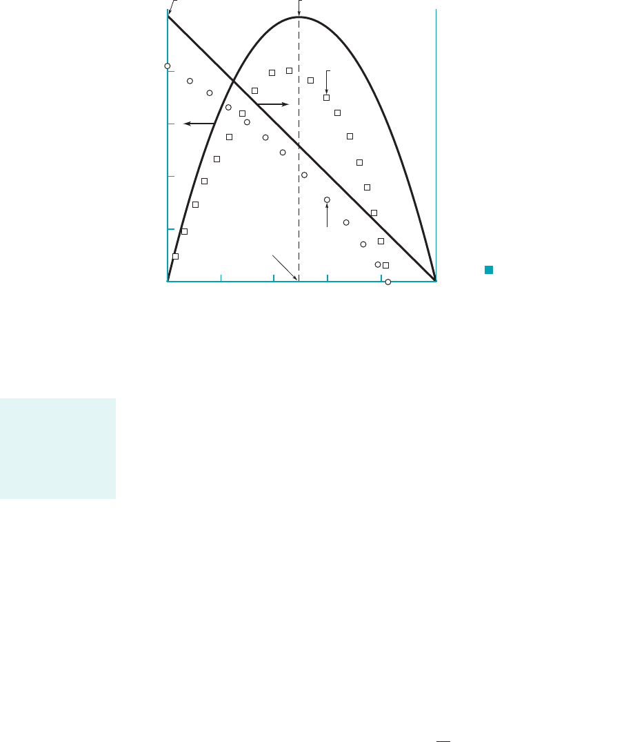
These results are plotted in Fig. 12.28 along with typical experimental results. Note that
1i.e., the jet impacts the bucket2, and 1i.e., the turbine extracts power from the fluid2.
Several interesting points can be noted from the above results. First, the power is a function
of However, a typical value of 1rather than the optimum 2results in a relatively
small 1less than 2%2reduction in power since compared to
Second, although the torque is maximum when the wheel is stopped there is no power
under this condition—to extract power one needs force and motion. On the other hand, the power
output is a maximum when
(12.52)
This can be shown by using Eq. 12.51 and solving for U that gives A bucket speed
of one-half the speed of the fluid coming from the nozzle gives the maximum power. Third, the
maximum speed occurs when 1i.e., the load is completely removed from the turbine, as
would happen if the shaft connecting the turbine to the generator were to break and frictional
torques were negligible2. For this case the turbine is “free wheeling,” and the wa-
ter simply passes across the rotor without putting any force on the buckets.
Although the actual flow through a Pelton wheel is considerably more complex than assumed
in the above simplified analysis, reasonable results and trends are obtained by this simple applica-
tion of the moment-of-momentum principle.
U vR V
1
,
T
shaft
0
dW
#
shaft
dU 0.
U ƒ
max power
V
1
2
1U 02,
1 cos 180° 2.1 cos 165° 1.966,
180°b 165°b.
W
#
shaft
6 0
V
1
7 U
W
#
shaft
T
shaft
v m
#
U1U V
1
211 cos b2
U vR
m
m
#
rQ
T
shaft
m
#
r
m
1U V
1
211 cos b2
V
u2
V
u1
1U V
1
211 cos b2
W
1
W
2
V
u2
W
2
cos b U
12.8 Turbines 677
In Pelton wheel
analyses, we as-
sume the relative
speed of the fluid is
constant (no fric-
tion).
Actual
power
β
T
shaft
Actual
torque
0 0.2 V
1
0.4 V
1
0.6 V
1
0.8 V
1
1.0 V
1
U = r
m
shaft
⋅
–W
–T
shaft
⎥T
shaft
⎥
max
= mr
m
V
1
(1– cos )
⋅
⎥ ⎥
max
= 0.25mV
1
2
(1– cos )
⋅
β
U = 0.5V
1
max power
shaft
⋅
W
shaft
⋅
W
ω
F I G U R E 12.28 Typical
theoretical and experimental power and
torque for a Pelton wheel turbine as a
function of bucket speed.
JWCL068_ch12_645-700.qxd 9/25/08 8:45 PM Page 677
678 Chapter 12 ■ Turbomachines
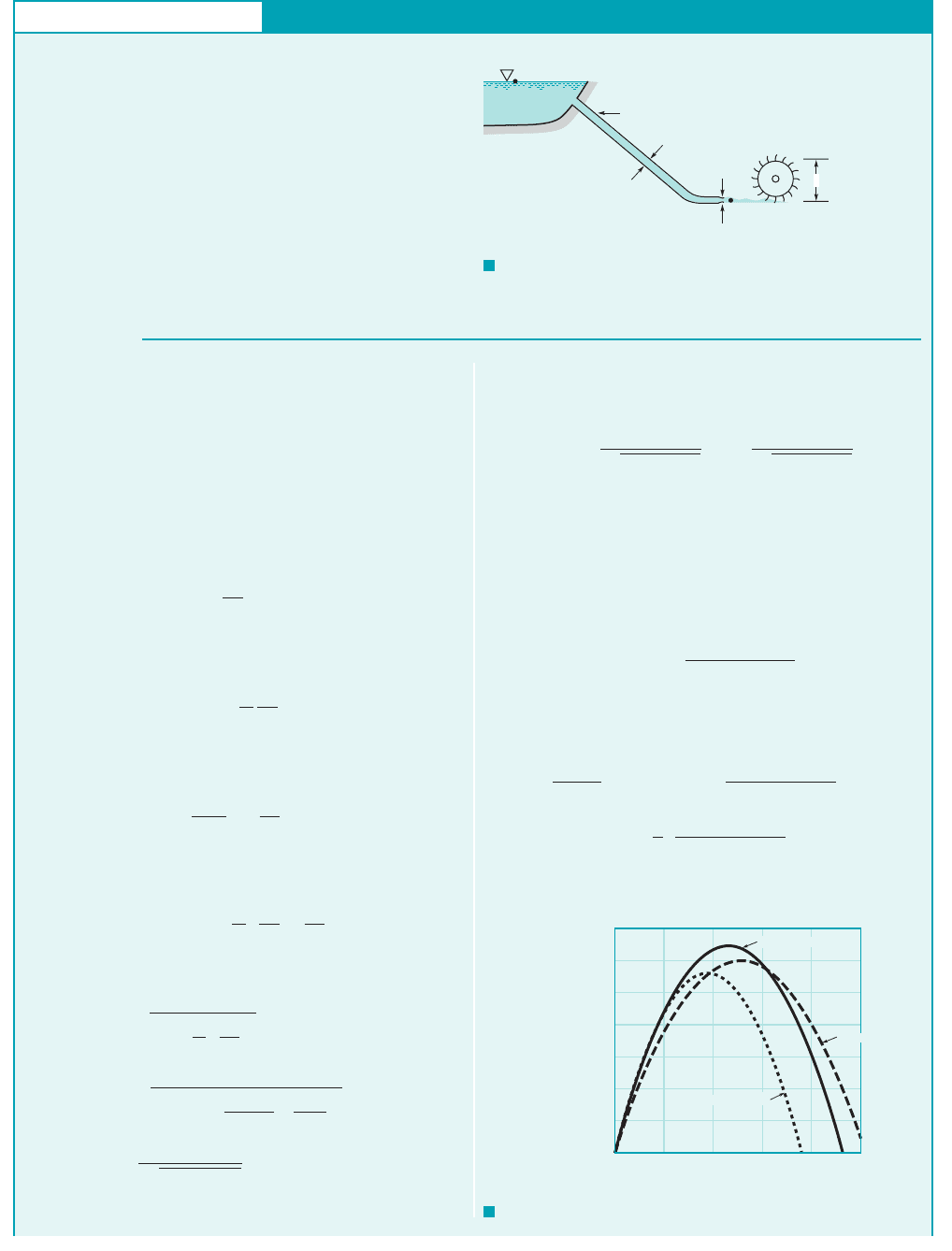
GIVEN Water to drive a Pelton wheel is supplied through a
pipe from a lake as indicated in Fig. E12.6a. The head loss due to
friction in the pipe is important, but minor losses can be
neglected.
FIND (a) Determine the nozzle diameter, D
1
, that will give
the maximum power output.
(b) Determine the maximum power and the angular velocity of
the rotor at the conditions found in part (a).
Pelton Wheel Turbine Characteristics
E
XAMPLE 12.6
S
OLUTION
(a) As indicated by Eq. 12.51, the power output depends on the
flowrate, , and the jet speed at the nozzle exit, V
1
, both of
which depend on the diameter of the nozzle, D
1
, and the head loss
associated with the supply pipe. That is
(1)
The nozzle exit speed, V
1
, can be obtained by applying the
energy equation (Eq. 5.85) between a point on the lake sur-
face (where V
0
p
0
0) and the nozzle outlet (where
z
1
p
1
0) to give
(2)
where the head loss is given in terms of the friction factor, f, as
(see Eq. 8.34)
The speed, V, of the fluid in the pipe of diameter D is obtained
from the continuity equation
We have neglected minor losses associated with the pipe entrance
and the nozzle. With the given data, Eq. 2 becomes
(3)
or
(4)
where D
1
is in feet.
113.5
21 152 D
4
1
C
2132.2 ft/s
2
21200 ft2
1 0.02 a
1000 ft
8/12 ft
b a
D
1
8/12
b
4
§
1/2
V
1
£
2gz
0
1 f
/
D
a
D
1
D
b
4
§
1/2
z
0
c1 f
/
D
a
D
1
D
b
4
d
V
2
1
2g
V
A
1
V
1
A
a
D
1
D
b
2
V
1
h
L
f
/
D
V
2
2g
z
0
V
2
1
2g
h
L
W
shaft
QU1U V
1
211 cos 2
Q m
/
By combining Eqs. 1 and 4 and using Q D
2
1
V
1
/4 we obtain
the power as a function of D
1
and U as
(5)
where U is in feet per second and is in ft lb/s. These re-
sults are plotted as a function of U for various values of D
1
in
Fig. 12.6b.
As shown by Eq. 12.52, the maximum power (in terms of its
variation with U) occurs when U V
1
/2, which, when used with
Eqs. 4 and 5, gives
(6)
The maximum power possible occurs when
which according to Eq. 6 can be found as
a
3
2
b
411522 D
5
1
11 152 D
4
1
2
5/2
d 0
dW
shaft
dD
1
1.04 10
6
c
2 D
1
11 152 D
4
1
2
3/2
dW
shaft
/dD
1
0,
W
shaft
1.04 10
6
D
2
1
11 152 D
4
1
2
3/2
W
shaft
W
shaft
323 UD
2
1
21 152 D
4
1
CU
113.5
21 152 D
4
1
§
z
0
= 200 ft
= 1000 ft, f = 0.02ᐉ
D = 8 in
z
1
= 0
D
1
β
= 150 deg
(0)
2R = 3 ft
(1)
F I G U R E E12.6
a
F I G U R E E12.6
b
D
1
= 0.239 ft
D
1
= 0.200 ft
D
1
= 0.300 ft
U, ft/s
35,000
30,000
25,000
20,000
15,000
10,000
5,000
0 20 40 60 80 100
0
−W
shaft
, ft
•
lb/s
JWCL068_ch12_645-700.qxd 9/25/08 8:46 PM Page 678

In previous chapters we mainly treated turbines 1and pumps2as “black boxes” in the flow that
removed 1or added2energy to the fluid. We treated these devices as objects that removed a certain
shaft work head from or added a certain shaft work head to the fluid. The relationship between the
shaft work head and the power output as described by the moment-of-momentum considerations is
illustrated in Example 12.7.
12.8 Turbines 679
or
Thus, the nozzle diameter for maximum power output is
(Ans)
(b) The corresponding maximum power can be determined
from Eq. 6 as
or
(Ans)
The rotor speed at the maximum power condition can be obtained
from
where V
1
is given by Eq. 4. Thus,
(Ans) ⫽ 295 rpm
⫽ 30.9 rad/s ⫻ 1 rev/2 rad ⫻ 60 s/min
⫽
V
1
2R
⫽
113.5
21 ⫹ 15210.2392
4
ft/s
2a
3
2
ftb
U ⫽ R ⫽
V
1
2
⫽⫺59.0 hp
W
shaft
⫽⫺3.25 ⫻ 10
4
ft ⴢ lb
/
s ⫻
1 hp
550 ftⴢlb
/
s
W
shaft
⫽⫺
1.04 ⫻ 10
6
10.2392
2
31 ⫹ 15210.2392
4
4
3
Ⲑ
2
⫽⫺3.25 ⫻ 10
4
ft ⴢ lb
/
s
D
1
⫽ 0.239 ft
304 D
4
1
⫽ 1
COMMENT The reason that an optimum diameter nozzle
exists can be explained as follows. A larger diameter nozzle will
allow a larger flowrate, but will produce a smaller jet velocity be-
cause of the head loss within the supply side. A smaller diameter
nozzle will reduce the flowrate but will produce a larger jet veloc-
ity. Since the power depends on a product combination of flowrate
and jet velocity (see Eq. 1), there is an optimum-diameter nozzle
that gives the maximum power.
These results can be generalized (i.e., without regard to the
specific parameter values of this problem) by considering Eqs. 1
and 3 and the condition that U ⫽ V
1
/2 to obtain
By setting it can be shown (see Problem 12.67)
that the maximum power occurs when
which gives the same results obtained earlier for the specific pa-
rameters of the example problem. Note that the optimum condi-
tion depends only on the friction factor and the length-to-diameter
ratio of the supply pipe. What happens if the supply pipe is fric-
tionless or of essentially zero length?
D
1
⫽ D
^
a2f
/
D
b
1/4
dW
shaft
/dD
1
⫽ 0,
⫻ 12gz
0
2
3/2
D
2
1
^
a1 ⫹ f
/
D
5
D
4
1
b
3/2
W
shaftU⫽V
1
Ⲑ
2
⫽⫺
p
16
r 11 ⫺ cos b2
GIVEN Water flows through the Pelton wheel turbine shown
in Fig. 12.24. For simplicity we assume that the water is turned
by the blade. 180°
Maximum Power Output for a Pelton Wheel Turbine
E
XAMPLE 12.7
S
OLUTION
(b) the absolute velocity at the exit is zero, or
(c) the exiting stream flows in the direction of the incoming
stream.
According to Eq. 12.52, the maximum power occurs when
which corresponds to the situation shown in Fig.
E12.7b, that is, If viscous effects are negligible,
then and we have which gives
(Ans)
V
2
⫽ 0
U ⫽ W
2
,W
1
⫽ W
2
U ⫽ V
1
Ⲑ
2 ⫽ W
1
.
U ⫽ V
1
Ⲑ
2,
As indicated by Eq. 12.51, the shaft power of the turbine is given by
(1)
For this impulse turbine with the velocity triangles
simplify into the diagram types shown in Fig. E12.7. Three possi-
bilities are indicated:
(a) the exit absolute velocity, is directed back toward the
nozzle,
V
2
,
b ⫽ 180°,
⫽ 2rQ1U
2
⫺ V
1
U2
W
#
shaft
⫽ rQU1U ⫺ V
1
211 ⫺ cos b2
FIND Show, based on the energy equation 1Eq. 5.842, that the
maximum power output occurs when the absolute velocity of the
fluid exiting the turbine is zero.
JWCL068_ch12_645-700.qxd 9/25/08 8:46 PM Page 679
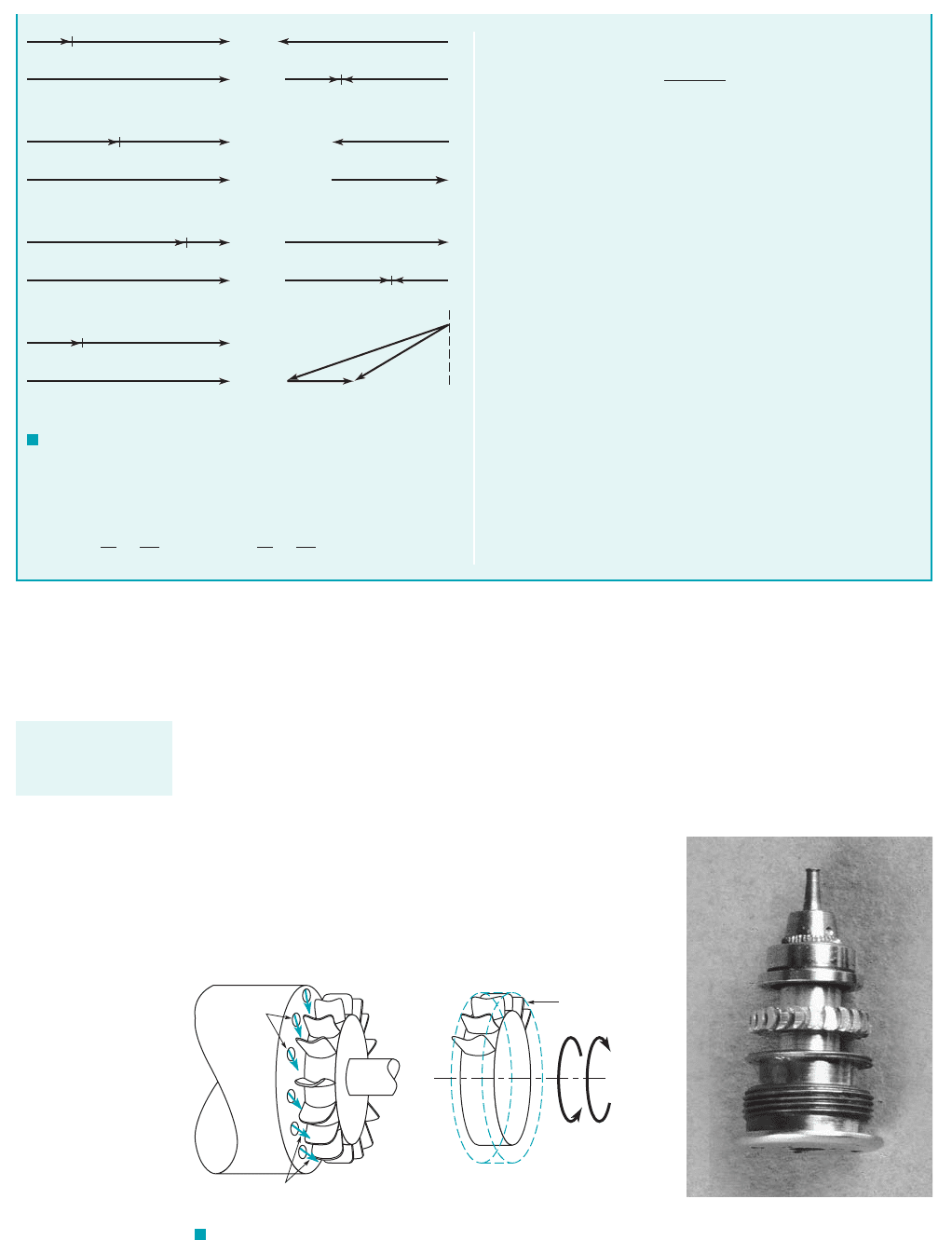
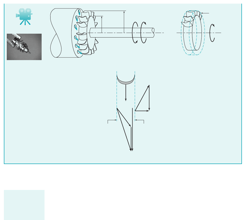
A second type of impulse turbine that is widely used 1most often with air as the working
fluid2is indicated in Fig. 12.29. A circumferential series of fluid jets strikes the rotating blades
which, as with the Pelton wheel, alter both the direction and magnitude of the absolute velocity.
As with the Pelton wheel, the inlet and exit pressures 1i.e., on either side of the rotor2are equal,
and the magnitude of the relative velocity is unchanged as the fluid slides across the blades 1if fric-
tional effects are negligible2.
Typical inlet and exit velocity triangles 1absolute, relative, and blade velocities2are shown in
Fig. 12.30. As discussed in Section 12.2, in order for the absolute velocity of the fluid to be changed
680 Chapter 12 ■ Turbomachines
If we consider the energy equation 1Eq. 5.842for flow across
the rotor we have
p
1
g
V
2
1
2g
z
1
h
S
p
2
g
V
2
2
2g
z
2
h
L
where is the shaft work head. This simplifies to
(2)
since and Note that the impulse turbine obtains
its energy from a reduction in the velocity head. The largest shaft
work head possible 1and therefore the largest power2occurs
when all of the kinetic energy available is extracted by the tur-
bine, giving
(Ans)
This is consistent with the maximum power condition represented
by Fig. E12.7b.
COMMENT As indicated by Eq. 1, if the exit absolute veloc-
ity is not in the plane of the rotor 1i.e., 2, there is a reduc-
tion in the power available 1by a factor of 2. This is also
supported by the energy equation, Eq. 2, as follows. For
the inlet and exit velocity triangles are as shown in Fig. E12.7d.
Regardless of the bucket speed, U, it is not possible to reduce the
value of to zero—there is always a component in the axial di-
rection. Thus, according to Eq. 2, the turbine cannot extract the
entire velocity head; the exiting fluid has some kinetic energy left
in it.
V
2
b 6 180°
1 cos b
b 6 180°
V
2
0
z
1
z
2
.p
1
p
2
h
S
V
2
2
V
2
1
2g
h
L
h
S
UW
1
UW
1
UW
1
UW
1
V
1
V
1
V
1
V
1
Inlet
U
V
2
W
2
= W
1
UV
2
= 0
W
2
= W
1
U
V
2
W
2
= W
1
U
V
2
W
2
= W
1
Outlet
(a)
(b)
(c)
(d)
F I G U R E E12.7
Nozzles
T
shaf
t
Control
volume
ω
Fluid jets
(a)
F I G U R E 12.29 A multinozzle, non-Pelton wheel impulse turbine commonly used with air as the
working fluid.
Dentist drill tur-
bines are usually of
the impulse class.
(b)
JWCL068_ch12_645-700.qxd 9/25/08 8:47 PM Page 680
as indicated during its passage across the blade, the blade must push on the fluid in the direction
opposite of the blade motion. Hence, the fluid pushes on the blade in the direction of the blade’s
motion—the fluid does work on the blade 1a turbine2.
12.8 Turbines 681
Section (1)
V
1
Section (2)
U
U
1
W
1
V
2
U
2
W
2
V
1
θ
F I G U R E 12.30 Inlet and exit velocity
triangles for the impulse turbine shown in Fig. 12.29.
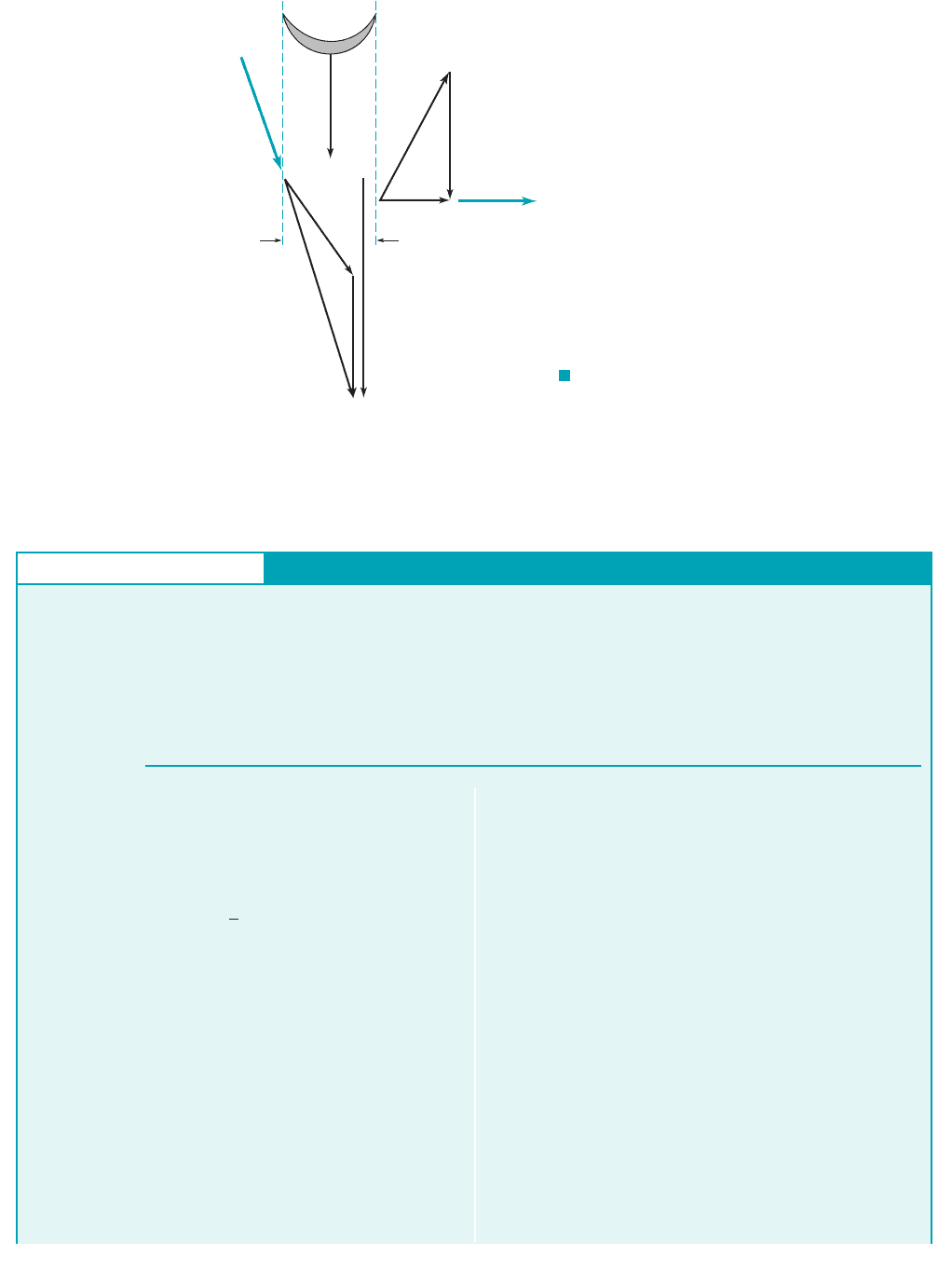
GIVEN An air turbine used to drive the high-speed drill used
by your dentist is shown in Figs. 12.29 and E12.8a. Air exiting
from the upstream nozzle holes forces the turbine blades to move
in the direction shown. The turbine rotor speed is 300,000 rpm,
the tangential component of velocity out of the nozzle is twice the
Non-Pelton Wheel Impulse Turbine (Dental Drill)
E
XAMPLE 12.8
S
OLUTION
We use the fixed, nondeforming control volume that includes the
turbine rotor and the fluid in the rotor blade passages at an in-
stant of time 1see Fig. E12.8b2. The only torque acting on this
control volume is the shaft torque. For simplicity we analyze this
problem using an arithmetic mean radius, where
A sketch of the velocity triangles at the rotor entrance and exit is
shown in Fig. E12.8c.
Application of Eq. 12.5 1a form of the moment-of-momentum
equation2gives
(1)
where is shaft energy per unit of mass flowing through
the turbine. From the problem statement, and
where
(2)
⫽ 394 ft
Ⲑ
s
⫻ 10.168 in. ⫹ 0.133 in.2
Ⲑ
2112 in.
Ⲑ
ft2
U ⫽ vr
m
⫽ 1300,000 rev
Ⲑ
min211 min
Ⲑ
60 s212p rad
Ⲑ
rev2
V
u2
⫽ 0,V
u1
⫽ 2U
w
shaft
w
shaft
⫽⫺U
1
V
u1
⫹ U
2
V
u2
r
m
⫽
1
2
1r
0
⫹ r
i
2
r
m
,
blade speed, and the tangential component of the absolute veloc-
ity out of the rotor is zero.
FIND Estimate the shaft energy per unit mass of air flowing
through the turbine.
is the mean-radius blade velocity. Thus, Eq. 112becomes
(Ans)
COMMENT
For each lbm of air passing through the turbine
there is 9640 of energy available at the shaft to drive the
drill. However, because of fluid friction, the actual amount of en-
ergy given up by each slug of air will be greater than the amount
available at the shaft. How much greater depends on the effi-
ciency of the fluid-mechanical energy transfer between the fluid
and the turbine blades.
Recall that the shaft power, , is given by
Hence, to determine the power we need to know the mass flowrate,
which depends on the size and number of the nozzles. Although
the energy per unit mass is large 1i.e., 9640 2, the
flowrate is small, so the power is not “large.”
ft
#
lb
Ⲑ
lbm
m
#
,
W
#
shaft
⫽ m
#
w
shaft
W
#
shaft
ft
#
lb
⫽⫺9640 ft
#
lb
Ⲑ
lbm
⫽ 1⫺310,000 ft
2
Ⲑ
s
2
2
Ⲑ
132.1741ft
#
lbm2
Ⲑ
1lb
#
s
2
22
⫽⫺310,000 ft
2
Ⲑ
s
2
w
shaft
⫽⫺U
1
V
u1
⫽⫺2U
2
⫽⫺21394 ft
Ⲑ
s2
2
JWCL068_ch12_645-700.qxd 9/25/08 8:47 PM Page 681
12.8.2 Reaction Turbines
As indicated in the previous section, impulse turbines are best suited 1i.e., most efficient2for lower
flowrate and higher head operations. Reaction turbines, on the other hand, are best suited for higher
flowrate and lower head situations such as are often encountered in hydroelectric power plants as-
sociated with a dammed river, for example.
In a reaction turbine the working fluid completely fills the passageways through which it
flows 1unlike an impulse turbine, which contains one or more individual unconfined jets of fluid2.
The angular momentum, pressure, and velocity of the fluid decrease as it flows through the tur-
bine rotor—the turbine rotor extracts energy from the fluid.
As with pumps, turbines are manufactured in a variety of configurations—radial-flow,
mixed-flow, and axial-flow. Typical radial- and mixed-flow hydraulic turbines are called Fran-
cis turbines, named after James B. Francis, an American engineer. At very low heads the most
efficient type of turbine is the axial-flow or propeller turbine. The Kaplan turbine, named af-
ter Victor Kaplan, a German professor, is an efficient axial-flow hydraulic turbine with ad-
justable blades. Cross sections of these different turbine types are shown in Fig. 12.31.
As shown in Fig. 12.31a, flow across the rotor blades of a radial-inflow turbine has a ma-
jor component in the radial direction. Inlet guide vanes 1which may be adjusted to allow opti-
mum performance2direct the water into the rotor with a tangential component of velocity. The
absolute velocity of the water leaving the rotor is essentially without tangential velocity. Hence,
the rotor decreases the angular momentum of the fluid, the fluid exerts a torque on the rotor in
the direction of rotation, and the rotor extracts energy from the fluid. The Euler turbomachine
equation 1Eq. 12.22and the corresponding power equation 1Eq. 12.42are equally valid for this
turbine as they are for the centrifugal pump discussed in Section 12.4.
As shown in Fig. 12.31b, for an axial-flow Kaplan turbine, the fluid flows through the in-
let guide vanes and achieves a tangential velocity in a vortex 1swirl2motion before it reaches the
682 Chapter 12 ■ Turbomachines
V12.4 Dental drill
r
i
= 0.133 in
r
o
= 0.168 in
T
shaft
T
shaf
t
Control
volume
Section (1) Section (2)
U
U
1
V
1
V
1
θ
V
2
W
1
U
2
W
2
(a)
(b)
(c)
ω
■ F I G U R E E12.8
Reaction turbines
are best suited for
higher flowrate and
lower head situa-
tions.
JWCL068_ch12_645-700.qxd 9/25/08 8:47 PM Page 682
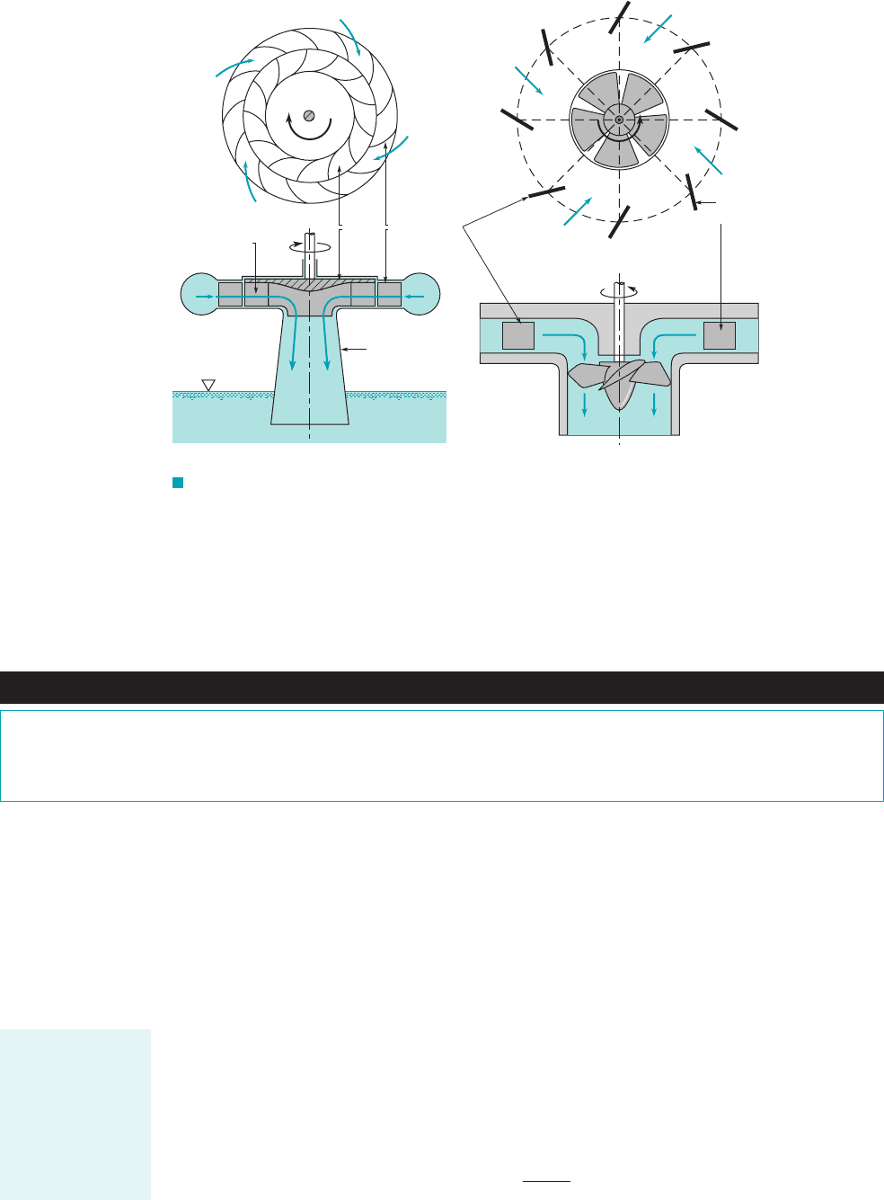
rotor. Flow across the rotor contains a major axial component. Both the inlet guide vanes and the
turbine blades can be adjusted by changing their setting angles to produce the best match 1opti-
mum output2for the specific operating conditions. For example, the operating head available may
change from season to season and/or the flowrate through the rotor may vary.
12.8 Turbines 683
Rotor blades
ω
Rotor
Adjustable
guide vanes
Draft tube
ω
Adjustable
guide vane
Plan view of guide vanes
ω
(a)(b)
ω
F I G U R E 12.31 (a) Typical radial-flow Francis turbine, (b) typical axial-flow
Kaplan turbine.
Fluids in the News
Fish friendly hydraulic turbine Based on data about what actu-
ally kills fish as they pass through hydraulic turbines, Concepts
NREC produced a rotor design that allows a larger flow passage, a
more uniform pressure distribution, lower levels of shear stress,
and other acceptable trade offs between efficiency and fish surviv-
ability. Tests and projections suggest that the fish friendly turbine
design will achieve 90 percent efficiency, with fish survivability
increased from 60% to 98%.
Pumps and turbines are often thought of as the “inverse” of each other. Pumps add energy
to the fluid; turbines remove energy. The propeller on an outboard motor 1a pump2and the pro-
peller on a Kaplan turbine are in some ways geometrically similar, but they perform opposite tasks.
Similar comparisons can be made for centrifugal pumps and Francis turbines. In fact, some large
turbomachines at hydroelectric power plants are designed to be run as turbines during high-power
demand periods 1i.e., during the day2and as pumps to resupply the upstream reservoir from the
downstream reservoir during low-demand times 1i.e., at night2. Thus, a pump type often has its cor-
responding turbine type. However, is it possible to have the “inverse” of a Pelton wheel turbine—
an impulse pump?
As with pumps, incompressible flow turbine performance is often specified in terms of appro-
priate dimensionless parameters. The flow coefficient, the head coefficient,
and the power coefficient, are defined in the same way for
pumps and turbines. On the other hand, turbine efficiency, is the inverse of pump efficiency. That
is, the efficiency is the ratio of the shaft power output to the power available in the flowing fluid, or
h ⫽
W
#
shaft
rgQh
a
h,
C
p
⫽ W
#
shaft
Ⲑ
rv
3
D
5
,C
H
⫽ gh
a
Ⲑ
v
2
D
2
,
C
Q
⫽ Q
Ⲑ
vD
3
,
Actual head avail-
able for a turbine,
h
a
, is always
greater than shaft
work head, h
s
,
because of head
loss, h
L
, in the
turbine.
JWCL068_ch12_645-700.qxd 9/30/08 8:38 AM Page 683
For geometrically similar turbines and for negligible Reynolds number and surface roughness dif-
ference effects, the relationships between the dimensionless parameters are given functionally by
that shown in Eqs. 12.29, 12.30, and 12.31. That is,
where the functions and are dependent on the type of turbine involved. Also, for tur-
bines the efficiency, is related to the other coefficients according to
As indicated above, the design engineer has a variety of turbine types available for any given
application. It is necessary to determine which type of turbine would best fit the job 1i.e., be most ef-
ficient2before detailed design work is attempted. As with pumps, the use of a specific speed para-
meter can help provide this information. For hydraulic turbines, the rotor diameter D is eliminated
between the flow coefficient and the power coefficient to obtain the power specific speed, where
We use the more common, but not dimensionless, definition of specific speed
(12.53)
That is, is calculated with angular velocity, in rpm; shaft power, in brake horsepower;
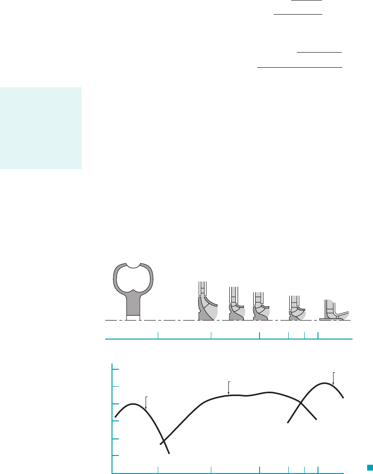
and actual head available, in feet. Optimum turbine efficiency 1for large turbines2as a function
of specific speed is indicated in Fig. 12.32. Also shown are representative rotor and casing cross
sections. Note that impulse turbines are best at low specific speeds; that is, when operating with
large heads and small flowrate. The other extreme is axial-flow turbines, which are the most effi-
cient type if the head is low and if the flowrate is large. For intermediate values of specific speeds,
radial- and mixed-flow turbines offer the best performance.
The data shown in Fig. 12.32 are meant only to provide a guide for turbine-type selection.
The actual turbine efficiency for a given turbine depends very strongly on the detailed design of
the turbine. Considerable analysis, testing, and experience are needed to produce an efficient tur-
bine. However, the data of Fig. 12.32 are representative. Much additional information can be found
in the literature.
h
a
,
W
#
shaft
,v,N¿
sd
N¿
sd
⫽
v1rpm22W
#
shaft
1bhp2
3h
a
1ft24
5
Ⲑ
4
N¿
s
⫽
v2W
#
shaft
Ⲑ
r
1gh
a
2
5
Ⲑ
4
N¿
s
,
h ⫽ C
p
Ⲑ
C
H
C
Q
.h,
f
3
f
1
, f
2
,
C
H
⫽ f
1
1C
Q
2,
C
p
⫽ f
2
1C
Q
2, and
h ⫽ f
3
1C
Q
2
684 Chapter 12 ■ Turbomachines
10 20 40 60 80 100
10 20 40 60 80 100
′
N
sd
100
90
80
70
%
η
Francis
Impulse
Kaplan
Impulse turbines
Radial-flow Mixed-flow Axial-flow
Reaction turbines
′
N
sd
F I G U R E 12.32
Typical turbine cross sections
and maximum efficiencies as a
function of specific speed.
Specific speed may
be used to approxi-
mate what kind of
turbine geometry
(axial to radial)
would operate most
efficiently.
JWCL068_ch12_645-700.qxd 9/25/08 8:48 PM Page 684

12.9 Compressible Flow Turbomachines
12.9 Compressible Flow Turbomachines 685
Fluids in the News
Cavitation damage in hydraulic turbines The occurrence of
cavitation in hydraulic pumps seem to be an obvious possibility
since low suction pressures are expected. Cavitation damage can
also occur in hydraulic turbines even though they do not seem
obviously prone to this kind of problem. Local acceleration of
liquid over blade surfaces can be sufficient to result in local pres-
sures low enough to cause fluid vaporization or cavitation.
Further along the flow path, the fluid can decelerate rapidly
enough with accompanying increase in local pressure to make
cavitation bubbles collapse with enough intensity to cause blade
surface damage in the form of material erosion. Over time, this
erosion can be severe enough to require blade repair or replace-
ment which is very expensive. (See Problem 12.80.)
GIVEN A hydraulic turbine is to operate at an angular veloc-
ity of 6 rev兾s, a flowrate of and a head of 20 ft.10 ft
3
Ⲑ
s,
Use of Specific Speed to Select Turbine Type
E
XAMPLE 12.9
S
OLUTION
As shown by Eq. 12.52, for maximum efficiency of a Pelton
wheel the jet velocity is ideally two times the blade velocity.
Thus, or the wheel diameter, is
To obtain a flowrate of at a velocity of
the jet diameter, must be given by
or
A Pelton wheel with a diameter of supplied with
water through a nozzle of diameter is not a prac-
tical design. Typically 1see Fig. 12.222. By using
multiple jets it would be possible to reduce the jet diameter.
However, even with 8 jets, the jet diameter would be 0.211 ft,
which is still too large 1relative to the wheel diameter2to be
practical. Hence, the above calculations reinforce the results
presented in Fig. 12.32—a Pelton wheel would not be practical
for this application. If the flowrate were considerably smaller,
the specific speed could be reduced to the range where a Pelton
wheel would be the type to use 1rather than a mixed-flow reac-
tion turbine2.
d
1
66 D
d
1
⫽ 0.596 ft
D ⫽ 0.952 ft
d
1
⫽ c
4Q
pV
1
d
1
Ⲑ
2
⫽ c
4110 ft
3
Ⲑ
s2
p135.9 ft
Ⲑ
s2
d
1
Ⲑ
2
⫽ 0.596 ft
Q ⫽
p
4
d
2
1
V
1
d
1
,V
1
⫽ 35.9 ft
Ⲑ
s,
Q ⫽ 10 ft
3
Ⲑ
s
D ⫽
V
1
v
⫽
35.9 ft
Ⲑ
s
16 rev
Ⲑ
s ⫻ 2p rad
Ⲑ
rev2
⫽ 0.952 ft
D ⫽ 2R,V
1
⫽ 2vR,
The most efficient type of turbine to use can be obtained by cal-
culating the specific speed, , and using the information of Fig.
12.32. To use the dimensional form of the specific speed indicated
in Fig. 12.32 we must convert the given data into the appropriate
units. For the rotor speed we get
To estimate the shaft power, we assume all of the available head
is converted into power and multiply this amount by an assumed
efficiency 194%2.
Thus for this turbine,
According to the information of Fig. 12.32,
A mixed-flow Francis turbine would
probably give the highest efficiency and
an assumed efficiency of 0.94 is appropriate.
(Ans)
COMMENT What would happen if we wished to use a Pelton
wheel for this application? Note that with only a 20-ft head, the
maximum jet velocity, obtainable 1neglecting viscous effects2
would be
V
1
⫽ 12 gz ⫽ 22 ⫻ 32.2 ft
Ⲑ
s
2
⫻ 20 ft ⫽ 35.9 ft
Ⲑ
s
V
1
,
N¿
sd
⫽
v2W
#
shaft
1h
a
2
5
Ⲑ
4
⫽
1360 rpm2 221.3 hp
120 ft2
5
Ⲑ
4
⫽ 39.3
W
#
shaft
⫽ 21.3 hp
W
#
shaft
⫽ gQzh ⫽ 162.4 lb
Ⲑ
ft
3
2110 ft
3
Ⲑ
s2c
20 ft10.942
550 ft
#
lb
Ⲑ
s
#
hp
d
v ⫽ 6 rev
Ⲑ
s ⫻ 60 s
Ⲑ
min ⫽ 360 rpm
N¿
sd
FIND What type of turbine should be selected? Explain.
Compressible flow turbomachines are in many ways similar to the incompressible flow pumps and
turbines described in previous portions of this chapter. The main difference is that the density of
the fluid 1a gas or vapor2changes significantly from the inlet to the outlet of the compressible flow
machines. This added feature has interesting consequences, benefits, and complications.
JWCL068_ch12_645-700.qxd 9/25/08 8:48 PM Page 685
Compressors are pumps that add energy to the fluid, causing a significant pressure rise and
a corresponding significant increase in density. Compressible flow turbines, on the other hand, re-
move energy from the fluid, causing a lower pressure and a smaller density at the outlet than at
the inlet. The information provided earlier about basic energy considerations 1Section 12.22and
basic angular momentum considerations 1Section 12.32is directly applicable to these turbomachines
in the ways demonstrated earlier.
As discussed in Chapter 11, compressible flow study requires an understanding of the prin-
ciples of thermodynamics. Similarly, an in-depth analysis of compressible flow turbo-machines
requires use of various thermodynamic concepts. In this section we provide only a brief discus-
sion of some of the general properties of compressors and compressible flow turbines. The inter-
ested reader is encouraged to read some of the excellent references available for further informa-
tion 1e.g., Refs. 1–3, 18–202.
12.9.1 Compressors
Turbocompressors operate with the continuous compression of gas flowing through the device. Since
there is a significant pressure and density increase, there is also a considerable temperature increase.
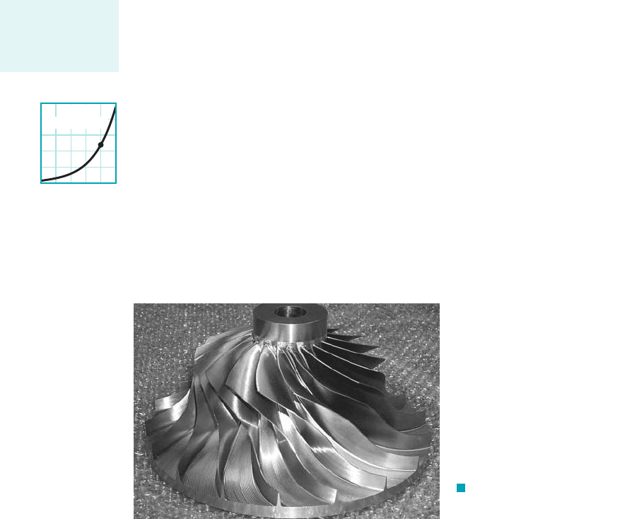
Radial-flow 1or centrifugal2compressors are essentially centrifugal pumps 1see Section 12.42
that use a gas 1rather than a liquid2as the working fluid. They are typically high pressure rise, low
flowrate, and axially compact turbomachines. A photograph of the rotor of a centrifugal compres-
sor rotor is shown in Fig. 12.33.
The amount of compression is typically given in terms of the total pressure ratio,
where the pressures are absolute. Thus, a radial flow compressor with can compress stan-
dard atmospheric air from 14.7 psia to
Higher pressure ratios can be obtained by using multiple stage devices in which flow from the
outlet of the preceding stage proceeds to the inlet of the following stage. If each stage has the same
pressure ratio, PR, the overall pressure ratio after n stages is Thus, as shown by the figure in
the margin, a four-stage compressor with individual stage can compress standard air from
p
0 in
14.7 psia to p
0 out
Adiabatic 1i.e., no heat transfer2compression of a
gas causes an increase in temperature and requires more work than isothermal 1constant temperature2
compression of a gas. An interstage cooler 1i.e., an intercooler heat exchanger2as shown in Fig. 12.34
can be used to reduce the compressed gas temperature and thus the work required.
Relative to centrifugal water pumps, radial compressors of comparable size rotate at much
higher speeds. It is not uncommon for the rotor blade exit speed and the speed of the absolute flow
leaving the impeller to be greater than the speed of sound. That such large speeds are necessary
for compressors can be seen by noting that the large pressure rise designed for is related to the dif-
ferences of several squared speeds 1see Eq. 12.142.
The axial-flow compressor is the other widely used configuration. This type of turboma-
chine has a lower pressure rise per stage, a higher flowrate, and is more radially compact than a
centrifugal compressor. As shown in Fig. 12.35, axial-flow compressors usually consist of several
stages, with each stage containing a rotor/stator row pair. For an 11-stage compressor, a compres-
sion ratio of per stage gives an overall pressure ratio of As the gas 1.2
11
7.4.p
02
p
01
PR 1.2
2
4
14.7 235 psia.
PR 2.0
PR
n
.
3.0 14.7 44.1 psia.
PR 3.0
PR p
02
p
01
,
686 Chapter 12 ■ Turbomachines
F I G U R E 12.33 Centrifugal
compressor rotor. (Photograph courtesy of
concepts NREC.)
Multistaging is
common in high-
pressure ratio
compressors.
543
Stage, n
210
0
100
200
300
400
500
P
0 out,
psia
PR
= 2
P
0 in
= 14.7 psia
JWCL068_ch12_645-700.qxd 9/25/08 8:49 PM Page 686