Munson B.R. Fundamentals of Fluid Mechanics
Подождите немного. Документ загружается.


pumps, the blade angle falls in the range of with a normal range of
and with 1Ref. 102. Blades with are called backward curved, whereas
blades with are called forward curved. Pumps are not usually designed with forward
curved vanes since such pumps tend to suffer unstable flow conditions.
b
2
7 90°
b
2
6 90°15° 6 b
1
6 50°
20° 6 b
2
6 25°,15°35°,b
2
12.4 The Centrifugal Pump 657
GIVEN Water is pumped at the rate of 1400 gpm through a
centrifugal pump operating at a speed of 1750 rpm. The impeller
has a uniform blade height, b, of 2 in. with in. and
in., and the exit blade angle is 1see Fig. 12.82. As-
sume ideal flow conditions and that the tangential velocity com-
ponent, of the water entering the blade is zero 1a
1
90°2.V
u1
,
23°b
2
r
2
7.0
r
1
1.9
Centrifugal Pump Performance Based on Inlet/Outlet
Velocities
E
XAMPLE 12.2
S
OLUTION
(Ans)
(c) From Eq. 12.11, with the power transferred to the
fluid is given by the equation
(Ans)
Note that the ideal head rise and the power transferred to the
fluid are related through the relationship
COMMENT It should be emphasized that results given in
the previous equation involve the ideal head rise. The actual
head-rise performance characteristics of a pump are usually
determined by experimental measurements obtained in a testing
laboratory. The actual head rise is always less than the ideal head
rise for a specific flowrate because of the loss of available energy
associated with actual flows. Also, it is important to note that
even if actual values of U
2
and V
r2
are used in Eq. 12.16, the ideal
head rise is calculated. The only idealization used in this exam-
ple problem is that the exit flow angle is identical to the blade an-
gle at the exit. If the actual exit flow angle was made available in
this example, it could have been used in Eq. 12.16 to calculate
the ideal head rise.
The pump power, is the actual power required to
achieve a blade speed of 107 ft s, a flowrate of 1400 gpm, and the
tangential velocity, V
2
, associated with this example. If pump
losses could somehow be reduced to zero (every pump designer’s
dream), the actual and ideal head rise would have been identical
at 316 ft. As is, the ideal head rise is 316 ft and the actual head rise
something less.
W
#
shaft
,
W
#
shaft
rgQh
i
161,500 ft
#
lb
s211 hp
550 ft
#
lb
s2 112 hp
11.94 slugs
ft
3
211400 gpm21107 ft
s2195.0 ft
s2
311slug
#
ft
s
2
2
lb417.48 gal
ft
3
2160 s
min2
W
#
shaft
rQU
2
V
u2
V
u1
0,
316 ft
1107 ft
s2
2
32.2 ft
s
2
1107 ft
s215.11 ft
s2 cot 23°
32.2 ft
s
2
(a) At the exit the velocity diagram is as shown in Fig. 12.8c,
where is the absolute velocity of the fluid, is the relative
velocity, and is the tip velocity of the impeller with
Since the flowrate is given, it follows that
or
From Fig. 12.8c we see that
so that
(Ans)
(b) From Eq. 12.15 the ideal head rise is given by
(Ans)
Alternatively, from Eq. 12.16, the ideal head rise is
h
i
U
2
2
g
U
2
V
r2
cot b
2
g
316 ft
h
i
U
2
V
u2
g
1107 ft
s2195.0 ft
s2
32.2 ft
s
2
95.0 ft
s
1107 5.11 cot 23°2 ft
s
V
u2
U
2
V
r2
cot b
2
cot b
2
U
2
V
u2
V
r2
5.11 ft
s
1400 gpm
17.48 gal
ft
3
2160 s
min212p217
12 ft212
12 ft2
V
r2
Q
2pr
2
b
2
Q 2pr
2
b
2
V
r2
107 ft
s
U
2
r
2
v 17
12 ft212p rad
rev2
11750 rpm2
160 s
min2
U
2
W
2
V
2
FIND Determine (a) the tangential velocity component, at
the exit, (b) the ideal head rise, and (c) the power, trans-
ferred to the fluid. Discuss the difference between ideal and actual
head rise. Is the power, , ideal or actual? Explain.W
#
shaft
W
#
shaft
,h
i
,
V
u2
,
JWCL068_ch12_645-700.qxd 9/25/08 8:40 PM Page 657
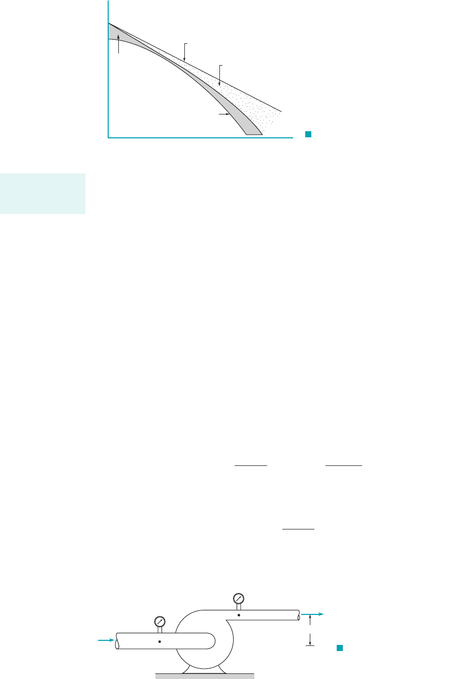
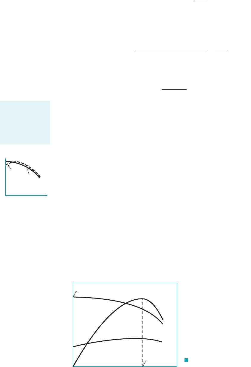
Figure 12.9 shows the ideal head versus flowrate curve 1Eq. 12.182for a centrifugal pump
with backward curved vanes Since there are simplifying assumptions 1i.e., zero losses2
associated with the equation for we would expect that the actual rise in head of fluid, would
be less than the ideal head rise, and this is indeed the case. As shown in Fig. 12.9, the versus
Q curve lies below the ideal head-rise curve and shows a nonlinear variation with Q. The differ-
ences between the two curves 1as represented by the shaded areas between the curves2arise from
several sources. These differences include losses due to fluid skin friction in the blade passages,
which vary as and other losses due to such factors as flow separation, impeller blade-casing
clearance flows, and other three-dimensional flow effects. Near the design flowrate, some of these
other losses are minimized.
Centrifugal pump design is a highly developed field, with much known about pump theory
and design procedures 1see, for example, Refs. 4–62. However, due to the general complexity of
flow through a centrifugal pump, the actual performance of the pump cannot be accurately pre-
dicted on a completely theoretical basis as indicated by the data of Fig. 12.9. Actual pump perfor-
mance is determined experimentally through tests on the pump. From these tests, pump character-
istics are determined and presented as pump performance curves. It is this information that is most
helpful to the engineer responsible for incorporating pumps into a given flow system.
12.4.2 Pump Performance Characteristics
The actual head rise, gained by fluid flowing through a pump can be determined with an ex-
perimental arrangement of the type shown in Fig. 12.10, using the energy equation 1Eq. 5.84 with
where is the shaft work head and is identical to and is the pump head loss2
(12.19)
with sections 112and 122at the pump inlet and exit, respectively. Typically, the differences in ele-
vations and velocities are small so that
(12.20)
The power, gained by the fluid is given by the equation
(12.21)p
f
gQh
a
p
f
,
h
a
⬇
p
2
p
1
g
h
a
p
2
p
1
g
z
2
z
1
V
2
2
V
1
2
2g
h
L
h
i
,h
s
h
a
h
s
h
L
h
a
,
Q
2
,
h
a
h
a
,h
i
,
1b
2
6 90°2.
658 Chapter 12 ■ Turbomachines
F I G U R E 12.9 Effect of losses
on the pump head–flowrate curve.
Flowrate
Head
Other
losses
Actual head, h
a
Theoretical or ideal head, h
i
Friction losses
Ideal and actual
head rise levels dif-
fer by the head loss.
F I G U R E 12.10 Typical
experimental arrangement for determining
the head rise gained by a fluid flowing
through a pump.
(1)
(2)
z
2
–
z
1
JWCL068_ch12_645-700.qxd 9/25/08 8:40 PM Page 658
and this quantity, expressed in terms of horsepower is traditionally called the water horsepower.
Thus,
(12.22)
with expressed in Q in and in ft. Note that if the pumped fluid is not water, the
appearing in Eq. 12.22 must be the specific weight of the fluid moving through the pump.
In addition to the head or power added to the fluid, the overall efficiency, is of interest,
where
The denominator of this relationship represents the total power applied to the shaft of the pump
and is often referred to as brake horsepower 1bhp2. Thus,
(12.23)
The overall pump efficiency is affected by the hydraulic losses in the pump, as previously dis-
cussed, and in addition, by the mechanical losses in the bearings and seals. There may also be
some power loss due to leakage of the fluid between the back surface of the impeller hub plate
and the casing, or through other pump components. This leakage contribution to the overall effi-
ciency is called the volumetric loss. Thus, the overall efficiency arises from three sources, the hy-
draulic efficiency, the mechanical efficiency, and the volumetric efficiency, so that
Performance characteristics for a given pump geometry and operating speed are usually given
in the form of plots of and bhp versus Q 1commonly referred to as capacity2as illustrated in
Fig. 12.11. Actually, only two curves are needed since and bhp are related through Eq. 12.23.
For convenience, all three curves are usually provided. Note that for the pump characterized by
the data of Fig. 12.11, the head curve continuously rises as the flowrate decreases, and in this case
the pump is said to have a rising head curve. As shown by the figure in the margin, pumps may
also have curves that initially rise as Q is decreased from the design value and then fall
with a continued decrease in Q. These pumps have a falling head curve. The head developed by
the pump at zero discharge is called the shutoff head, and it represents the rise in pressure head
across the pump with the discharge valve closed. Since there is no flow with the valve closed, the
related efficiency is zero, and the power supplied by the pump is simply dissipated
as heat. Although centrifugal pumps can be operated for short periods of time with the discharge
valve closed, damage will occur due to overheating and large mechanical stress with any extended
operation with the valve closed.
As can be seen from Fig. 12.11, as the discharge is increased from zero the brake horsepower in-
creases, with a subsequent fall as the maximum discharge is approached. As previously noted, with
and bhp known, the efficiency can be calculated. As shown in Fig. 12.11, the efficiency is a function
h
a
1bhp at Q 02
h
a
Q
h
a
, h,
h
a
, h,
h h
h
h
m
h
v
.
h
v
,h
m
,h
h
,
h
gQh
a
550
bhp
h
power gained by the fluid
shaft power driving the pump
p
f
W
#
shaft
h,
gh
a
ft
3
s,lb
ft
3
,g
p
f
water horsepower
gQh
a
550
12.4 The Centrifugal Pump 659
Pump overall effi-
ciency is the ratio
of power actually
gained by the fluid
to the shaft power
supplied.
F I G U R E 12.11 Typical perfor-
mance characteristics for a centrifugal pump of a
given size operating at a constant impeller speed.
Shutoff head
Head, h
a
Brake horsepower, bhp
Efficiency,
Head
Efficiency
Brake horsepower
0
0
Normal or
design flowrate
Flowrate, Q
η
Falling
head
curve
Rising
head
curve
h
a
Q
JWCL068_ch12_645-700.qxd 9/25/08 8:40 PM Page 659
of the flowrate and reaches a maximum value at some particular value of the flowrate, commonly re-
ferred to as the normal or design flowrate or capacity for the pump. The points on the various curves
corresponding to the maximum efficiency are denoted as the best efficiency points 1BEP2. It is ap-
parent that when selecting a pump for a particular application, it is usually desirable to have the
pump operate near its maximum efficiency. Thus, performance curves of the type shown in Fig.
12.11 are very important to the engineer responsible for the selection of pumps for a particular flow
system. Matching the pump to a particular flow system is discussed in Section 12.4.4.
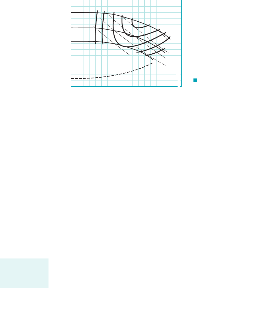
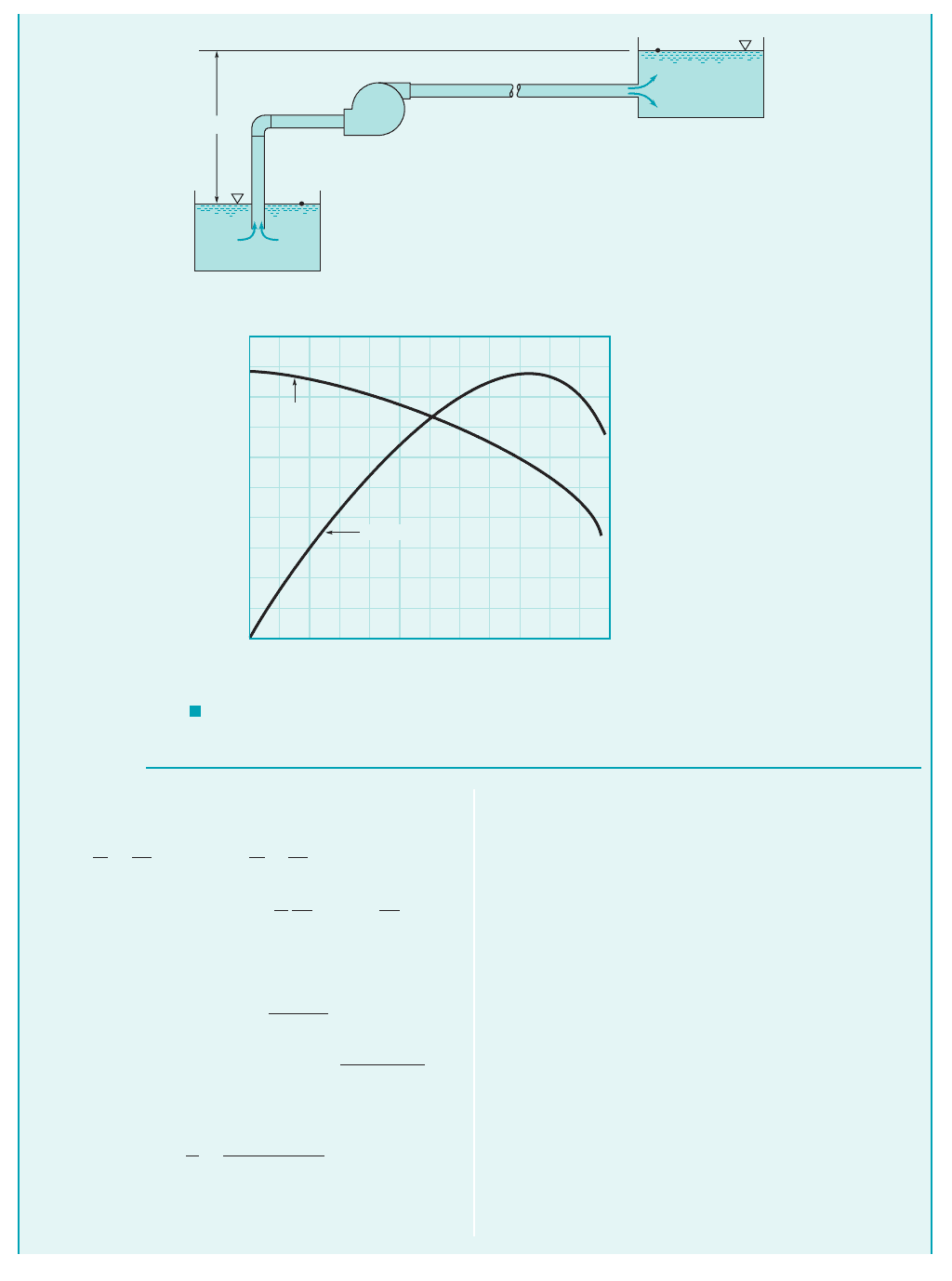
Pump performance characteristics are also presented in charts of the type shown in Fig. 12.12.
Since impellers with different diameters may be used in a given casing, performance characteris-
tics for several impeller diameters can be provided with corresponding lines of constant efficiency
and brake horsepower as illustrated in Fig. 12.12. Thus, the same information can be obtained from
this type of graph as from the curves shown in Fig. 12.11.
It is to be noted that an additional curve is given in Fig. 12.12, labeled which stands
for required net positive suction head. As discussed in the following section, the significance of
this curve is related to conditions on the suction side of the pump, which must also be carefully
considered when selecting and positioning a pump.
12.4.3 Net Positive Suction Head (NPSH)
On the suction side of a pump, low pressures are commonly encountered, with the concomitant
possibility of cavitation occurring within the pump. As discussed in Section 1.8, cavitation occurs
when the liquid pressure at a given location is reduced to the vapor pressure of the liquid. When
this occurs, vapor bubbles form 1the liquid starts to “boil”2; this phenomenon can cause a loss in
efficiency as well as structural damage to the pump. To characterize the potential for cavitation,
the difference between the total head on the suction side, near the pump impeller inlet,
and the liquid vapor pressure head, is used. The position reference for the el-
evation head passes through the centerline of the pump impeller inlet. This difference is called the
net positive suction head 1NPSH2so that
(12.24)
There are actually two values of NPSH of interest. The first is the required NPSH, denoted
that must be maintained, or exceeded, so that cavitation will not occur. Since pressures
lower than those in the suction pipe will develop in the impeller eye, it is usually necessary to de-
termine experimentally, for a given pump, the required This is the curve shown in Fig.
12.12. Pumps are tested to determine the value for as defined by Eq. 12.24, by either
directly detecting cavitation, or by observing a change in the head-flowrate curve 1Ref. 72. The sec-
ond value for NPSH of concern is the available NPSH, denoted which represents the head
that actually occurs for the particular flow system. This value can be determined experimentally,
or calculated if the system parameters are known. For example, a typical flow system is shown in
NPSH
A
,
NPSH
R
,
NPSH
R
.
NPSH
R
,
NPSH
p
s
g
V
s
2
2g
p
v
g
p
v
g,p
s
g V
s
2
2g,
NPSH
R
,
660 Chapter 12 ■ Turbomachines
F I G U R E 12.12 Perfor-
mance curves for a two-stage centrifugal
pump operating at 3500 rpm. Data given for
three different impeller diameters.
0 40 80 120 160 200 240 280 320
NPSH
R
NPSH
R
, ft
8 in. dia
7
6
50%
55
60
63
65
50
55
60
63
65
40 bhp
30
25
20
15
Capacity, gal/min
Head, ft
0
100
200
300
400
500
15
10
5
0
Cavitation, which
may occur when
pumping a liquid, is
usually avoided.
JWCL068_ch12_645-700.qxd 9/25/08 8:40 PM Page 660
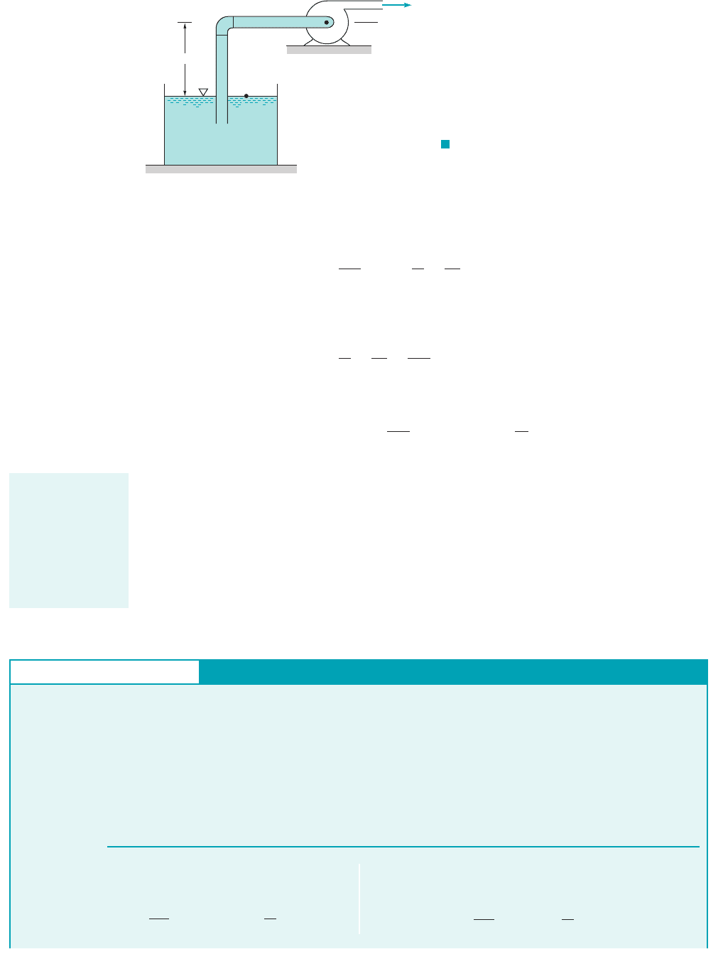
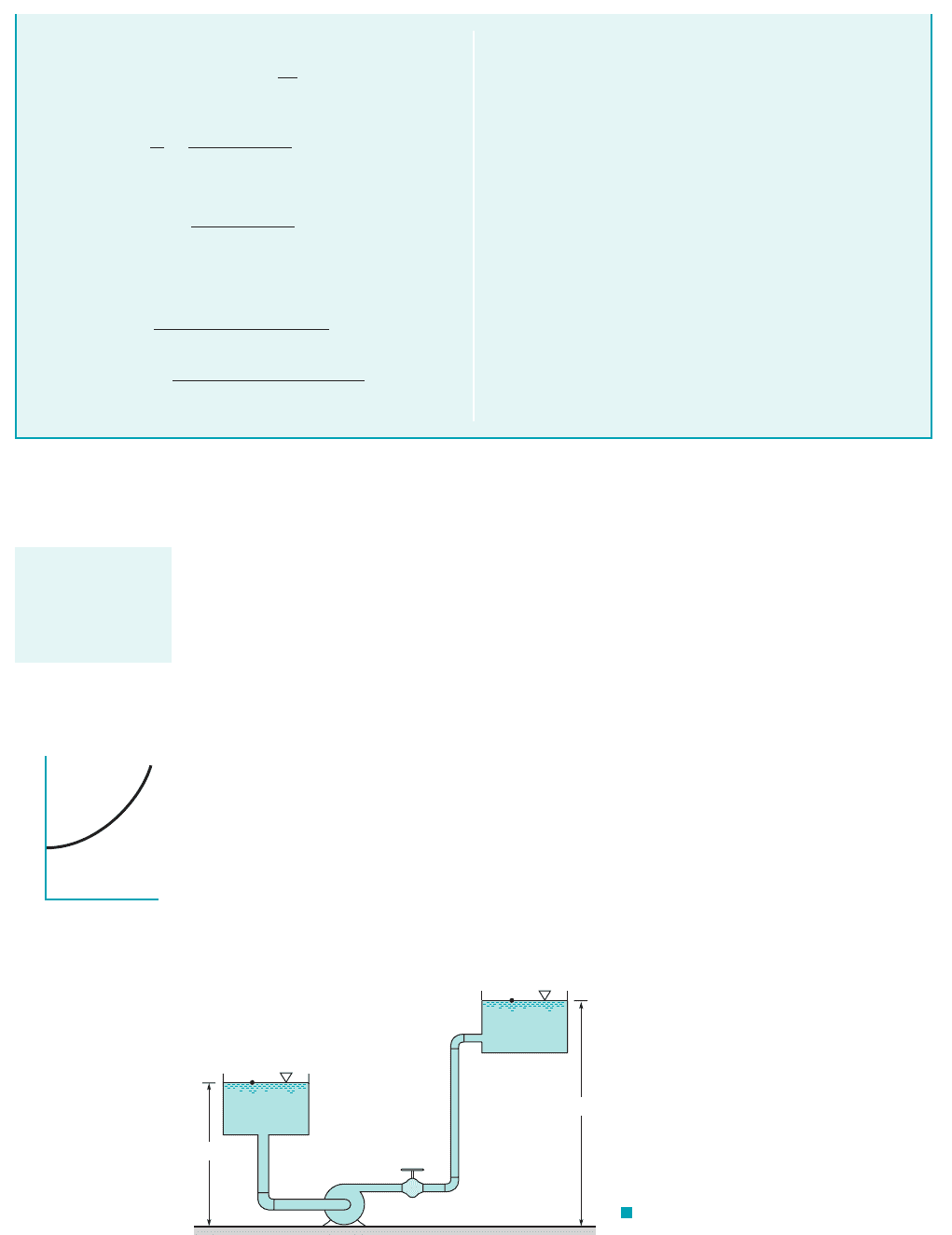
Fig. 12.13. The energy equation applied between the free liquid surface, where the pressure is at-
mospheric, and a point on the suction side of the pump near the impeller inlet yields
where represents head losses between the free surface and the pump impeller inlet. Thus, the
head available at the pump impeller inlet is
so that
(12.25)
For this calculation, absolute pressures are normally used since the vapor pressure is usually spec-
ified as an absolute pressure. For proper pump operation it is necessary that
It is noted from Eq. 12.25 that as the height of the pump impeller above the fluid surface, is
increased, the is decreased. Therefore, there is some critical value for above which the
pump cannot operate without cavitation. The specific value depends on the head losses and the value
of the vapor pressure. It is further noted that if the supply tank or reservoir is above the pump,
will be negative in Eq. 12.25, and the will increase as this height is increased.NPSH
A
z
1
z
1
NPSH
A
z
1
,
NPSH
A
NPSH
R
NPSH
A
p
atm
g
z
1
a
h
L
p
v
g
p
s
g
V
s
2
2g
p
atm
g
z
1
a
h
L
兺h
L
p
atm
g
z
1
p
s
g
V
s
2
2g
a
h
L
p
atm
,
12.4 The Centrifugal Pump 661
F I G U R E 12.13 Schematic of a pump
installation in which the pump must lift fluid from
one level to another.
Reference
plane
p
1
= p
atm
(1)
(2)
z
1
GIVEN A centrifugal pump is to be placed above a large, open
water tank, as shown in Fig. 12.13, and is to pump water at a rate of
At this flowrate the required net positive suction head,
is 15 ft, as specified by the pump manufacturer. The water
temperature is and atmospheric pressure is 14.7 psi. Assume
that the major head loss between the tank and the pump inlet is
due to filter at the pipe inlet having a minor loss coefficient
80 °F
NPSH
R
,
0.5 ft
3
s.
Net Positive Suction Head
E
XAMPLE 12.3
S
OLUTION
From Eq. 12.25 the available net positive suction head, is
given by the equation
NPSH
A
p
atm
g
z
1
a
h
L
p
v
g
NPSH
A
,
Other losses can be neglected. The pipe on the suction
side of the pump has a diameter of 4 in.
FIND Determine the maximum height, that the pump can
be located above the water surface without cavitation. If you were
required to place a valve in the flow path would you place it
upstream or downstream of the pump? Why?
z
1
,
K
L
20.
and the maximum value for will occur when
Thus,
(1)1z
1
2
max
p
atm
g
a
h
L
p
v
g
NPSH
R
NPSH
R
.NPSH
A
z
1
For proper pump
operation, the
available net posi-
tive suction head
must be greater
than the required
net positive suction
head.
JWCL068_ch12_645-700.qxd 9/25/08 8:40 PM Page 661
12.4.4 System Characteristics and Pump Selection
A typical flow system in which a pump is used is shown in Fig. 12.14. The energy equation ap-
plied between points 112and 122indicates that
(12.26)
where is the actual head gained by the fluid from the pump, and represents all friction losses
in the pipe and minor losses for pipe fittings and valves. From our study of pipe flow, we know
that typically varies approximately as the flowrate squared; that is, 1see Section 8.42.
Thus, Eq. 12.26 can be written in the form
(12.27)
where K depends on the pipe sizes and lengths, friction factors, and minor loss coefficients. Equa-
tion 12.27, which is shown in the figure in the margin, is the system equation and shows how the
actual head gained by the fluid from the pump is related to the system parameters. In this case the
parameters include the change in elevation head, and the losses due to friction as expressed
by Each flow system has its own specific system equation. If the flow is laminar, the fric-
tional losses will be proportional to Q rather than 1see Section 8.22.Q
2
KQ
2
.
z
2
z
1
,
h
a
z
2
z
1
KQ
2
h
L
Q
2
h
L
兺h
L
h
a
h
a
z
2
z
1
a
h
L
662 Chapter 12 ■ Turbomachines
Since the only head loss to be considered is the loss
with
it follows that
From Table B.1 the water vapor pressure at is 0.5069 psia
and Equation 112can now be written as
(Ans) 7.65 ft
10.5069 lb
in.
2
21144 in.
2
ft
2
2
62.22 lb
ft
3
15 ft
1z
1
2
max
114.7 lb
in.
2
21144 in.
2
ft
2
2
62.22 lb
ft
3
10.2 ft
g 62.22 lb
ft
3
.
80 °F
a
h
L
120215.73 ft
s2
2
2132.2 ft
s
2
2
10.2 ft
V
Q
A
0.5 ft
3
s
1p
4214
12 ft2
2
5.73 ft
s
a
h
L
K
L
V
2
2g
Thus, to prevent cavitation, with its accompanying poor
pump performance, the pump should not be located higher than
7.65 ft above the water surface.
COMMENT If the valve is placed upstream of the pump, not
only would the pump have to operate with an additional loss in
the system, it would now operate with a lower inlet pressure be-
cause of this additional upstream loss and could now suffer cavi-
tation with its usually negative consequences. If the valve is
placed downstream of the pump, the pump would need to operate
with more loss in the system and with higher back pressure than
without the valve. Depending on the stability of the pump at
higher back pressures, this could be inconsequential or important.
Usually, pumps are stable even with higher back pressures. So,
placing the valve on the downstream side of the pump is normally
the better choice.
(1)
Pump
(2)
z
1
z
2
F I G U R E 12.14
Typical flow system.
h
a
z
2
– z
1
Q
h
a
= z
2
– z
1
+ KQ
2
The system equa-
tion relates the
actual head gained
by the fluid to the
flowrate.
JWCL068_ch12_645-700.qxd 9/25/08 8:41 PM Page 662

There is also a unique relationship between the actual pump head gained by the fluid and
the flowrate, which is governed by the pump design 1as indicated by the pump performance curve2.
To select a pump for a particular application, it is necessary to utilize both the system curve, as
determined by the system equation, and the pump performance curve. If both curves are plotted
on the same graph, as illustrated in Fig. 12.15, their intersection 1point A2represents the operat-
ing point for the system. That is, this point gives the head and flowrate that satisfies both the sys-
tem equation and the pump equation. On the same graph the pump efficiency is shown. Ideally,
we want the operating point to be near the best efficiency point 1BEP2for the pump. For a given
pump, it is clear that as the system equation changes, the operating point will shift. For example,
if the pipe friction increases due to pipe wall fouling, the system curve changes, resulting in the
operating point A shifting to point B in Fig. 12.15 with a reduction in flowrate and efficiency.
The following example shows how the system and pump characteristics can be used to decide if
a particular pump is suitable for a given application.
12.4 The Centrifugal Pump 663
The intersection of
the pump perfor-
mance curve and
the system curve is
the operating point.
Change in
system equation
System
curve
Efficiency
curve
Operating
point
Pump performance
curve
Actual pump
head, h
a
Efficiency
(A)(B)
Flowrate, Q
Elevation (static) head
= z
2
– z
1
F I G U R E 12.15 Utilization of
the system curve and the pump performance
curve to obtain the operating point for the
system.
Fluids in the News
Space Shuttle fuel pumps The fuel pump of your car engine is
vital to its operation. Similarly, the fuels (liquid hydrogen and
oxygen) of each Space Shuttle main engine (there are three per
shuttle) rely on multistage turbopumps to get from storage
tanks to main combustors. High pressures are utilized through-
out the pumps to avoid cavitation. The pumps, some centrifugal
and some axial, are driven by axial-flow, multistage turbines.
Pump speeds are as high as 35,360 rpm. The liquid oxygen is
pumped from 100 to 7420 psia, the liquid hydrogen from 30 to
6515 psia. Liquid hydrogen and oxygen flowrates of about
17,200 gpm and 6100 gpm, respectively, are achieved. These
pumps could empty your home swimming pool in seconds. The
hydrogen goes from 423 °F in storage to 6000 °F in the
combustion chamber!
GIVEN Water is to be pumped from one large, open tank to a
second large, open tank as shown in Fig. E12.4a. The pipe
diameter throughout is 6 in. and the total length of the pipe
between the pipe entrance and exit is 200 ft. Minor loss coeffi-
cients for the entrance, exit, and the elbow are shown, and the
friction factor for the pipe can be assumed constant and equal to
Use of Pump Performance Curves
E
XAMPLE 12.4
0.02. A certain centrifugal pump having the performance charac-
teristics shown in Fig. E12.4b is suggested as a good pump for
this flow system.
FIND With this pump, what would be the flowrate between the
tanks? Do you think this pump would be a good choice?
JWCL068_ch12_645-700.qxd 9/25/08 8:41 PM Page 663
664 Chapter 12 ■ Turbomachines
S
OLUTION
Application of the energy equation between the two free surfaces,
points (1) and (2) as indicated, gives
(1)
Thus, with p
1
p
2
0, V
1
V
2
0, z z
2
z
1
10 ft,
f 0.02, D 6/12 ft, and ᐍ 200 ft, Eq. 1 becomes
(2)
where the given minor loss coefficients have been used. Since
Eq. 2 can be expressed as
(3)h
a
10 4.43 Q
2
V
Q
A
Q1ft
3
/s2
1/4216/12 ft2
2
10.5 1.5 1.02d
V
2
2132.2 ft/s
2
2
h
a
10 c0.02
1200 ft2
16
12 ft2
f
/
D
V
2
2g
a
K
L
V
2
2g
p
1
g
V
2
1
2g
z
1
h
a
p
2
g
V
2
2
2g
z
2
where Q is in ft
3
/s, or with Q in gallons per minute
(4)
Equation 3 or 4 represents the system equation for this particular
flow system and reveals how much actual head the fluid will need
to gain from the pump to maintain a certain flowrate. Perfor-
mance data shown in Fig. E12.4b indicate the actual head the
fluid will gain from this particular pump when it operates at a cer-
tain flowrate. Thus, when Eq. 4 is plotted on the same graph with
performance data, the intersection of the two curves represents
the operating point for the pump and the system. This combina-
tion is shown in Fig. E12.4c with the intersection (as obtained
graphically) occurring at
(Ans)
with the corresponding actual head gained equal to 66.5 ft.
Another concern is whether the pump is operating efficiently
at the operating point. As can be seen from Fig. E12.4c, al-
though this is not peak efficiency, which is about 86%, it is close
(about 84%). Thus, this pump would be a satisfactory choice,
assuming the 1600 gal/min flowrate is at or near the desired
flowrate.
Q 1600 gal/min
h
a
10 2.20 10
5
Q
2
K
L
= 0.5
(1)
K
L
= 1.5
Pump
K
L
= 1.0
(2)
Water
Diameter of pipe = 6 in.
Total pipe length = 200 ft
0 400 800 1200 1600 2000 2400
0
20
40
60
80
100
Flowrate, gal/min
Head, ft
Efficiency, %
Head
Δz = 10 ft
Efficiency
(
b)
(
a)
F I G U R E E12.4
a, b
JWCL068_ch12_645-700.qxd 9/25/08 8:41 PM Page 664
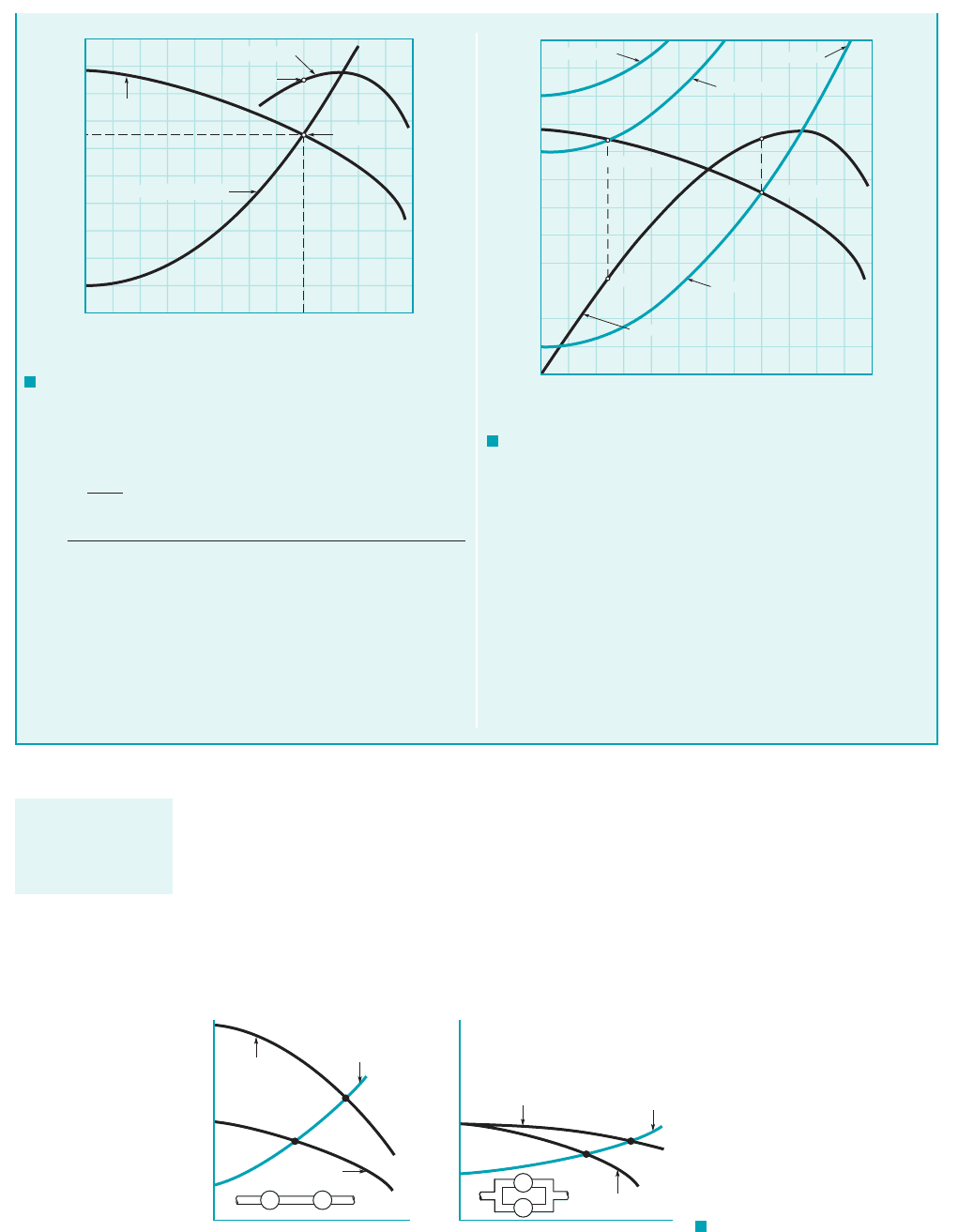
Pumps can be arranged in series or in parallel to provide for additional head or flow capac-
ity. When two pumps are placed in series, the resulting pump performance curve is obtained by
adding heads at the same flowrate. As illustrated in Fig. 12.16a, for two identical pumps in series,
both the actual head gained by the fluid and the flowrate are increased, but neither will be doubled
if the system curve remains the same. The operating point is at 1A2for one pump and moves to 1B2
for two pumps in series. For two identical pumps in parallel, the combined performance curve is
obtained by adding flowrates at the same head, as shown in Fig. 12.16b. As illustrated, the flowrate
for the system will not be doubled with the addition of two pumps in parallel 1if the same system
12.4 The Centrifugal Pump 665
The amount of pump head needed at the pump shaft is
66.5 ft/0.84 79.2 ft. The power needed to drive the pump is
COMMENT By repeating the calculations for z z
2
z
1
80 ft and 100 ft (rather than the given 10 ft), the results
shown in Fig. E12.4d are obtained. Although the given pump
could be used with (provided that the 500 gal/min
flowrate produced is acceptable), it would not be an ideal pump
for this application since its efficiency would be only 36 percent.
¢z 80 ft
17,600 ftⴢlb/s 32.0 hp
162.4 lb
ft
3
2311600 gal
min2
17.48 gal
ft
3
2160 s
min24166.5 ft2
0.84
W
shaft
␥Qh
a
Energy could be saved by using a different pump with a perfor-
mance curve that more nearly matches the new system require-
ments (i.e., higher efficiency at the operating condition). On the
other hand, the given pump would not work at all for
since its maximum head (h
a
88 ft when Q 0) is not enough to
lift the water 100 ft, let alone overcome head losses. This is shown
in Fig. E12.4d by the fact that for the system curve
and the pump performance curve do not intersect.
Note that head loss within the pump itself was accounted for
with the pump efficiency, . Thus, h
s
h
a
, where h
s
is the pump
shaft work head and h
a
is the actual head rise experienced by the
flowing fluid.
h
h
¢z 100 ft
¢z 100 ft
0 1600 2400
0
66.5
100
Flowrate, gal/min
Head, ft
Efficiency, %
Head
Efficiency
84%
Operating
point
System curve (Eq. 4)
Flowrate, gal/min
120
100
80
60
40
20
0
0 400 800 1200 1600 2000 2400
Δz = 80 ft
Δz = 10 ft
1600 gal/min
System
Efficiency
500 gal/min
84%
36%
Head, ft
Efficiency, %
Δz = 100 ft
F I G U R E E12.4
c
(
Continued
)
F I G U R E E12.4
d
For two pumps in
series, add heads;
for two in parallel,
add flowrates.
Two pumps
(B)
(A)
Head, h
a
Head, h
a
Flowrate, Q Flowrate, Q
Two pumps
One pump
One pump
P
P
PP
(A)
(B)
System
curve
System
curve
(a)(b)
F I G U R E 12.16
Effect of operating pumps in
(a) series and (b) in parallel.
JWCL068_ch12_645-700.qxd 9/25/08 8:42 PM Page 665

curve applies2. However, for a relatively flat system curve, as shown in Fig. 12.16b, a significant in-
crease in flowrate can be obtained as the operating point moves from point 1A2to point 1B2.
666 Chapter 12 ■ Turbomachines
As discussed in Chapter 7, dimensional analysis is particularly useful in the planning and execu-
tion of experiments. Since the characteristics of pumps are usually determined experimentally, it
is expected that dimensional analysis and similitude considerations will prove to be useful in the
study and documentation of these characteristics.
From the previous section we know that the principal, dependent pump variables are the ac-
tual head rise, shaft power, and efficiency, We expect that these variables will depend
on the geometrical configuration, which can be represented by some characteristic diameter, D, other
pertinent lengths, and surface roughness, In addition, the other important variables are flowrate,
Q, the pump shaft rotational speed, fluid viscosity, and fluid density, We will only consider
incompressible fluids presently, so compressibility effects need not concern us yet. Thus, any one
of the dependent variables and can be expressed as
and a straightforward application of dimensional analysis leads to
(12.28)
The dependent pi term involving the head is usually expressed as where
is the actual head rise in terms of energy per unit mass, rather than simply which is en-
ergy per unit weight. This dimensionless parameter is called the head rise coefficient. The de-
pendent pi term involving the shaft power is expressed as and this standard
dimensionless parameter is termed the power coefficient. The power appearing in this dimension-
less parameter is commonly based on the shaft 1brake2horsepower, bhp, so that in BG units,
The rotational speed, which appears in these dimensionless groups is ex-
pressed in rad兾s. The final dependent pi term is the efficiency, which is already dimensionless.
Thus, in terms of dimensionless parameters the performance characteristics are expressed as
The last pi term in each of the above equations is a form of Reynolds number that represents
the relative influence of viscous effects. When the pump flow involves high Reynolds numbers, as
is usually the case, experience has shown that the effect of the Reynolds number can be neglected.
For simplicity, the relative roughness, can also be neglected in pumps since the highly irreg-
ular shape of the pump chamber is usually the dominant geometric factor rather than the surface
roughness. Thus, with these simplifications and for geometrically similar pumps 1all pertinent di-
mensions, scaled by a common length scale2, the dependent pi terms are functions of only
so that
(12.29)
(12.30)
(12.31)
h ⫽ f
3
a
Q
vD
3
b
W
#
shaft
rv
3
D
5
⫽ f
2
a
Q
vD
3
b
gh
a
v
2
D
2
⫽ f
1
a
Q
vD
3
b
Q
Ⲑ
vD
3
,
/
i
,
e
Ⲑ
D,
h ⫽
rgQh
a
W
#
shaft
⫽ f
3
a
/
i
D
,
e
D
,
Q
vD
3
,
rvD
2
m
b
C
p
⫽
W
#
shaft
rv
3
D
5
⫽ f
2
a
/
i
D
,
e
D
,
Q
vD
3
,
rvD
2
m
b
C
H
⫽
gh
a
v
2
D
2
⫽ f
1
a
/
i
D
,
e
D
,
Q
vD
3
,
rvD
2
m
b
h,
v,W
#
shaft
⫽ 550 ⫻ 1bhp2.
C
p
⫽ W
#
shaft
Ⲑ
rv
3
D
5
,
h
a
,gh
a
C
H
⫽ gh
a
Ⲑ
v
2
D
2
,
dependent pi term ⫽ fa
/
i
D
,
e
D
,
Q
vD
3
,
rvD
2
m
b
dependent variable ⫽ f1D, /
i
, e, Q, v, m, r2
hh
a
, W
#
shaft
,
r.m,v,
e./
i
,
h.W
#
shaft
,h
a
,
12.5 Dimensionless Parameters and Similarity Laws
Dimensionless pi
terms and similarity
laws are important
pump considera-
tions.
JWCL068_ch12_645-700.qxd 9/25/08 8:42 PM Page 666