Munson B.R. Fundamentals of Fluid Mechanics
Подождите немного. Документ загружается.

Others, such as a windmill or a window fan, are unducted. Some turbomachines include stationary
blades or vanes in addition to rotor blades. These stationary vanes can be arranged to accelerate the
flow and thus serve as nozzles. Or, these vanes can be set to diffuse the flow and act as diffusers.
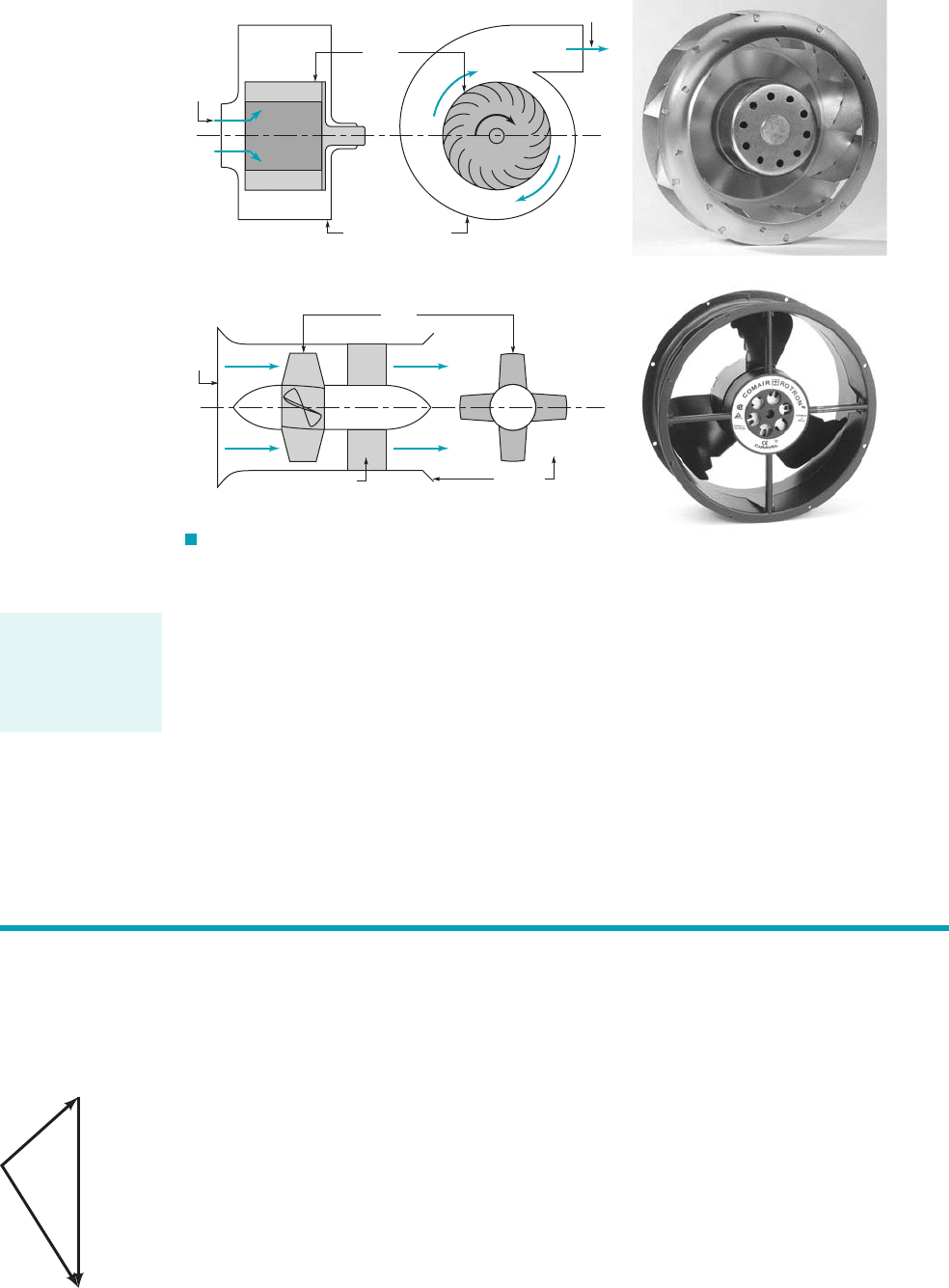
Turbomachines are classified as axial-flow, mixed-flow, or radial-flow machines depending
on the predominant direction of the fluid motion relative to the rotor’s axis as the fluid passes the
blades 1see Fig. 12.22. For an axial-flow machine the fluid maintains a significant axial-flow direc-
tion component from the inlet to outlet of the rotor. For a radial-flow machine the flow across the
blades involves a substantial radial-flow component at the rotor inlet, exit, or both. In other machines,
designated as mixed-flow machines, there may be significant radial- and axial-flow velocity compo-
nents for the flow through the rotor row. Each type of machine has advantages and disadvantages
for different applications and in terms of fluid-mechanical performance.
12.2 Basic Energy Considerations 647
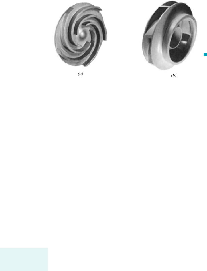
F I G U R E 12.2 (a) A radial-flow turbomachine, (b) an axial-flow turbomachine.
(Photographs courtesy of Comair Rotron, Inc.)
Rotor
Inlet
Housing or casing
Outlet
(
a)
Radial-flow fan
(
b)
Axial-flow fan
Housing
or casing
Inlet
Rotor
Outlet
Stator
or strut
ω
12.2 Basic Energy Considerations
An understanding of the work transfer in turbomachines can be obtained by considering the
basic operation of a household fan 1pump2and a windmill 1turbine2. Although the actual flows
in such devices are very complex 1i.e., three-dimensional and unsteady2, the essential phenom-
ena can be illustrated by use of simplified flow considerations and velocity triangles.
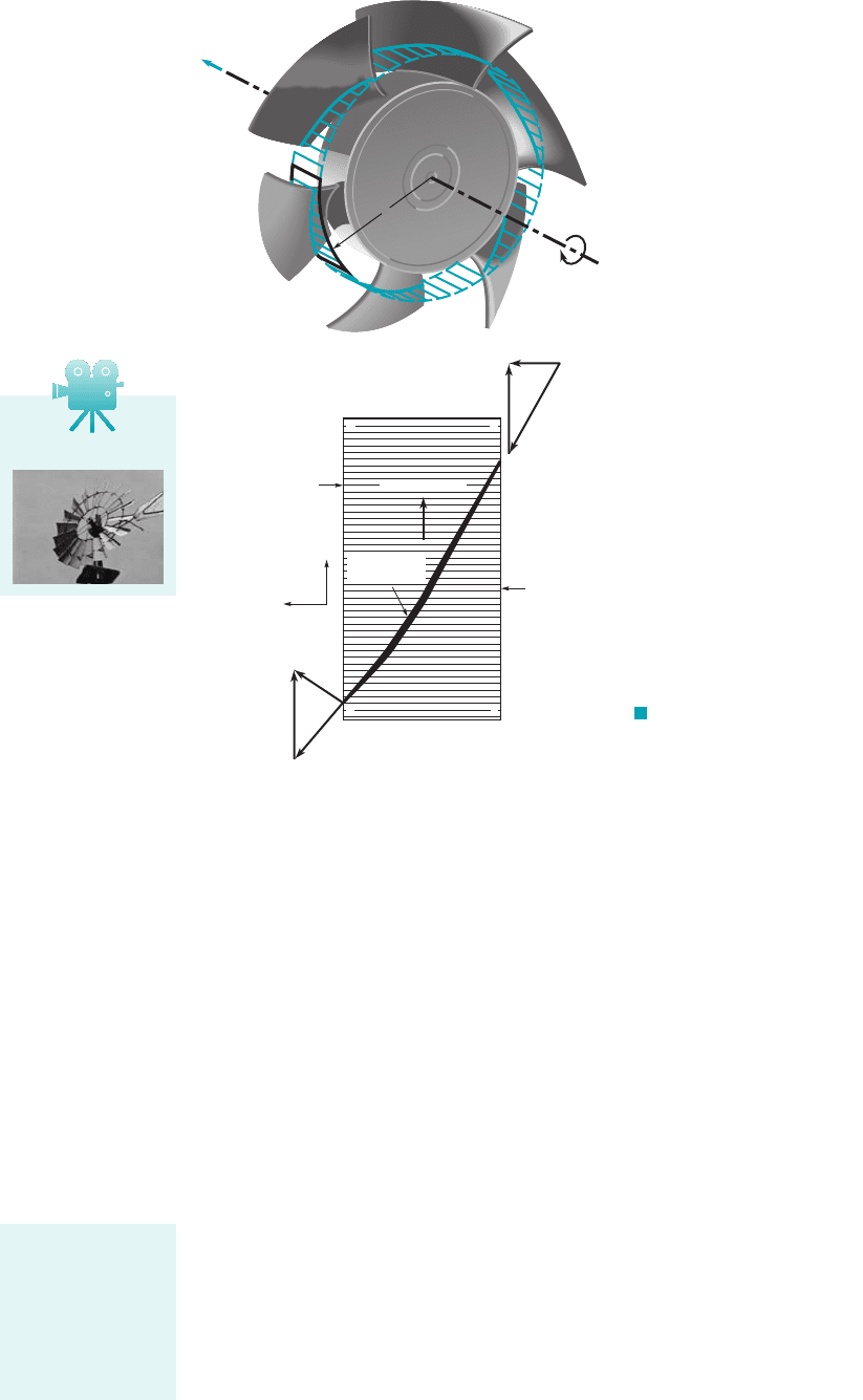
Consider a fan blade driven at constant angular velocity, , by a motor as is shown in Fig.
12.3a. We denote the blade speed as where r is the radial distance from the axis of the fan.
The absolute fluid velocity 1that seen by a person sitting stationary at the table on which the fan
rests2is denoted V, and the relative velocity 1that seen by a person riding on the fan blade2is de-
noted W. As shown by the figure in the margin, the actual 1absolute2fluid velocity is the vector sum
of the relative velocity and the blade velocity
(12.1)
A simplified sketch of the fluid velocity as it “enters” and “exits” the fan at radius r is
shown in Fig. 12.3b. The shaded surface labeled a–b–c–d is a portion of the cylindrical surface
1including a “slice” through the blade2shown in Fig. 12.3a. We assume for simplicity that the
V ⫽ W ⫹ U
U ⫽ vr,
v
V
U
W
A group of blades
moving with or
against a lift force
is the essence of a
turbomachine.
JWCL068_ch12_645-700.qxd 9/25/08 8:37 PM Page 647
flow moves smoothly along the blade so that relative to the moving blade the velocity is parallel
to the leading and trailing edges 1points 1 and 22of the blade. For now we assume that the fluid
enters and leaves the fan at the same distance from the axis of rotation; thus, In
actual turbomachines, the entering and leaving flows are not necessarily tangent to the blades,
and the fluid pathlines can involve changes in radius. These considerations are important at de-
sign and off-design operating conditions. Interested readers are referred to Refs. 1, 2, and 3 for
more information about these aspects of turbomachine flows.
With this information we can construct the velocity triangles shown in Fig. 12.3b. Note that
this view is from the top of the fan, looking radially down toward the axis of rotation. The motion
of the blade is up; the motion of the incoming air is assumed to be directed along the axis of rota-
tion. The important concept to grasp from this sketch is that the fan blade 1because of its shape and
motion2“pushes” the fluid, causing it to change direction. The absolute velocity vector, V, is turned
during its flow across the blade from section 112to section 122. Initially the fluid had no component
of absolute velocity in the direction of the motion of the blade, the 1or tangential2direction. When
the fluid leaves the blade, this tangential component of absolute velocity is nonzero. For this to oc-
cur, the blade must push on the fluid in the tangential direction. That is, the blade exerts a tangen-
tial force component on the fluid in the direction of the motion of the blade. This tangential force
component and the blade motion are in the same direction—the blade does work on the fluid. This
device is a pump.
On the other hand, consider the windmill shown in Fig. 12.4a. Rather than the rotor being
driven by a motor, the blades move in the direction of the lift force 1compared to the fan in Fig.
12.32exerted on each blade by the wind blowing through the rotor. We again note that because of
the blade shape and motion, the absolute velocity vectors at sections 112and 122, and haveV
2
,V
1
u
U
1
⫽ U
2
⫽ vr.
648 Chapter 12 ■ Turbomachines
F I G U R E 12.3 Idealized flow through
a fan: (a) fan blade geometry; (b) absolute velocity, V;
relative velocity, W; and blade velocity, U at the inlet
and exit of the fan blade section.
b
a
cd
Axial
Tangential
U
1
V
1
W
1
Blade motion
Inlet
surface
Exit surface
U
2
V
2
W
2
(2)
(1)
c
d
b
a
r
ω
(a)
(b)
Q
Blade cross
section
V12.1 Windmills
When blades move
because of the fluid
force, we have a
turbine; when
blades are forced to
move fluid, we have
a pump.
JWCL068_ch12_645-700.qxd 9/30/08 8:38 AM Page 648
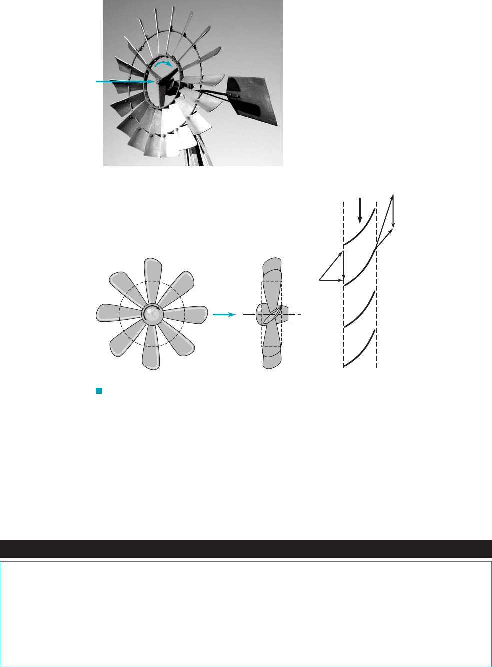
different directions. For this to happen, the blades must have pushed up on the fluid—opposite to the
direction of blade motion. Alternatively, because of equal and opposite forces 1action兾reaction2
the fluid must have pushed on the blades in the direction of their motion—the fluid does work on
the blades. This extraction of energy from the fluid is the purpose of a turbine.
These examples involve work transfer to or from a flowing fluid in two axial-flow turboma-
chines. Similar concepts hold for other turbomachines including mixed-flow and radial-flow con-
figurations.
12.2 Basic Energy Considerations 649
Fluids in the News
Current from currents The use of large, efficient wind turbines to
generate electrical power is becoming more commonplace through-
out the world. “Wind farms” containing numerous turbines located
at sites that have proper wind conditions can produce a significant
amount of electrical power. Recently, researchers in the United
States, the United Kingdom and Canada have been investigating the
possibility of harvesting the power of ocean currents and tides by us-
ing current turbines that function much like wind turbines. Rather
than being driven by wind, they derive energy from ocean currents
that occur at many locations in the 70% of the earth’s surface that
is water. Clearly, a 4-knot (2.5 m兾s) tidal current is not as fast as
a 40-mph (70 km兾hr) wind driving a wind turbine. However,
since turbine power output is proportional to the fluid density, and
since seawater is more than 800 times as dense as air, significant
power can be extracted from slow, but massive, ocean currents.
One promising configuration involves blades twisted in a helical
pattern. This technology may provide electrical power that is both
ecologically and economically sound. (See Problem 12.6.)
F I G U R E 12.4 Idealized flow through a windmill: (a) windmill;
(b) windmill blade geometry; (c) absolute velocity, V; relative velocity, W; and blade
velocity, U; at the inlet and exit of the windmill blade section.
(2)(1)
ω
(b)(c)
Blade motion
(2)
(1)
U
2
V
2
W
2
U
1
V
1
W
1
(a)
JWCL068_ch12_645-700.qxd 9/25/08 8:37 PM Page 649
650 Chapter 12 ■ Turbomachines
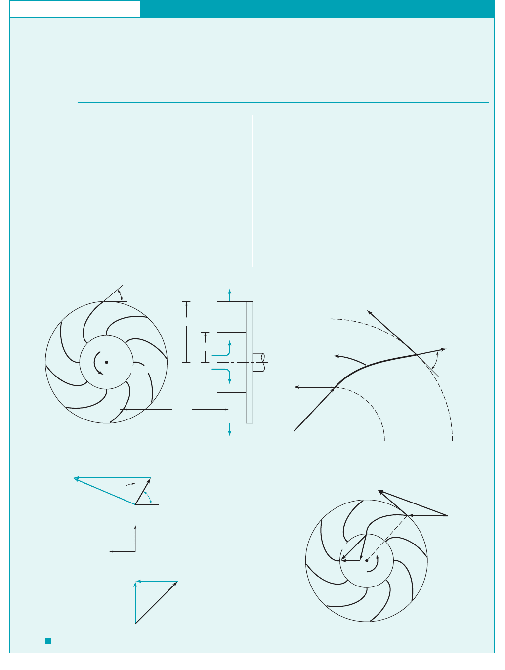
GIVEN The rotor shown in Fig. E12.1a rotates at a constant
angular velocity of Although the fluid initially
approaches the rotor in an axial direction, the flow across the
blades is primarily outward 1see Fig. 12.2a2. Measurements
v ⫽ 100 rad
Ⲑ
s.
Basic Difference between a Pump and a Turbine
E
XAMPLE 12.1
S
OLUTION
To answer this question, we need to know if the tangential com-
ponent of the force of the blade on the fluid is in the direction of
the blade motion 1a pump2or opposite to it 1a turbine2. We assume
that the blades are tangent to the incoming relative velocity and
that the relative flow leaving the rotor is tangent to the blades as
shown in Fig. E12.1b. We can also calculate the inlet and outlet
blade speeds as
and
With the known, absolute fluid velocity and blade velocity at
the inlet, we can draw the velocity triangle 1the graphical repre-
sentation of Eq. 12.12at that location as shown in Fig. E12.1c.
U
2
⫽ vr
2
⫽ 1100 rad
Ⲑ
s210.2 m2⫽ 20 m
Ⲑ
s
U
1
⫽ vr
1
⫽ 1100 rad
Ⲑ
s210.1 m2⫽ 10 m
Ⲑ
s
indicate that the absolute velocity at the inlet and outlet are
and respectively.
FIND Is this device a pump or a turbine?
V
2
⫽ 15 m
Ⲑ
s,V
1
⫽ 12 m
Ⲑ
s
Blade
(1)
(2)
(1)
(2)
= 60°
β
= 100 rad/s
ω
r
2
= 0.2m
r
1
= 0.1m
2
(a)
F I G U R E E12.1
ω
U
2
W
2
W
1
V
1
U
1
V
2
(d)
W
2
U
2
= 20 m/s
V
2
= 15 m/s
= 60°
β
2
30°
Radial
Circumferential
W
1
V
1
= 12 m/s
U
1
= 10 m/s
Outlet
Known quantities
shown in color
Inlet
(c)
(1)
(2)
60°
W
2
U
2
= 20 m/s
Blade
motion
W
1
U
1
= 10 m/s
+
(b)
Note that we have assumed that the absolute flow at the blade
row inlet is radial 1i.e., the direction of is radial2. At the out-
let we know the blade velocity, the outlet speed, and the rel-
ative velocity direction, 1because of the blade geometry2. There-
fore, we can graphically 1or trigonometrically2construct the outlet
velocity triangle as shown in the figure. By comparing the velocity
triangles at the inlet and outlet, it can be seen that as the fluid flows
across the blade row, the absolute velocity vector turns in the di-
rection of the blade motion. At the inlet there is no component
of absolute velocity in the direction of rotation; at the outlet this
component is not zero. That is, the blade pushes and turns the
fluid in the direction of the blade motion, thereby doing work on
the fluid, adding energy to it.
This device is a pump.
(Ans)
b
2
V
2
,U
2
,
V
1
JWCL068_ch12_645-700.qxd 9/25/08 8:37 PM Page 650

12.3 Basic Angular Momentum Considerations 651
12.3 Basic Angular Momentum Considerations
In the previous section we indicated how work transfer to or from a fluid flowing through a pump
or a turbine occurs by interaction between moving rotor blades and the fluid. Since all of these
turbomachines involve the rotation of an impeller or a rotor about a central axis, it is appropriate
to discuss their performance in terms of torque and angular momentum.
Recall that work can be written as force times distance or as torque times angular dis-
placement. Hence, if the shaft torque 1the torque that the shaft applies to the rotor2and the ro-
tation of the rotor are in the same direction, energy is transferred from the shaft to the rotor
and from the rotor to the fluid—the machine is a pump. Conversely, if the torque exerted by
the shaft on the rotor is opposite to the direction of rotation, the energy transfer is from the
fluid to the rotor—a turbine. The amount of shaft torque 1and hence shaft work2can be obtained
from the moment-of-momentum equation derived formally in Section 5.2.3 and discussed as
follows.
Consider a fluid particle traveling outward through the rotor in the radial-flow machine shown
in Figs. E12.1a, b, and c. For now, assume that the particle enters the rotor with a radial velocity
only 1i.e., no “swirl”2. After being acted upon by the rotor blades during its passage from the inlet
[section 112] to the outlet [section 122], this particle exits with radial 1r2and circumferential com-
ponents of velocity. Thus, the particle enters with no angular momentum about the rotor axis of
rotation but leaves with nonzero angular momentum about that axis. 1Recall that the axial compo-
nent of angular momentum for a particle is its mass times the distance from the axis times the
component of absolute velocity.2
A similar experience can occur at the neighborhood playground. Consider yourself as a par-
ticle and a merry-go-round as a rotor. Walk from the center to the edge of the spinning merry-
go-round and note the forces involved. The merry-go-round does work on you—there is a “side-
ward force” on you. Another person must apply a torque 1and power2to the merry-go-round to
maintain a constant angular velocity, otherwise the angular momentum of the system 1you and the
merry-go-round2is conserved and the angular velocity decreases as you increase your distance
from the axis of rotation. 1Similarly, if the motor driving a pump is turned off, the pump will ob-
viously slow down and stop.2Your friend is the motor supplying energy to the rotor that is trans-
ferred to you. Is the amount of energy your friend expends to keep the angular velocity constant
dependent upon what path you follow along the merry-go-round 1i.e., the blade shape2; on how
fast and in what direction you walk off the edge 1i.e., the exit velocity2; on how much you weigh
1i.e., the density of the fluid2? What happens if you walk from the outside edge toward the cen-
ter of the rotating merry-go-round? Recall that the opposite of a pump is a turbine.
In a turbomachine a series of particles 1a continuum2passes through the rotor. Thus, the mo-
ment-of-momentum equation applied to a control volume as derived in Section 5.2.3 is valid. For
steady flow 1or for turbomachine rotors with steady-in-the-mean or steady-on-average cyclical
flow2, Eq. 5.42 gives
Recall that the left-hand side of this equation represents the sum of the external torques 1moments2
acting on the contents of the control volume, and the right-hand side is the net rate of flow of mo-
ment-of-momentum 1angular momentum2through the control surface.
a
1r ⫻ F2⫽
冮
cs
1r ⫻ V2 rV ⴢ nˆ dA
u
1u2
COMMENT On the other hand, by reversing the direction
of flow from larger to smaller radii, this device can become a
radial-flow turbine. In this case 1Fig. E12.1d2the flow direction
is reversed 1compared to that in Figs. E12.1a, b, and c2and the
velocity triangles are as indicated. Stationary vanes around the
perimeter of the rotor would be needed to achieve as shown.
Note that the component of the absolute velocity, V, in the di-
V
1
rection of the blade motion is smaller at the outlet than at the
inlet. The blade must push against the fluid in the direction op-
posite the motion of the blade to cause this. Hence 1by equal
and opposite forces2, the fluid pushes against the blade in the
direction of blade motion, thereby doing work on the blade.
There is a transfer of work from the fluid to the blade—a
turbine operation.
When shaft torque
and rotation are in
the same direction,
we have a pump;
otherwise we have a
turbine.
V12.2 Self-
propelled lawn
sprinkler
JWCL068_ch12_645-700.qxd 9/25/08 8:37 PM Page 651
The axial component of this equation applied to the one-dimensional simplification of flow
through a turbomachine rotor with section 112as the inlet and section 122as the outlet results in
(12.2)
where is the shaft torque applied to the contents of the control volume. The is associated
with mass flowrate into the control volume and the is used with the outflow. The sign of the
component depends on the direction of and the blade motion, U. If and U are in the same di-
rection, then is positive. The sign of the torque exerted by the shaft on the rotor, is positive
if is in the same direction as rotation, and negative otherwise.
As seen from Eq. 12.2, the shaft torque is directly proportional to the mass flowrate,
1It takes considerably more torque and power to pump water than to pump air with the same vol-
ume flowrate.2The torque also depends on the tangential component of the absolute velocity,
Equation 12.2 is often called the Euler turbomachine equation.
Also recall that the shaft power, is related to the shaft torque and angular velocity by
(12.3)
By combining Eqs. 12.2 and 12.3 and using the fact that we obtain
(12.4)
Again, the value of is positive when and U are in the same direction and negative otherwise.
Also, is positive when the shaft torque and are in the same direction and negative other-
wise. Thus, is positive when power is supplied to the contents of the control volume 1pumps2
and negative otherwise 1turbines2. This outcome is consistent with the sign convention involving
the work term in the energy equation considered in Chapter 5 1see Eq. 5.672.
Finally, in terms of work per unit mass, we obtain
(12.5)
where we have used the fact that by conservation of mass, Equations 12.3, 12.4, and 12.5
are the basic governing equations for pumps or turbines whether the machines are radial-, mixed-,
or axial-flow devices and for compressible and incompressible flows. Note that neither the axial
nor the radial component of velocity enter into the specific work 1work per unit mass2equation.
[In the above merry-go-round example the amount of work your friend does is independent of how
fast you jump “up” 1axially2or “out” 1radially2as you exit. The only thing that counts is your
component of velocity.]
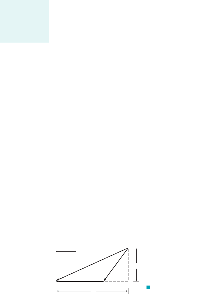
Another useful but more laborious form of Eq. 12.5 can be obtained by writing the right-
hand side in a slightly different form based on the velocity triangles at the entrance or exit as shown
generically in Fig. 12.5. The velocity component is the generic through-flow component of ve-
locity and it can be axial, radial, or in-between depending on the rotor configuration. From the
large right triangle we note that
or
(12.6)V
2
x
V
2
V
2
u
V
2
V
2
u
V
2
x
V
x
u
m
#
1
m
#
2
.
w
shaft
U
1
V
u1
U
2
V
u2
w
shaft
W
#
shaft
m
#
,
W
#
shaft
vW
#
shaft
V
u
V
u
W
#
shaft
m
1
#
1U
1
V
u1
2 m
#
2
1U
2
V
u2
2
U vr,
W
#
shaft
T
shaft
v
W
#
shaft
,
V
u
.
m
#
rQ.
T
shaft
T
shaft
,V
u
V
u
V
u
V
u
“ ”
“”
T
shaft
T
shaft
m
#
1
1r
1
V
u1
2 m
#
2
1r
2
V
u2
2
652 Chapter 12 ■ Turbomachines
F I G U R E 12.5 Velocity triangle: V
absolute velocity, W relative velocity, U blade velocity.ⴝⴝ
ⴝ
U
V
W
θ
V
x
V
θ
x
The Euler turboma-
chine equation is the
axial component of
the moment-
of-momentum
equation.
JWCL068_ch12_645-700.qxd 9/25/08 8:37 PM Page 652

From the small right triangle we note that
(12.7)
By combining Eqs. 12.6 and 12.7 we obtain
which when written for the inlet and exit and combined with Eq. 12.5 gives
(12.8)
Thus, the power and the shaft work per unit mass can be obtained from the speed of the blade, U,
the absolute fluid speed, V, and the fluid speed relative to the blade, W. This is an alternative to us-
ing fewer components of the velocity as suggested by Eq. 12.5. Equation 12.8 contains more terms
than Eq. 12.5; however, it is an important concept equation because it shows how the work trans-
fer is related to absolute, relative, and blade velocity changes. Because of the general nature of the
velocity triangle in Fig. 12.5, Eq. 12.8 is applicable for axial-, radial-, and mixed-flow rotors.
w
shaft
V
2
2
V
2
1
U
2
2
U
2
1
1W
2
2
W
2
1
2
2
V
u
U
V
2
U
2
W
2
2
V
2
x
1V
u
U2
2
W
2
12.4 The Centrifugal Pump 653
Fluids in the News
1948 Buick Dynaflow started it Prior to 1948 almost all cars had
manual transmissions which required the use of a clutch pedal to
shift gears. The 1948 Buick Dynaflow was the first automatic
transmission to use the hydraulic torque converter and was
the model for present-day automatic transmissions. Currently, in
the U.S. over 84% of the cars have automatic transmissions. The
torque converter replaces the clutch found on manual shift vehicles
and allows the engine to continue running when the vehicle comes
to a stop. In principle, but certainly not in detail or complexity, op-
eration of a torque converter is similar to blowing air from a fan
onto another fan which is unplugged. One can hold the blade of
the unplugged fan and keep it from turning, but as soon as it is let
go, it will begin to speed up until it comes close to the speed of the
powered fan. The torque converter uses transmission fluid (not air)
and consists of a pump (the powered fan) driven by the engine
drive shaft, a turbine (the unplugged fan) connected to the input
shaft of the transmission, and a stator (absent in the fan model) to
efficiently direct the flow between the pump and turbine.
12.4 The Centrifugal Pump
F I G U R E 12.6 Schematic
diagram of basic elements of a
centrifugal pump.
(a)
Discharge
Impeller
Eye
Inflow
Blade
Hub plate
Casing, housing,
or volute
(b)
One of the most common radial-flow turbomachines is the centrifugal pump. This type of pump
has two main components: an impeller attached to a rotating shaft, and a stationary casing, hous-
ing, or volute enclosing the impeller. The impeller consists of a number of blades 1usually curved2,
also sometimes called vanes, arranged in a regular pattern around the shaft. A sketch showing
the essential features of a centrifugal pump is shown in Fig. 12.6. As the impeller rotates, fluid
is sucked in through the eye of the casing and flows radially outward. Energy is added to the
fluid by the rotating blades, and both pressure and absolute velocity are increased as the fluid
flows from the eye to the periphery of the blades. For the simplest type of centrifugal pump, the
Turbomachine work
is related to
changes in absolute,
relative, and blade
velocities.
JWCL068_ch12_645-700.qxd 9/25/08 8:37 PM Page 653
fluid discharges directly into a volute-shaped casing. The casing shape is designed to reduce the
velocity as the fluid leaves the impeller, and this decrease in kinetic energy is converted into an
increase in pressure. The volute-shaped casing, with its increasing area in the direction of flow,
is used to produce an essentially uniform velocity distribution as the fluid moves around the cas-
ing into the discharge opening. For large centrifugal pumps, a different design is often used in
which diffuser guide vanes surround the impeller. The diffuser vanes decelerate the flow as the
fluid is directed into the pump casing. This type of centrifugal pump is referred to as a diffuser
pump.
Impellers are generally of two types. For one configuration the blades are arranged on a hub
or backing plate and are open on the other 1casing or shroud2side. A typical open impeller is shown
in Fig. 12.7a. For the second type of impeller, called an enclosed or shrouded impeller, the blades
are covered on both hub and shroud ends as shown in Fig. 12.7b.
Pump impellers can also be single or double suction. For the single-suction impeller the fluid
enters through the eye on only one side of the impeller, whereas for the double-suction impeller
the fluid enters the impeller along its axis from both sides. The double-suction arrangement re-
duces end thrust on the shaft, and also, since the net inlet flow area is larger, inlet velocities are
reduced.
Pumps can be single or multistage. For a single-stage pump, only one impeller is mounted on
the shaft, whereas for multistage pumps, several impellers are mounted on the same shaft. The stages
operate in series, that is, the discharge from the first stage flows into the eye of the second stage, the
discharge from the second stage flows into the eye of the third stage, and so on. The flowrate is the
same through all stages, but each stage develops an additional pressure rise. Thus, a very large dis-
charge pressure, or head, can be developed by a multistage pump.
Centrifugal pumps come in a variety of arrangements 1open or shrouded impellers, volute
or diffuser casings, single- or double-suction, single- or multistage2, but the basic operating prin-
ciple remains the same. Work is done on the fluid by the rotating blades 1centrifugal action and
tangential blade force acting on the fluid over a distance2, creating a large increase in kinetic en-
ergy of the fluid flowing through the impeller. This kinetic energy is converted into an increase
in pressure as the fluid flows from the impeller into the casing enclosing the impeller. A simpli-
fied theory describing the behavior of the centrifugal pump was introduced in the previous sec-
tion and is expanded in the following section.
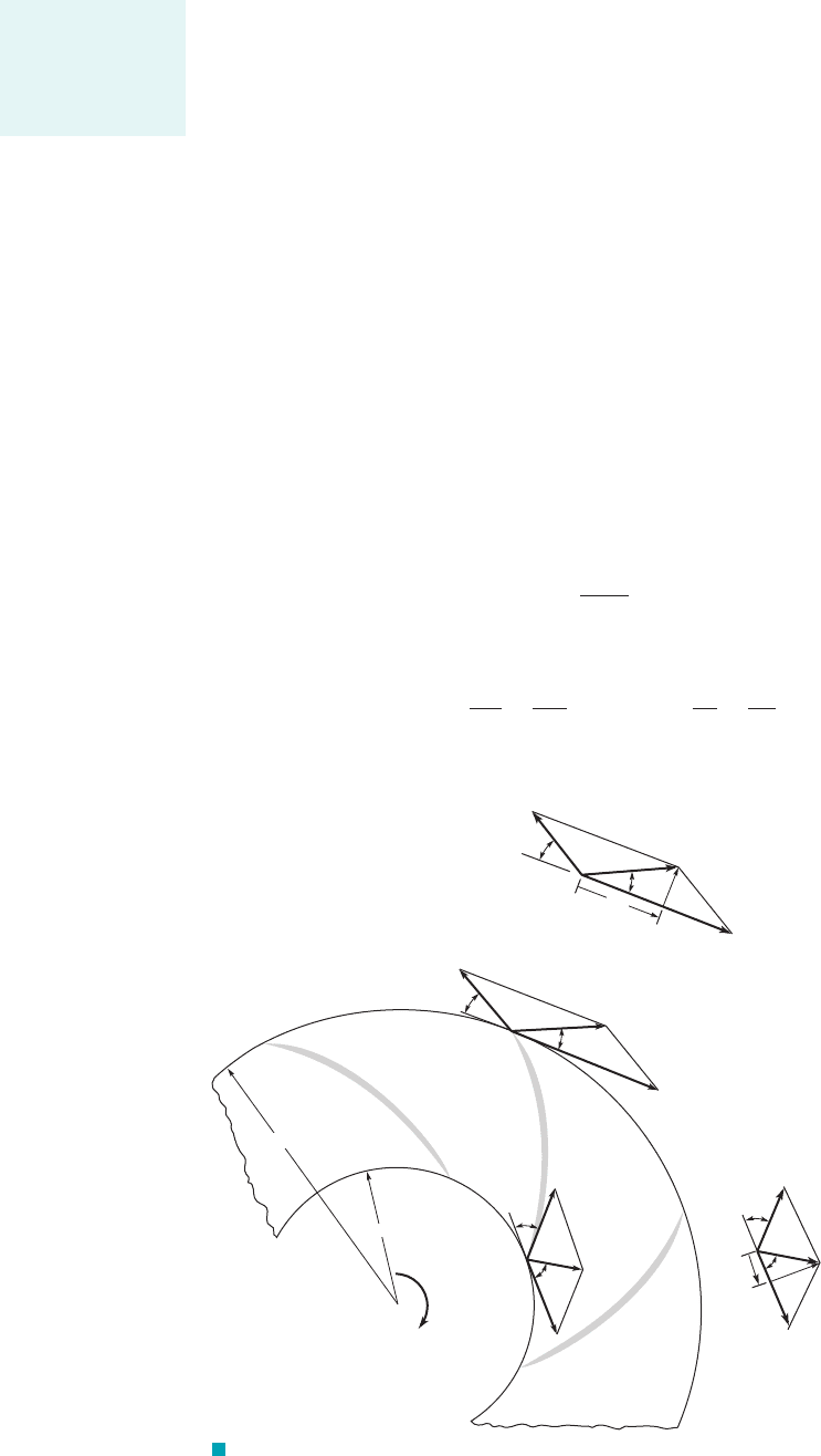
12.4.1 Theoretical Considerations
Although flow through a pump is very complex 1unsteady and three-dimensional2, the basic theory of
operation of a centrifugal pump can be developed by considering the average one-dimensional flow of
the fluid as it passes between the inlet and the outlet sections of the impeller as the blades rotate. As
shown in Fig. 12.8, for a typical blade passage, the absolute velocity, of the fluid entering the pas-
sage is the vector sum of the velocity of the blade, rotating in a circular path with angular veloc-
ity and the relative velocity, within the blade passage so that Similarly, at the
exit Note that and Fluid velocities are taken to be average
velocities over the inlet and exit sections of the blade passage. The relationship between the various
velocities is shown graphically in Fig. 12.8.
U
2
⫽ r
2
v.U
1
⫽ r
1
vV
2
⫽ W
2
⫹ U
2
.
V
1
⫽ W
1
⫹ U
1
.W
1
,v,
U
1
,
V
1
,
654 Chapter 12 ■ Turbomachines
Centrifugal pumps
involve radially
outward flows.
F I G U R E 12.7
(a) Open impeller, (b) enclosed
or shrouded impeller.
(Courtesy of Ingersoll-Dresser
Pump Company.)
JWCL068_ch12_645-700.qxd 9/25/08 8:38 PM Page 654
As discussed in Section 12.3, the moment-of-momentum equation indicates that the shaft
torque, required to rotate the pump impeller is given by equation Eq. 12.2 applied to a pump
with That is,
(12.9)
or
(12.10)
where and are the tangential components of the absolute velocities, and 1see Figs.
12.8b,c2.
For a rotating shaft, the power transferred, is given by
and therefore from Eq. 12.10
Since and we obtain
(12.11)
Equation 12.11 shows how the power supplied to the shaft of the pump is transferred to the flow-
ing fluid. It also follows that the shaft power per unit mass of flowing fluid is
(12.12)
For incompressible pump flow, we get from Eq. 5.82
w
shaft
a
p
out
r
V
out
2
2
gz
out
b a
p
in
r
V
in
2
2
gz
in
b loss
w
shaft
W
#
shaft
rQ
U
2
V
u2
U
1
V
u1
W
#
shaft
rQ1U
2
V
u2
U
1
V
u1
2
U
2
r
2
vU
1
r
1
v
W
#
shaft
rQv1r
2
V
u2
r
1
V
u1
2
W
#
shaft
T
shaft
v
W
#
shaft
,
V
2
V
1
V
u2
V
u1
T
shaft
rQ1r
2
V
u2
r
1
V
u1
2
T
shaft
m
#
1r
2
V
u2
r
1
V
u1
2
m
#
1
m
#
2
m
#
.
T
shaft
,
12.4 The Centrifugal Pump 655
V
2
U
2
W
2
U
2
V
2
W
2
V
r2
2
β
α
2
W
1
V
1
U
1
V
1
θ
V
r1
1
β
α
1
U
1
W
1
V
1
+
ω
r
1
r
2
1
β
α
1
(a)
(b)
(c)
2
β
α
2
V
2
θ
F I G U R E 12.8 Velocity diagrams at the inlet and exit of a
centrifugal pump impeller.
Centrifugal pump
impellers involve an
increase in blade
velocity along the
flow path.
JWCL068_ch12_645-700.qxd 9/25/08 8:38 PM Page 655

Combining Eq. 12.12 with this, we get
Dividing both sides of this equation by the acceleration of gravity, g, we obtain
where H is total head defined by
and h
L
is head loss.
From this equation we see that is the shaft work head added to the fluid by the
pump. Head loss, h
L
, reduces the actual head rise, , achieved by the fluid. Thus, the ideal
head rise possible, h
i
, is
(12.13)
The actual head rise, , is always less than the ideal head rise, h
i
, by an amount
equal to the head loss, h
L
, in the pump. Some additional insight into the meaning of Eq. 12.13 can
be obtained by using the following alternate version 1see Eq. 12.82.
(12.14)
A detailed examination of the physical interpretation of Eq. 12.14 would reveal the following. The
first term in brackets on the right-hand side represents the increase in the kinetic energy of the
fluid, and the other two terms represent the pressure head rise that develops across the impeller
due to the centrifugal effect, and the diffusion of relative flow in the blade passages,
An appropriate relationship between the flowrate and the pump ideal head rise can be ob-
tained as follows. Often the fluid has no tangential component of velocity or swirl, as it en-
ters the impeller; that is, the angle between the absolute velocity and the tangential direction is
1 in Fig. 12.82. In this case, Eq. 12.13 reduces to
(12.15)
From Fig. 12.8c
so that Eq. 12.15 can be expressed as
(12.16)
The flowrate, Q, is related to the radial component of the absolute velocity through the equation
(12.17)
where is the impeller blade height at the radius Thus, combining Eqs. 12.16 and 12.17 yields
(12.18)
This equation is graphed in the margin and shows that the ideal or maximum head rise for a cen-
trifugal pump varies linearly with Q for a given blade geometry and angular velocity. For actual
h
i
U
2
2
g
U
2
cot b
2
2pr
2
b
2
g
Q
r
2
.b
2
Q 2pr
2
b
2
V
r2
h
i
U
2
2
g
U
2
V
r2
cot b
2
g
cot b
2
U
2
V
u2
V
r2
h
i
U
2
V
u2
g
a
1
90°
90°
V
u1
,
W
1
2
W
2
2
.
U
2
2
U
1
2
,
h
i
1
2g
31V
2
2
V
1
2
2 1U
2
2
U
1
2
2 1W
1
2
W
2
2
24
H
out
H
in
h
a
h
i
U
2
V
u2
U
1
V
u1
g
H
out
H
in
1U
2
V
u2
U
1
V
u1
2
g
H
p
rg
V
2
2g
z
U
2
V
u 2
U
1
V
u1
g
H
out
H
in
h
L
a
p
out
r
V
out
2
2
gz
out
b a
p
in
r
V
in
2
2
gz
in
b lossU
2
V
u2
U
1
V
u1
656 Chapter 12 ■ Turbomachines
The pump actual
head rise is less
than the pump ideal
head rise by an
amount equal to the
head loss in the
pump.
h
i
Q
JWCL068_ch12_645-700.qxd 9/25/08 8:38 PM Page 656