Munson B.R. Fundamentals of Fluid Mechanics
Подождите немного. Документ загружается.

Problems 697
Fig. 12.14. For what is the expected flowrate if the
total length of constant diameter pipe is 600 ft and the fluid is wa-
ter? Assume the pipe diameter to be 4 in. and the friction factor to
be equal to 0.02. Neglect all minor losses.
12.35 A centrifugal pump having a 6-in.-diameter impeller and
the characteristics shown in Fig. 12.12 is to be used to pump gaso-
line through 4000 ft of commercial steel 3-in.-diameter pipe. The
pipe connects two reservoirs having open surfaces at the same
elevation. Determine the flowrate. Do you think this pump is a
good choice? Explain.
12.36 Determine the new flowrate for the system described in
Problem 12.35 if the pipe diameter is increased from 3 in. to 4 in.
Is this pump still a good choice? Explain.
12.37 A centrifugal pump having the characteristics shown in
Example 12.4 is used to pump water between two large open tanks
through 100 ft of 8-in.-diameter pipe. The pipeline contains 4 reg-
ular flanged elbows, a check valve, and a fully open globe
valve. Other minor losses are negligible. Assume the friction fac-
tor for the 100-ft section of pipe. If the static head 1dif-
ference in height of fluid surfaces in the two tanks2is 30 ft, what
is the expected flowrate? Do you think this pump is a good choice?
Explain.
12.38 In a chemical processing plant a liquid is pumped from an
open tank, through a 0.1-m-diameter vertical pipe, and into another
open tank as shown in Fig. P12.381a2. A valve is located in the
pipe, and the minor loss coefficient for the valve as a function of
the valve setting is shown in Fig. P12.381b2. The pump head-
capacity relationship is given by the equation
with in meters when Q is in m
3
s. Assume the friction
Ⲑ
h
a
10
3
Q
2
h
a
⫽ 52.0 ⫺ 1.01 ⫻
f ⫽ 0.02
90°
z
2
⫺ z
1
⫽ 50 ft,
factor f 0.02 for the pipe, and all minor losses, except for the
valve, are negligible. The fluid levels in the two tanks can be as-
sumed to remain constant. (a)Determine the flowrate with the valve
wide open. (b) Determine the required valve setting 1percent open2
to reduce the flowrate by 50%.
†12.39 Water is pumped between the two tanks described in Ex-
ample 12.4 once a day, 365 days a year, with each pumping pe-
riod lasting two hours. The water levels in the two tanks remain
essentially constant. Estimate the annual cost of the electrical power
needed to operate the pump if it were located in your city. You will
have to make a reasonable estimate for the efficiency of the motor
used to drive the pump. Due to aging, it can be expected that the
overall resistance of the system will increase with time. If the op-
erating point shown in Fig. E12.4c changes to a point where the
flowrate has been reduced to 1000 gpm, what will be the new an-
nual cost of operating the pump? Assume that the cost of electri-
cal power remains the same.
Section 12.5 Dimensionless Parameters and
Similarity Laws
12.40 Obtain photographs images of a series of production pump
rotors that suggest they are geometrically similar though different
in feature size.
12.41 What is the rationale for operating two geometrically sim-
ilar pumps differing in feature size at the same flow coefficient?
12.42 A centrifugal pump having an impeller diameter of 1 m is
to be constructed so that it will supply a head rise of 200 m at a
flowrate of of water when operating at a speed of 1200 rpm.
To study the characteristics of this pump, a scale, geometri-
cally similar model operated at the same speed is to be tested in
the laboratory. Determine the required model discharge and head
rise. Assume that both model and prototype operate with the same
efficiency 1and therefore the same flow coefficient2.
12.43 A centrifugal pump with a 12-in.-diameter impeller requires
a power input of 60 hp when the flowrate is 3200 gpm against a
60-ft head. The impeller is changed to one with a 10-in. diame-
ter. Determine the expected flowrate, head, and input power if the
pump speed remains the same.
12.44 Do the head-flowrate data shown in Fig. 12.12 appear to
follow the similarity laws as expressed by Eqs. 12.39 and 12.40?
Explain.
12.45 A centrifugal pump has the performance characteristics
of the pump with the 6-in.-diameter impeller described in Fig.
12.12. Note that the pump in this figure is operating at 3500 rpm.
What is the expected head gained if the speed of this pump is
reduced to 2800 rpm while operating at peak efficiency?
12.46 A centrifugal pump provides a flowrate of 500 gpm when
operating at 1750 rpm against a 200-ft head. Determine the pump’s
flowrate and developed head if the pump speed is increased to
3500 rpm.
12.47 Explain how Fig. 12.18 was constructed from test data. Why
is this use of specific speed important? Illustrate with a specific
example.
12.48 Use the data given in Problem 12.25 and plot the dimen-
sionless coefficients versus for this pump. Calculate
a meaningful value of specific speed, discuss its usefulness, and
compare the result with data of Fig. 12.18.
12.49 In a certain application a pump is required to deliver 5000
gpm against a 300-ft head when operating at 1200 rpm. What type
of pump would you recommend?
C
Q
C
H
, C
p
, h
1
Ⲑ
5
4.1 m
3
Ⲑ
s
Ⲑ
⫽
F I G U R E P12.38
0
20 40 60 80 100
10
20
30
40
0
(Open)
(Closed)
Percent valve setting
Valve
D = 0.1 m
Open
Pump
K
L
30 m
3 m
(a)
(b)
JWCL068_ch12_645-700.qxd 9/25/08 8:51 PM Page 697
698 Chapter 12 ■ Turbomachines
Section 12.6 Axial-Flow and Mixed-Flow Pumps
12.50 Obtain photographs images of a variety of axial-flow and
mixed-flow pump rotors. Explain any unusual features.
12.51 (See Fluids in the News Article titled “Mechanical heart as-
sist devices” Section 12.6.) Obtain photographs images of blood
flow pumps that are turbomachines.
12.52 Explain how a marine propeller and an axial-flow pump are
similar in the main effect they produce.
12.53 A certain axial-flow pump has a specific speed of
If the pump is expected to deliver 3000 gpm when operating against
a 15-ft head, at what speed 1rpm2should the pump be run?
12.54 A certain pump is known to have a capacity of when
operating at a speed of 60 rad s against a head of 20 m. Based on
the information in Fig. 12.18, would you recommend a radial-flow,
mixed-flow, or axial-flow pump?
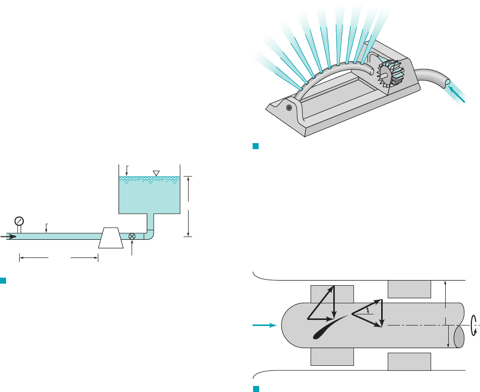
12.55 Fuel oil
is pumped through the piping system of Fig. P12.55 with a
velocity of 4.6 ft s. The pressure 200 ft upstream from the pump
is 5 psi. Pipe losses downstream from the pump are negligible, but
minor losses are not 1minor loss coefficients are given on the fig-
ure2. (a) For a pipe diameter of 2 in. with a relative roughness
determine the head that must be added by the pump.
(b) For a pump operating speed of 1750 rpm, what type of pump
1radial-flow, mixed-flow, or axial-flow2would you recommend for
this application?
e
Ⲑ
D ⫽ 0.001,
Ⲑ
s
Ⲑ
ft
2
2
1sp. wt ⫽ 48.0 lb
Ⲑ
ft
3
, viscosity ⫽ 2.0 ⫻ 10
⫺5
lb
#
Ⲑ
3 m
3
Ⲑ
s
N
S
⫽ 5.0.
Ⲑ
Ⲑ
12.61 Consider the Pelton wheel turbine illustrated in Figs. 12.24,
12.25, 12.26, and 12.27. This kind of turbine is used to drive the
oscillating sprinkler shown in Video V12.3. Explain how this kind
of sprinkler is started, and subsequently operated at constant oscil-
lating speed. What is the physical significance of the zero torque
condition with the Pelton wheel rotating?
12.62 A small Pelton wheel is used to power an oscillating lawn
sprinkler as shown in Video V12.3 and Fig. P12.62. The arithmetic
mean radius of the turbine is 1 in., and the exit angle of the blade
is 135° relative to the blade motion. Water is supplied through a
single 0.20-in.-diameter nozzle at a speed of Determine the
flowrate, the maximum torque developed, and the maximum power
developed by this turbine.
50 ft
Ⲑ
s.
F I G U R E P12.55
D = 2 in.
Valve
Pump
(K
L
= 10.0)
(K
L
= 1.5)
Elbow
(K
L
= 1.0)
Exit
V = 4.6 ft/s
5 psi
Open
200 ft
20 ft
12.56 The axial-flow pump shown in Fig. 12.19 is designed to
move of water over a head rise of 5 ft of water. Es-
timate the motor power requirement and the needed to achieve
this flowrate on a continuous basis. Comment on any cautions as-
sociated with where the pump is placed vertically in the pipe.
Section 12.7 Fans
12.57 Obtain photographs images of a variety of fan rotors and
categorize them as axial-flow, radial-flow, or mixed-flow fans. Note
any unusual features.
12.58 (See Fluids in the News Article titled “High-tech ceiling
fans,” Section 12.7.) Explain why reversing the direction of rota-
tion of a ceiling fan results in airflow in the opposite direction.
12.59 For the fan of both Examples 5.19 and 5.28 discuss what
fluid flow properties you would need to measure to estimate fan
efficiency.
Section 12.8 Turbines
12.60 Obtain photographs images of very small and very large
turbine rotors, and explain briefly where each is used.
Ⲑ
Ⲑ
U
2
V
u2
5000 gal
Ⲑ
min
F I G U R E P12.62
Q
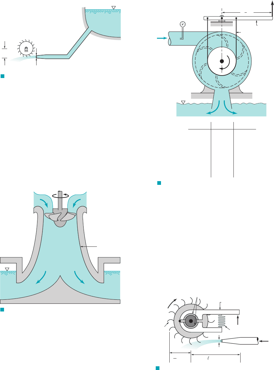
12.63 The single-stage, axial-flow turbomachine shown in Fig.
P12.63 involves water flow at a volumetric flowrate of 9 m
3
兾s. The
rotor revolves at 600 rpm. The inner and outer radii of the annu-
lar flow path through the stage are 0.46 and 0.61 m, and .
The flow entering the rotor row and leaving the stator row is ax-
ial when viewed from the stationary casing. Is this device a tur-
bine or a pump? Estimate the amount of power transferred to or
from the fluid.
b
2
⫽ 60°
F I G U R E P12.63
600
rpm
r
1
= 0.46 m
r
0
= 0.61 m
Q =
9 m
3
/s
β
2
W
2
U
2
V
2
V
1
U
1
W
1
12.64 Describe what will happen when the flow through the tur-
bomachine of Fig. P12.63 is in the opposite direction (right to left)
and the shaft is freed up to rotate in response to the reversed flow.
12.65 For an air turbine of a dentist’s drill like the one shown in
Fig. E12.8 and Video V12.4, calculate the average blade speed as-
sociated with a rotational speed of 350,000 rpm. Estimate the air
pressure needed to run this turbine.
12.66 Water for a Pelton wheel turbine flows from the headwater
and through the penstock as shown in Fig. P12.66. The effective
friction factor for the penstock, control valves, and the like is 0.032
JWCL068_ch12_645-700.qxd 9/25/08 8:51 PM Page 698
and the diameter of the jet is 0.20 m. Determine the maximum
power output.
12.67 Water to run a Pelton wheel is supplied by a penstock of length
and diameter D with a friction factor f. If the only losses associ-
ated with the flow in the penstock are due to pipe friction, show that
the maximum power output of the turbine occurs when the nozzle di-
ameter, is given by
12.68 A hydraulic turbine operating at 180 rpm with a head of
100 feet develops 20,000 horsepower. Estimate the power if the
same turbine were to operate under a head of 50 ft.
12.69 Draft tubes as shown in Fig. P12.69 are often installed at
the exit of Kaplan and Francis turbines. Explain why such draft
tubes are advantageous.
D
Ⲑ
12f /
Ⲑ
D2
1
Ⲑ
4
.D
1
⫽D
1
,
/
Problems
699
†12.73 It is possible to generate power by using the water from
your garden hose to drive a small Pelton wheel turbine (see Video
V12.3). Provide a preliminary design of such a turbine and esti-
mate the power output expected. List all assumptions and show
calculations.
12.74 The device shown in Fig. P12.74 is used to investigate the
power produced by a Pelton wheel turbine. Water supplied at a
constant flowrate issues from a nozzle and strikes the turbine buck-
ets as indicated. The angular velocity, of the turbine wheel is
varied by adjusting the tension on the Prony brake spring, thereby
varying the torque, applied to the output shaft. This torque
can be determined from the measured force, R, needed to keep the
brake arm stationary as where is the moment arm of
the brake force.
/T
shaft
⫽ F/,
T
shaft
,
v,
F I G U R E P12.66
Elevation
= 975 m
D = 0.90 m
= 1020 m
l
1.7 m
Elevation = 250 m
0.20 m
F I G U R E P12.69
Draft tube
12.70 Turbines are to be designed to develop 30,000 horsepower
while operating under a head of 70 ft and an angular velocity of
60 rpm. What type of turbine is best suited for this purpose? Esti-
mate the flowrate needed.
12.71 Show how you would estimate the relationship between fea-
ture size and power production for a wind turbine like the one
shown in Video V12.1.
12.72 Test data for the small Francis turbine shown in Fig. P12.72
is given in the table below. The test was run at a constant 32.8-ft
head just upstream of the turbine. The Prony brake on the turbine
output shaft was adjusted to give various angular velocities, and
the force on the brake arm, F, was recorded. Use the given data to
plot curves of torque as a function of angular velocity and turbine
efficiency as a function of angular velocity.
F I G U R E P12.72
F
Q
Brake arm
Brake cord
(rpm) Q (ft
3
/s) F (lb)
0
1000
1500
1870
2170
2350
2580
2710
0.129
0.129
0.129
0.124
0.118
0.0942
0.0766
0.068
2.63
2.40
2.22
1.91
1.49
0.876
0.337
0.089
ω
ω
6 in.
3
8
Prony brake
ω
Pelton
wheel
Spring
Brake shoe
0.43 in.
.(0)
R
= 6 in.
Q =
0.0542 ft
3
/s
D
2
= 3 in.
F I G U R E P12.74
Experimentally determined values of and R are shown in
the following table. Use these results to plot a graph of torque as
a function of the angular velocity. On another graph plot the power
output, as a function of the angular velocity. On
each of these graphs plot the theoretical curves for this turbine, as-
suming 100% efficiency.
W
#
shaft
⫽ T
shaft
v,
v
JWCL068_ch12_645-700.qxd 9/25/08 8:51 PM Page 699

12.76 Obtain photographs images of a variety of compressible
flow turbines and categorize them as axial-flow or radial-flow tur-
bines. Explain briefly how they are used. Note any unusual features.
■ Life Long Learning Problems
12.77 What do you think are the major unresolved fluid dynam-
ics problems associated with gas turbine engine compressors? For
gas turbine engine high-pressure and low-pressure turbines? For
gas turbine engine fans?
12.78 Outline the steps associated with the preliminary design of
a turbomachine rotor.
12.79 What are current efficiencies achieved by the following cat-
egories of turbomachines? (a) Wind turbines; (b) hydraulic
turbines; (c) power plant steam turbines; (d) aircraft gas turbine
engines; (e) natural gas pipeline compressors; (f) home vacuum
cleaner blowers; (g) laptop computer cooling fan; (h) irrigation
pumps; (i) dentist drill air turbines. What is being done to improve
these devices?
12.80 (See Fluids in the News Article titled “Cavitation damage
in hydraulic turbines,” Section 12.8.2.) How is cavitation and, more
importantly, the damage it can cause detected in hydraulic turbines?
How can this damage be minimized?
Ⲑ
Compare the experimental and theoretical results and dis-
cuss some possible reasons for any differences between them.
700 Chapter 12 ■ Turbomachines
Section 12.9 Compressible Flow Turbomachines
12.75 Obtain photographs images of a variety of turbo-compres-
sor rotors and categorize them as axial-flow or radial-flow com-
pressors. Explain briefly how they are used. Note any unusual
features.
Ⲑ
(rpm) R (lb)
0 2.47
360 1.91
450 1.84
600 1.69
700 1.55
940 1.17
1120 0.89
1480 0.16
JWCL068_ch12_645-700.qxd 9/25/08 8:51 PM Page 700

701
A
ppendix A
Computational Fluid Dynamics
and FlowLab
A.1 Introduction
Numerical methods using digital computers are, of course, commonly utilized to solve a wide
variety of flow problems. As discussed in Chapter 6, although the differential equations that gov-
ern the flow of Newtonian fluids [the Navier–Stokes equations (Eq. 6.127)] were derived many
years ago, there are few known analytical solutions to them. However, with the advent of high-
speed digital computers it has become possible to obtain approximate numerical solutions to these
(and other fluid mechanics) equations for a wide variety of circumstances.
Computational fluid dynamics (CFD) involves replacing the partial differential equations
with discretized algebraic equations that approximate the partial differential equations. These
equations are then numerically solved to obtain flow field values at the discrete points in space
and/or time. Since the Navier–Stokes equations are valid everywhere in the flow field of the fluid
continuum, an analytical solution to these equations provides the solution for an infinite num-
ber of points in the flow. However, analytical solutions are available for only a limited num-
ber of simplified flow geometries. To overcome this limitation, the governing equations can
be discretized and put in algebraic form for the computer to solve. The CFD simulation solves
for the relevant flow variables only at the discrete points, which make up the grid or mesh of
the solution (discussed in more detail below). Interpolation schemes are used to obtain values
at non-grid point locations.
CFD can be thought of as a numerical experiment. In a typical fluids experiment, an exper-
imental model is built, measurements of the flow interacting with that model are taken, and the
results are analyzed. In CFD, the building of the model is replaced with the formulation of the
governing equations and the development of the numerical algorithm. The process of obtaining
measurements is replaced with running an algorithm on the computer to simulate the flow inter-
action. Of course, the analysis of results is common ground to both techniques.
CFD can be classified as a subdiscipline to the study of fluid dynamics. However, it should
be pointed out that a thorough coverage of CFD topics is well beyond the scope of this textbook.
This appendix highlights some of the more important topics in CFD, but is only intended as a brief
introduction. The topics include discretization of the governing equations, grid generation, bound-
ary conditions, application of CFD, and some representative examples. Also included is a section
on FlowLab, which is the educational CFD software incorporated with this textbook. FlowLab offers
the reader the opportunity to begin using CFD to solve flow problems as well as to reinforce con-
cepts covered in the textbook. For more information, go to the book’s website, www.wiley.com/
college/munson, to access the FlowLab problems, tutorials, and users guide.
A.2 Discretization
The process of discretization involves developing a set of algebraic equations (based on discrete
points in the flow domain) to be used in place of the partial differential equations. Of the vari-
ous discretization techniques available for the numerical solution of the governing differential
equations, the following three types are most common: (1) the finite difference method, (2) the
finite element (or finite volume) method, and (3) the boundary element method. In each of these
methods, the continuous flow field (i.e., velocity or pressure as a function of space and time) is
described in terms of discrete (rather than continuous) values at prescribed locations. Through
this technique the differential equations are replaced by a set of algebraic equations that can be
solved on the computer.
VA.1 Pouring
a liquid
JWCL068_AppA_701-713.qxd 9/23/08 12:07 PM Page 701
702 Appendix A ■ Computational Fluid Dynamics and FlowLab
For the finite element (or finite volume) method, the flow field is broken into a set of small
fluid elements (usually triangular areas if the flow is two-dimensional, or small volume elements
if the flow is three-dimensional). The conservation equations (i.e., conservation of mass, momen-
tum, and energy) are written in an appropriate form for each element, and the set of resulting
algebraic equations for the flow field is solved numerically. The number, size, and shape of ele-
ments are dictated in part by the particular flow geometry and flow conditions for the problem
at hand. As the number of elements increases (as is necessary for flows with complex bound-
aries), the number of simultaneous algebraic equations that must be solved increases rapidly. Prob-
lems involving one million (or more) grid cells are not uncommon in today’s CFD community,
particularly for complex three-dimensional geometries. Further information about this method can
be found in Refs. 1 and 2.
For the boundary element method, the boundary of the flow field (not the entire flow field
as in the finite element method) is broken into discrete segments (Ref. 3) and appropriate singu-
larities such as sources, sinks, doublets, and vortices are distributed on these boundary elements.
The strengths and type of the singularities are chosen so that the appropriate boundary condi-
tions of the flow are obtained on the boundary elements. For points in the flow field not on the
boundary, the flow is calculated by adding the contributions from the various singularities on
the boundary. Although the details of this method are rather mathematically sophisticated, it may
(depending on the particular problem) require less computational time and space than the finite
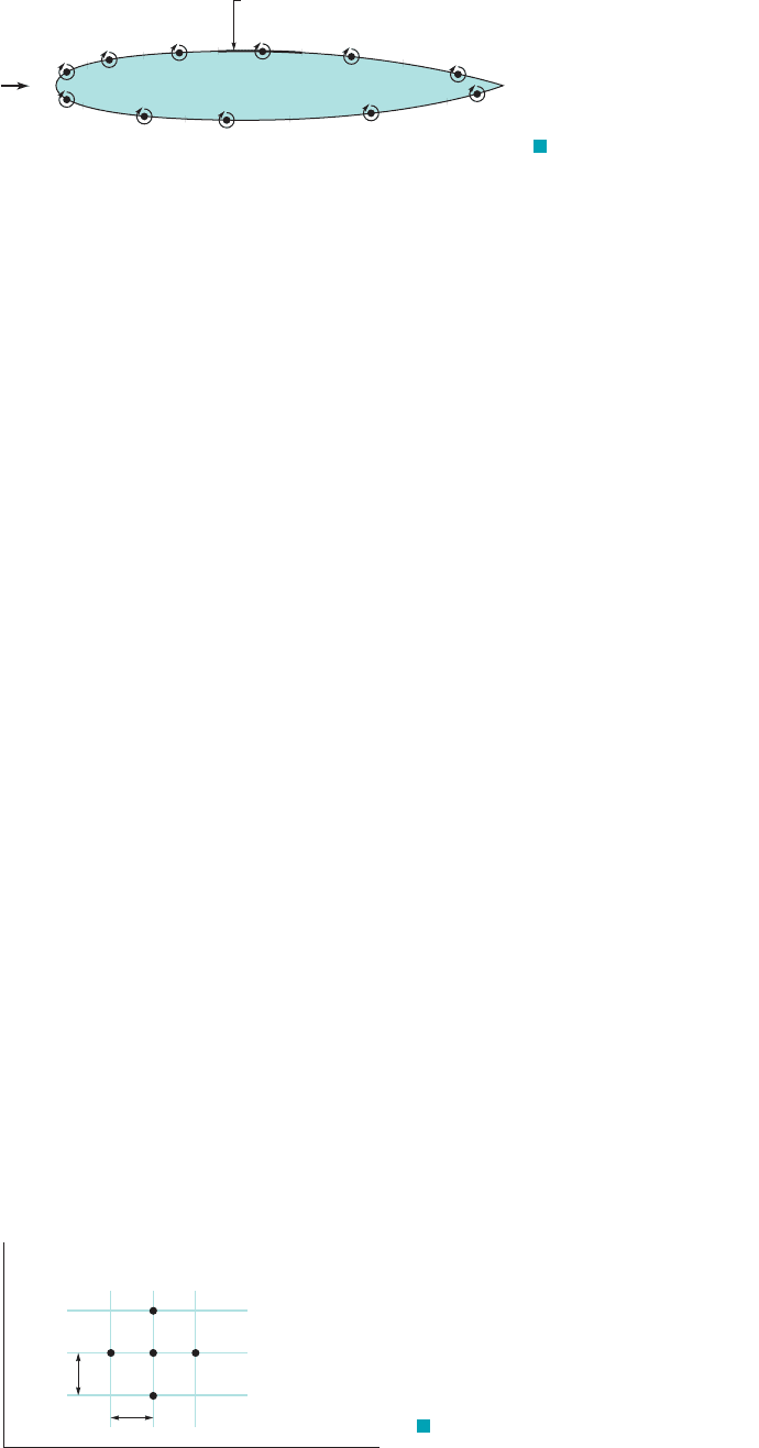
element method. Typical boundary elements and their associated singularities (vortices) for two-
dimensional flow past an airfoil are shown in Fig. A.1. Such use of the boundary element method
in aerodynamics is often termed the panel method in recognition of the fact that each element
plays the role of a panel on the airfoil surface (Ref. 4).
The finite difference method for computational fluid dynamics is perhaps the most eas-
ily understood and widely used of the three methods listed above. For this method the flow
field is dissected into a set of grid points and the continuous functions (velocity, pressure, etc.)
are approximated by discrete values of these functions calculated at the grid points. Deriva-
tives of the functions are approximated by using the differences between the function values
at local grid points divided by the grid spacing. The standard method for converting the par-
tial differential equations to algebraic equations is through the use of Taylor series expansions.
(See Ref. 5.) For example, assume a standard rectangular grid is applied to a flow domain as
shown in Fig. A.2.
This grid stencil shows five grid points in x–y space with the center point being labeled as
i, j. This index notation is used as subscripts on variables to signify location. For example,
is the u component of velocity at the first point to the right of the center point i, j. The grid spac-
ing in the i and j directions is given as and , respectively.¢y¢x
u
i⫹1, j
i – 1
i
th
panel
i
= strength of vortex on
i
th
panel
Γ
U
i
Γ
i+1
Γ
Γ
F I G U R E A.1 Panel
method for flow past an airfoil.
Δy
Δx
i – 1 ii + 1
j + 1
j
j
– 1
x
y
F I G U R E A.2 Standard rectangular
grid.
JWCL068_AppA_701-713.qxd 9/23/08 12:07 PM Page 702

A.3 Grids 703
To find an algebraic approximation to a first derivative term such as at the i, j grid
point, consider a Taylor series expansion written for u at as
(A.1)
Solving for the underlined term in the above equation results in the following:
(A.2)
where contains higher order terms proportional to , and so forth. Equation A.2
represents a forward difference equation to approximate the first derivative using values at
and i, j along with the grid spacing in the x direction. Obviously in solving for the term we
have ignored higher order terms such as the second and third derivatives present in Eq. A.1. This
process is termed truncation of the Taylor series expansion. The lowest order term that was trun-
cated included . Notice that the first derivative term contains . When solving for the first
derivative, all terms on the right-hand side were divided by . Therefore, the term signi-
fies that this equation has error of “order ,” which is due to the neglected terms in the Taylor
series and is called truncation error. Hence, the forward difference is termed first-order accurate.
Thus, we can transform a partial derivative into an algebraic expression involving values of
the variable at neighboring grid points. This method of using the Taylor series expansions to obtain
discrete algebraic equations is called the finite difference method. Similar procedures can be used
to develop approximations termed backward difference and central difference representations of
the first derivative. The central difference makes use of both the left and right points (i.e.,
) and is second-order accurate. In addition, finite difference equations can be
developed for the other spatial directions (i.e., ) as well as for second derivatives ,
which are also contained in the Navier–Stokes equations (see Ref. 5 for details).
Applying this method to all terms in the governing equations transfers the differential equa-
tions into a set of algebraic equations involving the physical variables at the grid points (i.e.,
etc.). This set of equations is then solved by appro-
priate numerical techniques. The larger the number of grid points used, the larger the number of
equations that must be solved.
A student of CFD should realize that the discretization of the continuum governing equa-
tions involves the use of algebraic equations that are an approximation to the original partial dif-
ferential equation. Along with this approximation comes some amount of error. This type of error
is termed truncation error because the Taylor series expansion used to represent a derivative is
“truncated” at some reasonable point and the higher order terms are ignored. The truncation errors
tend to zero as the grid is refined by making and smaller, so grid refinement is one method
of reducing this type of error. Another type of unavoidable numerical error is the so-called round-
off error. This type of error is due to the limit of the computer on the number of digits it can
retain in memory. Engineering students can run into round-off errors from their calculators if they
plug values into the equations at an early stage of the solution process. Fortunately, for most CFD
cases, if the algorithm is setup properly, round-off errors are usually negligible.
A.3 Grids
CFD computations using the finite difference method provide the flow field at discrete points in
the flow domain. The arrangement of these discrete points is termed the grid or the mesh. The
type of grid developed for a given problem can have a significant impact on the numerical sim-
ulation, including the accuracy of the solution. The grid must represent the geometry correctly
and accurately, since an error in this representation can have a significant effect on the solution.
The grid must also have sufficient grid resolution to capture the relevant flow physics, other-
wise they will be lost. This particular requirement is problem dependent. For example, if a flow
field has small-scale structures, the grid resolution must be sufficient to capture these structures. It
is usually necessary to increase the number of grid points (i.e., use a finer mesh) where large gra-
dients are to be expected, such as in the boundary layer near a solid surface. The same can also be
¢y¢x
u
i, j
, p
i, j
for i ⫽ 1, 2, 3, p and j ⫽ 1, 2, 3, p ,
10
2
u
Ⲑ
0x
2
20u
Ⲑ
0y
i ⫺ 1, j and i ⫹ 1, j
1¢x2
O1¢x2¢x
¢x1¢x2
2
0u
Ⲑ
0x
i ⫹ 1, j
¢x, 1¢x2
2
O1¢x2
a
0u
0x
b
i, j
⫽
u
i⫹1, j
⫺ u
i, j
¢x
⫹ O1¢x2
u
i⫹1, j
⫽ u
i, j
⫹ a
0u
0x
b
i, j
¢x
1!
⫹ a
0
2
u
0x
2
b
i, j
1¢x2
2
2!
⫹ a
0
3
u
0x
3
b
i, j
1¢x2
3
3!
⫹
p
i ⫹ 1
0u
Ⲑ
0x
JWCL068_AppA_701-713.qxd 9/23/08 12:07 PM Page 703
704 Appendix A ■ Computational Fluid Dynamics and FlowLab
said for the temporal resolution. The time step, , used for unsteady flows must be smaller than
the smallest time scale of the flow features being investigated.
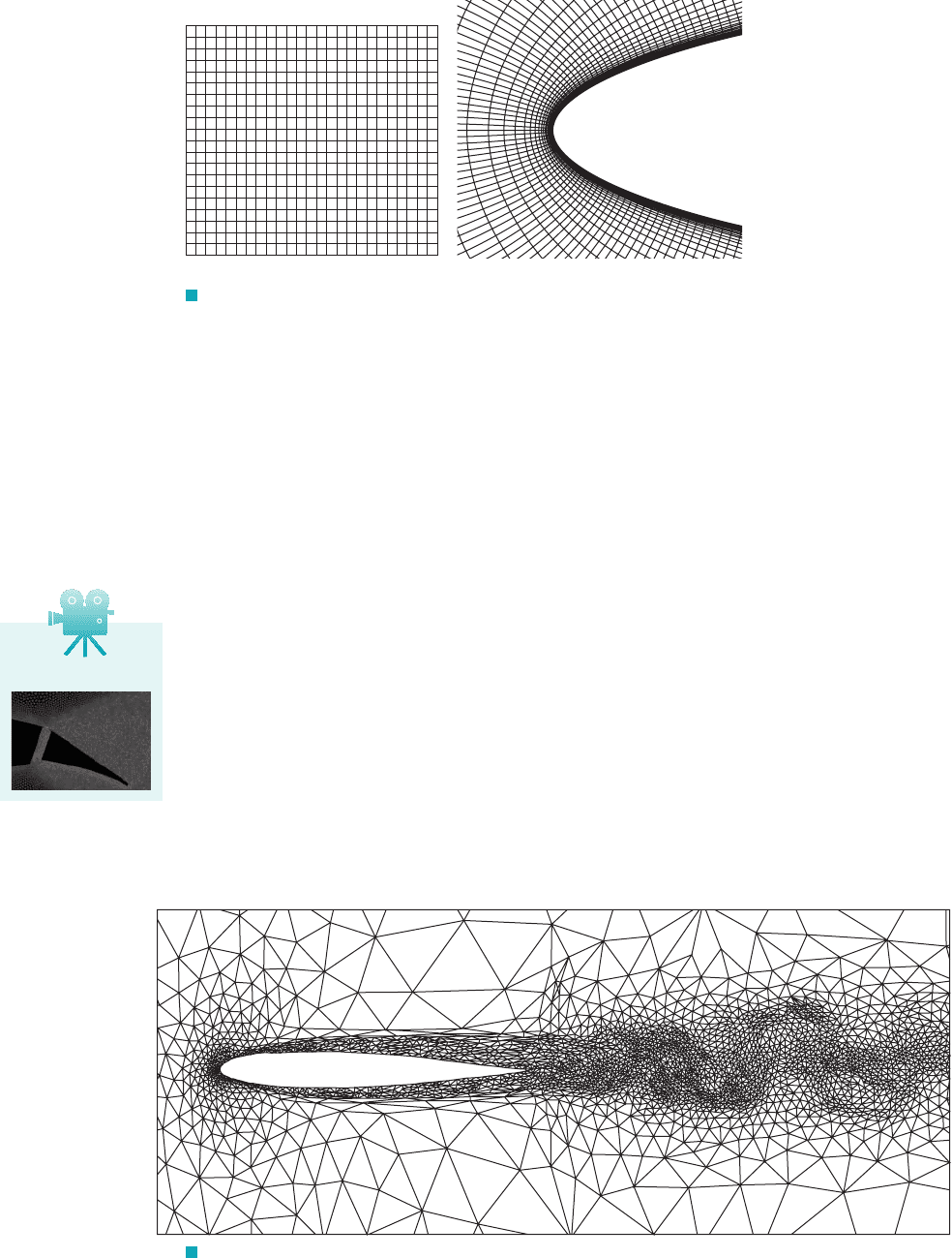
Generally, the types of grids fall into two categories: structured and unstructured, depending on
whether or not there exists a systematic pattern of connectivity of the grid points with their neighbors.
As the name implies, a structured grid has some type of regular, coherent structure to the mesh lay-
out that can be defined mathematically. The simplest structured grid is a uniform rectangular grid, as
shown in Fig. A.3a. However, structured grids are not restricted to rectangular geometries. Fig. A.3b
shows a structured grid wrapped around a parabolic surface. Notice that grid points are clustered near
the surface (i.e., grid spacing in normal direction increases as one moves away from the surface) to
help capture the steep flow gradients found in the boundary layer region. This type of variable grid
spacing is used wherever there is a need to increase grid resolution and is termed grid stretching.
For the unstructured grid, the grid cell arrangement is irregular and has no systematic pat-
tern. The grid cell geometry usually consists of various-sized triangles for two-dimensional prob-
lems and tetrahedrals for three-dimensional grids. An example of an unstructured grid is shown
in Fig. A.4. Unlike structured grids, for an unstructured grid each grid cell and the connection
information to neighboring cells is defined separately. This produces an increase in the computer
code complexity as well as a significant computer storage requirement. The advantage to an
unstructured grid is that it can be applied to complex geometries, where structured grids would
have severe difficulty. The finite difference method is restricted to structured grids whereas the
finite volume (or finite element) method can use either structured or unstructured grids.
Other grids include hybrid, moving, and adaptive grids. A grid that uses a combination of grid
elements (rectangles, triangles, etc.) is termed a hybrid grid. As the name implies, the moving grid
¢t
(a)(b)
F I G U R E A.3 Structured grids. (a) Rectangular grid.
(b) Grid around a parabolic surface.
VA.2 Dynamic grid
F I G U R E A.4 Anisotropic adaptive mesh for the calculation of viscous flow over a NACA
0012 airfoil at a Reynolds number of 10,000, Mach number of 0.755, and angle of attack of 1.5°. (From
CFD Laboratory, Concordia University, Montreal, Canada. Used by permission.)
JWCL068_AppA_701-713.qxd 9/23/08 12:07 PM Page 704

A.5 Basic Representative Examples 705
is helpful for flows involving a time-dependent geometry. If, for example, the problem involves
simulating the flow within a pumping heart or the flow around a flapping wing, a mesh that moves
with the geometry is desired. The nature of the adaptive grid lies in its ability to literally adapt
itself during the simulation. For this type of grid, while the CFD code is trying to reach a con-
verged solution, the grid will adapt itself to place additional grid resources in regions of high flow
gradients. Such a grid is particularly useful when a new problem arises and the user is not quite
sure where to refine the grid due to high flow gradients.
A.4 Boundary Conditions
The same governing equations, the Navier–Stokes equations (Eq. 6.127), are valid for all incom-
pressible Newtonian fluid flow problems. Thus, if the same equations are solved for all types of
problems, how is it possible to achieve different solutions for different types of flows involving
different flow geometries? The answer lies in the boundary conditions of the problem. The bound-
ary conditions are what allow the governing equations to differentiate between different flow fields
(for example, flow past an automobile and flow past a person running) and produce a solution
unique to the given flow geometry.
It is critical to specify the correct boundary conditions so that the CFD simulation is a well-
posed problem and is an accurate representation of the physical problem. Poorly defined boundary
conditions can ultimately affect the accuracy of the solution. One of the most common boundary
conditions used for simulation of viscous flow is the no-slip condition, as discussed in Section
1.6. Thus, for example, for two-dimensional external or internal flows, the x and y components
of velocity (u and v) are set to zero at the stationary wall to satisfy the no-slip condition. Other
boundary conditions that must be appropriately specified involve inlets, outlets, far-field, wall gra-
dients, etc. It is important to not only select the correct physical boundary condition for the prob-
lem, but also to correctly implement this boundary condition into the numerical simulation.
A.5 Basic Representative Examples
A very simple one-dimensional example of the finite difference technique is presented in the fol-
lowing example.
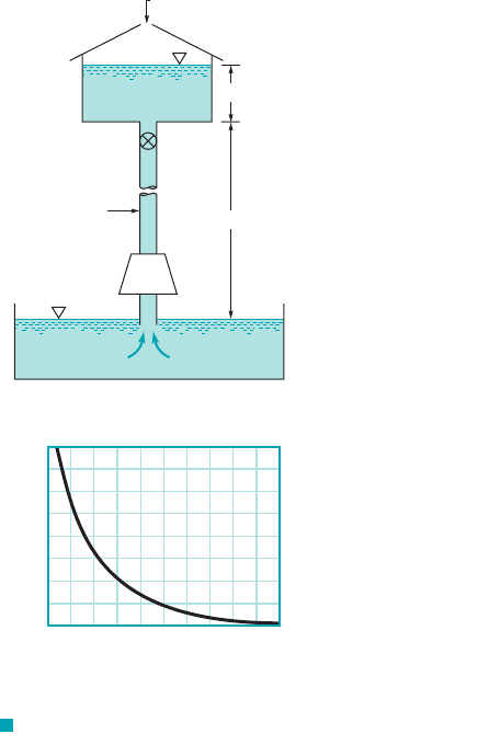
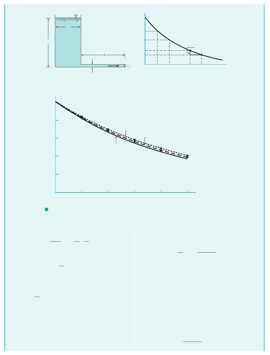
A viscous oil flows from a large, open tank and through a long,
small-diameter pipe as shown in Fig. EA.1a. At time the
fluid depth is H. Use a finite difference technique to determine the
t ⫽ 0
liquid depth as a function of time, Compare this result
with the exact solution of the governing equation.
h ⫽ h1t2.
S
OLUTION
Flow from a Tank
Conservation of mass requires that the flowrate from the tank,
is related to the rate of change of depth of oil in the
tank, by
where is the tank diameter. Thus,
or
(3)V ⫽⫺a
D
T
D
b
2
dh
dt
p
4
D
2
V ⫽⫺
p
4
D
2
T
dh
dt
D
T
Q ⫽⫺
p
4
D
2
T
dh
dt
dh
Ⲑ
dt,
Q ⫽ pD
2
V
Ⲑ
4,
E
XAMPLE A.1
Although this is an unsteady flow 1i.e., the deeper the oil, the faster
it flows from the tank2we assume that the flow is “quasisteady”
and apply steady flow equations as follows.
As shown by Eq. 6.152, the mean velocity, V, for steady lami-
nar flow in a round pipe of diameter D is given by
(1)
where is the pressure drop over the length For this prob-
lem the pressure at the bottom of the tank 1the inlet of the pipe2is
and that at the pipe exit is zero. Hence, and
Eq. 1 becomes
(2)V ⫽
D
2
gh
32m/
¢p ⫽ ghgh
/.¢p
V ⫽
D
2
¢p
32m/
JWCL068_AppA_701-713.qxd 9/23/08 12:07 PM Page 705
706 Appendix A ■ Computational Fluid Dynamics and FlowLab
By combining Eqs. 2 and 3 we obtain
or
where is a constant. For simplicity we assume
the conditions are such that Thus, we must solve
(4)
The exact solution to Eq. 4 is obtained by separating the vari-
ables and integrating to obtain
(5)
However, assume this solution was not known. The following fi-
nite difference technique can be used to obtain an approximate
solution.
h ⫽ He
⫺t
dh
dt
⫽⫺h
with
h ⫽ H at t ⫽ 0
C ⫽ 1.
C ⫽ gD
4
Ⲑ
32m/D
2
T
dh
dt
⫽⫺Ch
D
2
gh
32m/
⫽⫺a
D
T
D
b
2
dh
dt
As shown in Fig. EA.1b, we select discrete points 1nodes or
grid points2in time and approximate the time derivative of h by
the expression
(6)
where is the time step between the different node points on the
time axis and and are the approximate values of h at nodes i
and Equation 6 is called the backward-difference approxima-
tion to We are free to select whatever value of that we wish.
1Although we do not need to space the nodes at equal distances, it is
often convenient to do so.2Since the governing equation 1Eq. 42is an
ordinary differential equation, the “grid” for the finite difference
method is a one-dimensional grid as shown in Fig. EA.1brather than
a two-dimensional grid 1which occurs for partial differential equa-
tions2as shown in Fig. EA.2b, or a three-dimensional grid.
Thus, for each value of . . . we can approximate the
governing equation, Eq. 4, as
h
i
⫺ h
i⫺1
¢t
⫽⫺h
i
i ⫽ 2, 3, 4,
¢tdh
Ⲑ
dt.
i ⫺ 1.
h
i⫺1
h
i
¢t
dh
dt
`
t⫽t
i
⬇
h
i
⫺ h
i⫺1
¢t
h
D
T
D
V
0.0 0.2 0.4 0.6 0.8 1.0
t
0.2H
0.4H
0.6H
0.8H
H
0 Δt 2Δt
i = 1 2 3 i – 1 i
(b)(a)
(c)
Δt
t
h
h
H
h
2
h
3
h
i –1
h
i
Exact: h = He
-t
t = 0.2
h
i
– h
i –1
Δ
t = 0.1
Δ
0
F I G U R E EA.1
JWCL068_AppA_701-713.qxd 9/23/08 12:07 PM Page 706