Munson B.R. Fundamentals of Fluid Mechanics
Подождите немного. Документ загружается.

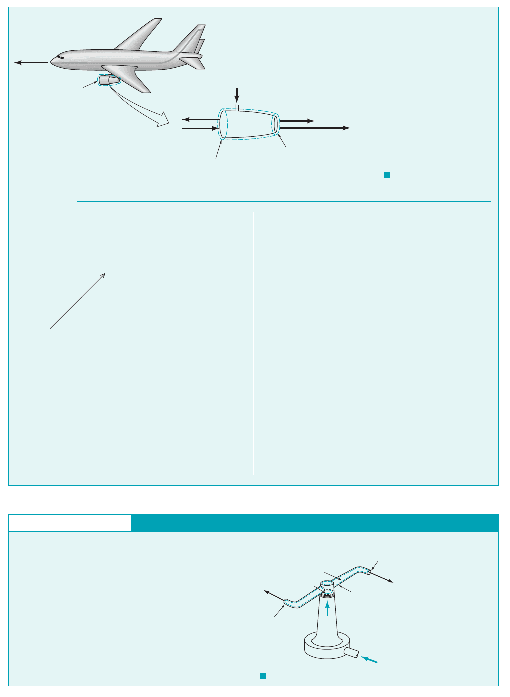
5.1 Conservation of Mass—The Continuity Equation 197
The control volume, which moves with the airplane 1see Fig.
E5.6b2, surrounds the engine and its contents and includes all flu-
ids involved at an instant. The application of Eq. 5.16 to these
contents of the control volume yields
0 1flow relative to moving control
volume is considered steady on a
time-average basis2
(1)
Assuming one-dimensional flow, we evaluate the surface integral
in Eq. 1 and get
or
(2)
We consider the intake velocity, , relative to the moving con-
trol volume, as being equal in magnitude to the speed of the air-
plane, The exhaust velocity, also needs to be
measured relative to the moving control volume. Since a fixed
W
2
,
971 km
Ⲑ
hr.
W
1
m
#
fuel
in
⫽ r
2
A
2
W
2
⫺ r
1
A
1
W
1
⫺m
#
fuel
in
⫺ r
1
A
1
W
1
⫹ r
2
A
2
W
2
⫽ 0
0
0t
冮
cv
r dV⫺⫹
冮
cs
rW ⴢ nˆ dA ⫽ 0
observer noted that the exhaust gases were moving away from the
engine at a speed of the speed of the exhaust gases
relative to the moving control volume, is determined as fol-
lows by using Eq. 5.14
or
and is shown in Fig. E5.6b.
From Eq. 2,
(Ans)
COMMENT Note that the fuel flowrate was obtained as the
difference of two large, nearly equal numbers. Precise values of
and are needed to obtain a modestly accurate value of
m
#
fuel
in
.
W
1
W
2
m
#
fuel
in
⫽ 9100 kg
Ⲑ
hr
⫽ 1580,800 ⫺ 571,7002 kg
Ⲑ
hr
⫺ 10.736 kg
Ⲑ
m
3
210.80 m
2
21971 km
Ⲑ
hr211000 m
Ⲑ
km2
m
#
fuel
in
⫽ 10.515 kg
Ⲑ
m
3
2
10.558 m
2
2
12021 km
Ⲑ
hr2 11000 m
Ⲑ
km2
⫽ 2021 km
Ⲑ
hr
W
2
⫽ V
2
⫺ V
plane
⫽ 1050 km
Ⲑ
hr ⫺ 1⫺971 km
Ⲑ
hr2
V
2
⫽ W
2
⫹ V
plane
W
2
,
1050 km
Ⲑ
hr,
Control volume
V
plane
=
971 km/hr
V
plane
=
971 km/hr
W
1
=
971 km/hr
W
2
= 1050 + 971 =
2021 km/hr
V
2
= 1050 km/hr
m
•
fuel in
Section (1)
Section (2)
(a)
(
b)
F I G U R E E5.6
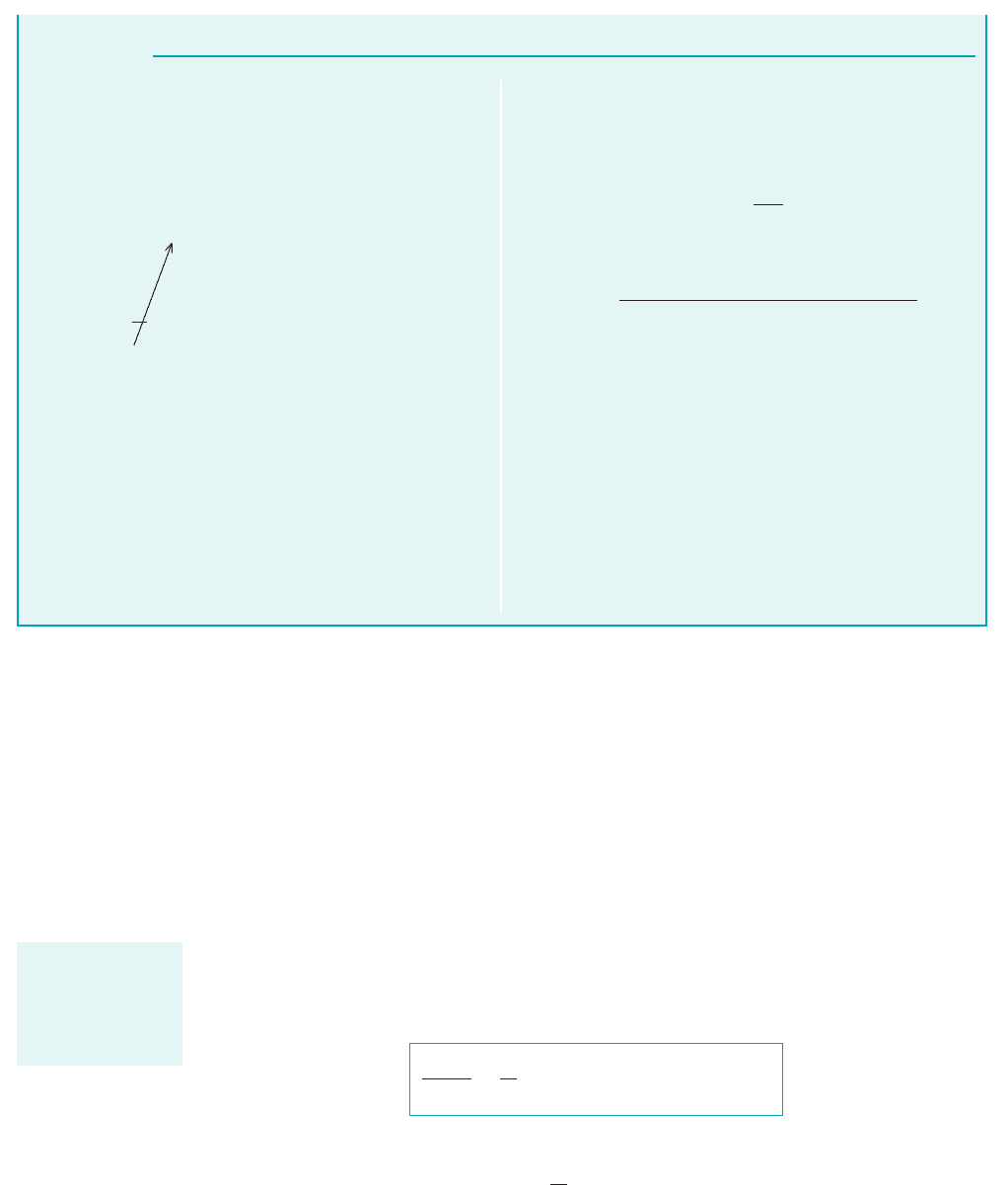
GIVEN Water enters a rotating lawn sprinkler through its base
at the steady rate of 1000 ml/s as sketched in Fig. E5.7. The exit
area of each of the two nozzles is 30 mm
2
.
FIND Determine the average speed of the water leaving the
nozzle, relative to the nozzle, if
(a) the rotary sprinkler head is stationary,
(b) the sprinkler head rotates at 600 rpm, and
(c) the sprinkler head accelerates from 0 to 600 rpm.
F I G U R E E5.7
Conservation of Mass—Relative Velocity
Control volume
Section (3)
Sprinkler head
W
2
Q
Q = 1000 ml/s
Section (1)
A
2
= 30 mm
2
Section (2)
E
XAMPLE 5.7
S
OLUTION
JWCL068_ch05_187-262.qxd 9/23/08 9:54 AM Page 197
When a moving, nondeforming control volume is used, the dot product sign convention
used earlier for fixed, nondeforming control volume applications is still valid. Also, if the flow
within the moving control volume is steady, or steady on a time-average basis, the time rate of
change of the mass of the contents of the control volume is zero. Velocities seen from the con-
trol volume reference frame 1relative velocities2must be used in the continuity equation. Rela-
tive and absolute velocities are related by a vector equation 1Eq. 5.142, which also involves the
control volume velocity.
5.1.4 Deforming Control Volume
Occasionally, a deforming control volume can simplify the solution of a problem. A deforming
control volume involves changing volume size and control surface movement. Thus, the Reynolds
transport theorem for a moving control volume can be used for this case, and Eqs. 4.23 and 5.1
lead to
(5.17)
The time rate of change term in Eq. 5.17,
is usually nonzero and must be carefully evaluated because the extent of the control volume varies
with time. The mass flowrate term in Eq. 5.17,
冮
cs
rW ⴢ nˆ dA
0
0t
冮
cv
r dV⫺
DM
sys
Dt
⫽
0
0t
冮
cv
r dV⫺⫹
冮
cs
rW ⴢ nˆ dA ⫽ 0
198 Chapter 5 ■ Finite Control Volume Analysis
S
OLUTION
Hence, for incompressible flow with
1
⫽
2
⫽
3
, Eq. 2 becomes
With Q ⫽ A
1
W
1
, A
2
⫽ A
3
, and W
2
⫽ W
3
it follows that
or
(Ans)
(b), (c) The value of W
2
is independent of the speed of rotation
of the sprinkler head and represents the average velocity of the
water exiting from each nozzle with respect to the nozzle for
cases (a), (b), and (c).
COMMENT The velocity of water discharging from each noz-
zle, when viewed from a stationary reference (i.e., V
2
), will vary as
the rotation speed of the sprinkler head varies since from Eq. 5.14,
where U ⫽ R is the speed of the nozzle and and R are the an-
gular velocity and radius of the sprinkler head, respectively.
V
2
⫽ W
2
⫺ U
⫽ 16.7 m/s
W
2
⫽
11000 ml/s210.001 m
3
/liter2110
6
mm
2
/m
2
2
11000 ml/liter2122130 mm
2
2
W
2
⫽
Q
2 A
2
A
2
W
2
⫹ A
3
W
3
⫺ A
1
W
1
⫽ 0
(a) We specify a control volume that contains the water in the
rotary sprinkler head at any instant. This control volume is non-
deforming, but it moves (rotates) with the sprinkler head.
The application of Eq. 5.16 to the contents of this control volume
for situation (a), (b), or (c) of the problem results in the same ex-
pression, namely
0 flow is steady or the
control volume is filled with
an incompressible fluid
or
(1)
The time rate of change of the mass of water in the control vol-
ume is zero because the flow is steady and the control volume is
filled with water.
Because there is only one inflow [at the base of the rotating
arm, section (1)] and two outflows [the two nozzles at the tips of
the arm, sections (2) and (3), each have the same area and fluid
velocity], Eq. 1 becomes
(2)
2
A
2
W
2
⫹
3
A
3
W
3
⫺
1
A
1
W
1
⫽ 0
gr
out
A
out
W
out
⫺ gr
in
A
in
W
in
⫽ 0
0
0t
冮
cv
r d V⫺⫹
冮
cs
rW ⴢ
ˆ
n dA ⫽ 0
Care is needed to
ensure that absolute
and relative veloci-
ties are used cor-
rectly.
JWCL068_ch05_187-262.qxd 9/23/08 9:54 AM Page 198
must be determined with the relative velocity, W, the velocity referenced to the control surface.
Since the control volume is deforming, the control surface velocity is not necessarily uniform and
identical to the control volume velocity, as was true for moving, nondeforming control vol-
umes. For the deforming control volume,
(5.18)
where is the velocity of the control surface as seen by a fixed observer. The relative velocity, W,
must be ascertained with care wherever fluid crosses the control surface. Two example problems that
illustrate the use of the continuity equation for a deforming control volume, Eq. 5.17, follow.
V
cs
V ⫽ W ⫹ V
cs
V
cv
,
5.1 Conservation of Mass—The Continuity Equation 199
The velocity of the
surface of a de-
forming control
volume is not the
same at all points
on the surface.
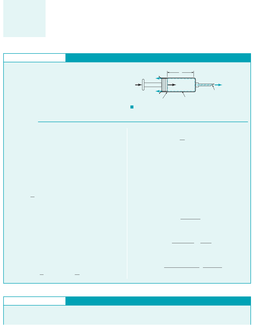
GIVEN A syringe 1Fig. E5.82is used to inoculate a cow. The
plunger has a face area of The liquid in the syringe is
to be injected steadily at a rate of The leakage rate
past the plunger is 0.10 times the volume flowrate out of the
needle.
FIND With what speed should the plunger be advanced?
300 cm
3
Ⲑ
min.
500 mm
2
.
S
OLUTION
F I G U R E E5.8
Conservation of Mass—Deforming Control Volume
Note that
(5)
where is the speed of the plunger sought in the problem state-
ment. Combining Eqs. 2, 4, and 5 we obtain
(6)
However, from Eq. 5.6, we see that
(7)
and Eq. 6 becomes
(8)
Solving Eq. 8 for yields
(9)
Since Eq. 9 becomes
and
(Ans)
⫽ 660 mm
Ⲑ
min
V
p
⫽
11.121300 cm
3
Ⲑ
min2
1500 mm
2
2
a
1000 mm
3
cm
3
b
V
p
⫽
Q
2
⫹ 0.1Q
2
A
1
⫽
1.1Q
2
A
1
Q
leak
⫽ 0.1Q
2
,
V
p
⫽
Q
2
⫹ Q
leak
A
1
V
p
⫺rA
1
V
p
⫹ rQ
2
⫹ rQ
leak
⫽ 0
m
#
2
⫽ rQ
2
⫺rA
1
V
p
⫹ m
#
2
⫹ rQ
leak
⫽ 0
V
p
⫺
0/
0t
⫽ V
p
Plunger
motion
Section (1)
Section (2)
Control volume
Q
leak
=
0.1
Q
2
Q
2
=
300 cm
3
/min
V
p
A
p
=
500 mm
2
ᐉ
E
XAMPLE 5.8
The control volume selected for solving this problem is the de-
forming one illustrated in Fig. E5.8. Section 112of the control sur-
face moves with the plunger. The surface area of section 112, is
considered equal to the circular area of the face of the plunger, ,
although this is not strictly true, since leakage occurs. The differ-
ence is small, however. Thus,
(1)
Liquid also leaves the needle through section 122, which involves
fixed area The application of Eq. 5.17 to the contents of this
control volume gives
(2)
Even though and the flow through section area are
steady, the time rate of change of the mass of liquid in the
shrinking control volume is not zero because the control volume
is getting smaller. To evaluate the first term of Eq. 2, we note
that
(3)
where is the changing length of the control volume 1see Fig.
E5.82and is the volume of the needle. From Eq. 3, we
obtain
(4)
0
0t
冮
cv
r dV⫺⫽rA
1
0/
0t
V⫺
needle
/
冮
cv
r dV⫺⫽r1/A
1
⫹ V⫺
needle
2
A
2
Q
leak
0
0t
冮
cv
r dV⫺⫹m
#
2
⫹ rQ
leak
⫽ 0
A
2
.
A
1
⫽ A
p
A
p
A
1
,
GIVEN Consider Example 5.5.
FIND Solve the problem of Example 5.5 using a deforming con-
trol volume that includes only the water accumulating in the bathtub.
Conservation of Mass—Deforming Control Volume
E
XAMPLE 5.9
JWCL068_ch05_187-262.qxd 9/23/08 9:55 AM Page 199

The conservation of mass principle is easily applied to the contents of a control volume. The
appropriate selection of a specific kind of control volume 1for example, fixed and nondeforming,
moving and nondeforming, or deforming2can make the solution of a particular problem less com-
plicated. In general, where fluid flows through the control surface, it is advisable to make the con-
trol surface perpendicular to the flow. In the sections ahead we learn that the conservation of mass
principle is primarily used in combination with other important laws to solve problems.
200 Chapter 5 ■ Finite Control Volume Analysis
S
OLUTION
For this deforming control volume, Eq. 5.17 leads to
(1)
The first term of Eq. 1 can be evaluated as
(2)
The second term of Eq. 1 can be evaluated as
(3)
冮
cs
r W ⴢ nˆ dA r aV
j
0h
0t
b A
j
r 110 ft
2
2
0h
0t
0
0t
冮
water
volume
r dV
0
0t
3rh12 ft215 ft24
0
0t
冮
water
volume
r dV
冮
cs
rW ⴢ nˆ dA 0
where and are the cross-sectional area and velocity of the
water flowing from the faucet into the tube. Thus, from Eqs. 1, 2,
and 3 we obtain
or for
(Ans)
COMMENT Note that these results using a deforming con-
trol volume are the same as that obtained in Example 5.5 with a
fixed control volume.
0h
0t
91gal
min2112 in.
ft2
17.48 gal
ft
3
2110 ft
2
2
1.44 in.
min
A
j
10 ft
2
0h
0t
V
j
A
j
110 ft
2
A
j
2
Q
water
110 ft
2
A
j
2
V
j
A
j
5.2.1 Derivation of the Linear Momentum Equation
Newton’s second law of motion for a system is
Since momentum is mass times velocity, the momentum of a small particle of mass is
Thus, the momentum of the entire system is and Newton’s law becomes
(5.19)
Any reference or coordinate system for which this statement is true is called inertial. A fixed coor-
dinate system is inertial. A coordinate system that moves in a straight line with constant velocity
and is thus without acceleration is also inertial. We proceed to develop the control volume formula
for this important law. When a control volume is coincident with a system at an instant of time,
the forces acting on the system and the forces acting on the contents of the coincident control vol-
ume 1see Fig. 5.22are instantaneously identical, that is,
(5.20)
Furthermore, for a system and the contents of a coincident control volume that is fixed and non-
deforming, the Reynolds transport theorem [Eq. 4.19 with b set equal to the velocity (i.e., momen-
tum per unit mass), and being the system momentum] allows us to conclude that
(5.21)
D
Dt
冮
sys
Vr dV
0
0t
冮
cv
Vr dV
冮
cs
VrV
#
nˆ dA
B
sys
a
F
sys
a
F
contents of the
coincident control volume
D
Dt
冮
sys
Vr dV
a
F
sys
兰
sys
VrdVVrdV.
rdV
time rate of change of the
linear momentum of the system
sum of external forces
acting on the system
5.2 Newton’s Second Law—The Linear Momentum
and Moment-of-Momentum Equations
V5.4 Smokestack
plume momentum
Forces acting on a
flowing fluid can
change its velocity
magnitude and/or
direction.
JWCL068_ch05_187-262.qxd 9/23/08 9:55 AM Page 200
or
Equation 5.21 states that the time rate of change of system linear momentum is expressed
as the sum of the two control volume quantities: the time rate of change of the linear momentum
of the contents of the control volume, and the net rate of linear momentum flow through the con-
trol surface. As particles of mass move into or out of a control volume through the control sur-
face, they carry linear momentum in or out. Thus, linear momentum flow should seem no more
unusual than mass flow.
For a control volume that is fixed 1and thus inertial2and nondeforming, Eqs. 5.19, 5.20, and 5.21
provide an appropriate mathematical statement of Newton’s second law of motion as
(5.22)
We call Eq. 5.22 the linear momentum equation.
In our application of the linear momentum equation, we initially confine ourselves to fixed,
nondeforming control volumes for simplicity. Subsequently, we discuss the use of a moving but
inertial, nondeforming control volume. We do not consider deforming control volumes and accel-
erating 1noninertial2control volumes. If a control volume is noninertial, the acceleration compo-
nents involved 1for example, translation acceleration, Coriolis acceleration, and centrifugal accel-
eration2require consideration.
The forces involved in Eq. 5.22 are body and surface forces that act on what is contained in
the control volume as shown in the sketch in the margin. The only body force we consider in this
chapter is the one associated with the action of gravity. We experience this body force as weight, w.
The surface forces are basically exerted on the contents of the control volume by material just out-
side the control volume in contact with material just inside the control volume. For example, a wall
in contact with fluid can exert a reaction surface force on the fluid it bounds. Similarly, fluid just
outside the control volume can push on fluid just inside the control volume at a common interface,
usually an opening in the control surface through which fluid flow occurs. An immersed object
can resist fluid motion with surface forces.
The linear momentum terms in the momentum equation deserve careful explanation. We clar-
ify their physical significance in the following sections.
5.2.2 Application of the Linear Momentum Equation
The linear momentum equation for an inertial control volume is a vector equation 1Eq. 5.222. In
engineering applications, components of this vector equation resolved along orthogonal coordi-
nates, for example, x, y, and z 1rectangular coordinate system2or r, and x 1cylindrical coordinate
system2, will normally be used. A simple example involving steady, incompressible flow is con-
sidered first.
u,
0
0t
冮
cv
Vr dV⫺⫹
冮
cs
VrV ⴢ nˆ dA ⫽
a
F
contents of the
control volume
time rate of change
of the linear
momentum of the
system
⫽
time rate of change
of the linear
momentum of the
contents of the
control volume
⫹
net rate of flow
of linear momentum
through the
control surface
5.2 Newton’s Second Law—The Linear Momentum and Moment-of-Momentum Equations 201
F
D
F
E
F
F
F
G
F
C
F
B
F
A
Coincident
control volume
System
F I G U R E 5.2 External forces acting on system and
coincident control volume.
V5.6 Force due to a
water jet
Flow out
Flow in
Control volume
F
fluid in
F
fluid out
F
wall
ᐃ
V5.5 Marine
propulsion
JWCL068_ch05_187-262.qxd 9/23/08 9:55 AM Page 201
202 Chapter 5 ■ Finite Control Volume Analysis
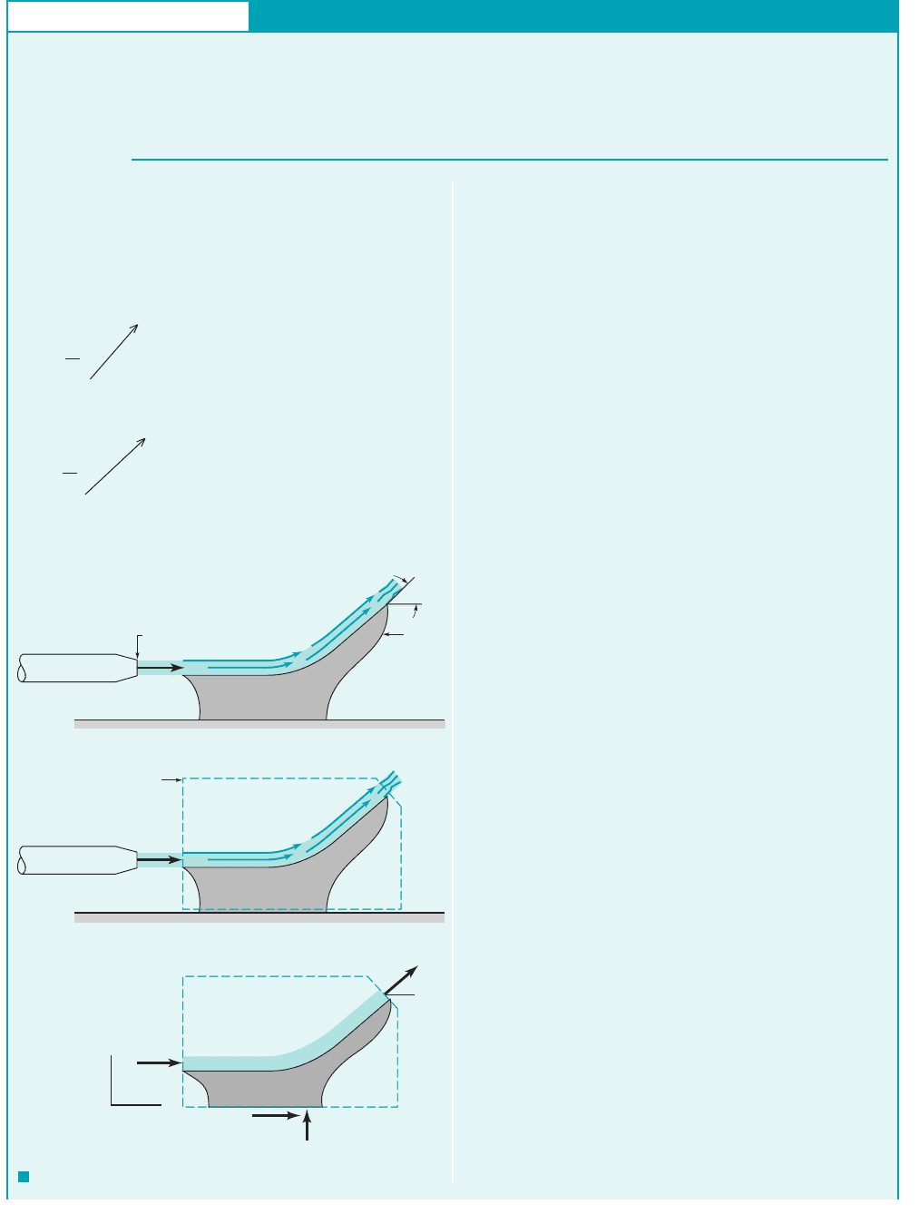
GIVEN As shown in Fig. E5.10a, a horizontal jet of water ex-
its a nozzle with a uniform speed of V
1
⫽ 10 ft/s, strikes a vane,
and is turned through an angle .
S
OLUTION
F I G U R E E5.10
Linear Momentum—Change in Flow Direction
and
(2)
where V ⫽ ui
ˆ
⫹ wk
ˆ
, and ⌺F
x
and ⌺F
z
are the net x and z compo-
nents of force acting on the contents of the control volume. De-
pending on the particular flow situation being considered and the
coordinate system chosen, the x and z components of velocity, u
and w, can be positive, negative, or zero. In this example the flow is
in the positive directions at both the inlet and the outlet.
The water enters and leaves the control volume as a free jet at
atmospheric pressure. Hence, there is atmospheric pressure sur-
rounding the entire control volume, and the net pressure force on
the control volume surface is zero. If we neglect the weight of the
water and vane, the only forces applied to the control volume con-
tents are the horizontal and vertical components of the anchoring
force, F
Ax
and F
Az
, respectively.
With negligible gravity and viscous effects, and since p
1
⫽ p
2
,
the speed of the fluid remains constant so that V
1
⫽ V
2
⫽ 10 ft/s
(see the Bernoulli equation, Eq. 3.7). Hence, at section (1),
u
1
⫽ V
1
, w
1
⫽ 0, and at section (2), u
2
⫽ V
1
cos , w
2
⫽ V
1
sin .
By using this information, Eqs. 1 and 2 can be written as
(3)
and
(4)
Equations 3 and 4 can be simplified by using conservation of
mass, which states that for this incompressible flow A
1
V
1
⫽
A
2
V
2
, or A
1
⫽ A
2
since V
1
⫽ V
2
. Thus
(5)
and
(6)
With the given data we obtain
(Ans)
and
(Ans)
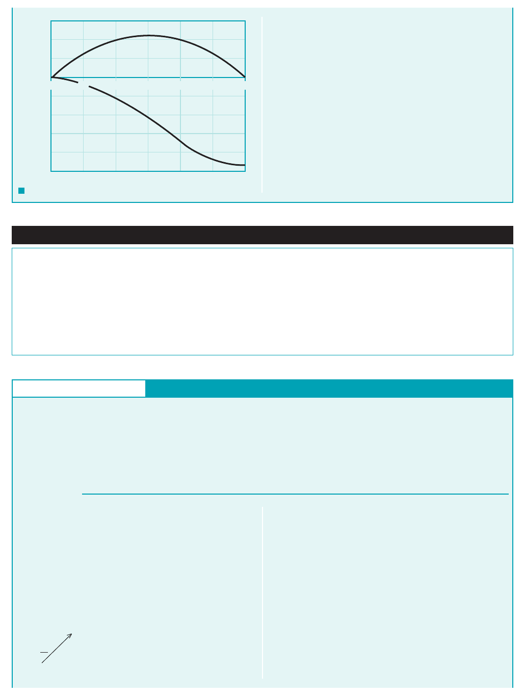
COMMENTS The values of F
Ax
and F
Az
as a function of are
shown in Fig. E5.10d. Note that if ⫽ 0 (i.e., the vane does not
turn the water), the anchoring force is zero. The inviscid fluid
merely slides along the vane without putting any force on it. If
⫽ 90°, then F
Ax
⫽⫺11.64 lb and F
Az
⫽ 11.64 lb. It is necessary
to push on the vane (and, hence, for the vane to push on the water)
⫽ 11.64 sin u lb
F
Az
⫽ 11.94 slugs
/
ft
3
210.06 ft
2
2110 ft
/
s2
2
sin u
⫽⫺11.6411 ⫺ cos u2 lb
⫽⫺11.6411 ⫺ cos u2 slugs ⴢ ft
/
s
2
F
Ax
⫽⫺11.94 slugs
/
ft
3
210.06 ft
2
2110 ft
/
s2
2
11 ⫺ cos u2
F
Az
⫽ A
1
V
2
1
sin
F
Ax
⫽⫺A
1
V
2
1
⫹ A
1
V
2
1
cos ⫽⫺A
1
V
2
1
11 ⫺ cos 2
V
1
sin A
2
V
1
⫺ 0 A
1
V
1
⫽ F
Az
V
1
cos A
2
V
1
⫺ V
1
A
1
V
1
⫽ F
Ax
w
2
A
2
V
2
⫺ w
1
A
1
V
1
⫽ gF
z
Nozzle
A
1
= 0.06 ft
2
Vane
V
1
(a)
θ
Nozzle
V
1
(b)
Control
volume
(c)
z
x
(2)
F
Ax
F
Az
V
1
V
2
θ
(1)
E
XAMPLE 5.10
We select a control volume that includes the vane and a portion of
the water (see Figs. E5.10b, c) and apply the linear momentum
equation to this fixed control volume. The only portions of the
control surface across which fluid flows are section (1) (the en-
trance) and section (2) (the exit). Hence, the x and z components
of Eq. 5.22 become
0 1flow is steady2
and
0 1flow is steady2
or
(1)u
2
A
2
V
2
⫺ u
1
A
1
V
1
⫽ gF
x
0
0t
冮
cv
w r dV⫺⫹
冮
cs
w r V ⴢ nˆ dA ⫽
a
F
z
0
0t
冮
cv
u r dV⫺⫹
冮
cs
u r V ⴢ nˆ dA ⫽
a
F
x
FIND Determine the anchoring force needed to hold the vane
stationary if gravity and viscous effects are negligible.
JWCL068_ch05_187-262.qxd 9/30/08 8:19 AM Page 202
5.2 Newton’s Second Law—The Linear Momentum and Moment-of-Momentum Equations 203
to the left (F
Ax
is negative) and up in order to change the direction
of flow of the water from horizontal to vertical. This momentum
change requires a force. If 180°, the water jet is turned back
on itself. This requires no vertical force (F
Az
0), but the hori-
zontal force (F
Ax
23.3 lb) is two times that required if
90°. This horizontal fluid momentum change requires a hor-
izontal force only.
Note that the anchoring force (Eqs. 5, 6) can be written in
terms of the mass flowrate, as
and
In this example exerting a force on a fluid flow resulted in a
change in its direction only (i.e., change in its linear momentum).
F
Az
m
#
V
1
sin
F
Ax
m
#
V
1
11 cos 2
m
#
A
1
V
1
,
F I G U R E E5.10
d
–25
–20
–15
–10
–5
0
5
10
15
F
Ax
or F
Az
,
lb
30 60 90 120 150 180
θ
, deg
F
Ax
F
Az
0
Fluids in the News
Where the plume goes Commercial airliners have wheel brakes
very similar to those on highway vehicles. In fact, antilock brakes
now found on most new cars were first developed for use on air-
planes. However, when landing, the major braking force comes
from the engine rather than the wheel brakes. Upon touchdown, a
piece of engine cowling translates aft and blocker doors drop
down, directing the engine airflow into a honeycomb structure
called a cascade. The cascade reverses the direction of the high-
speed engine exhausts by nearly so that it flows forward. As180°
predicted by the momentum equation, the air passing through the
engine produces a substantial braking force—the reverse thrust.
Designers must know the flow pattern of the exhaust plumes to
eliminate potential problems. For example, the plumes of hot ex-
haust must be kept away from parts of the aircraft where repeated
heating and cooling could cause premature fatigue. Also, the
plumes must not re-enter the engine inlet, or blow debris from the
runway in front of the engine, or envelop the vertical tail. (See
Problem 5.67.)
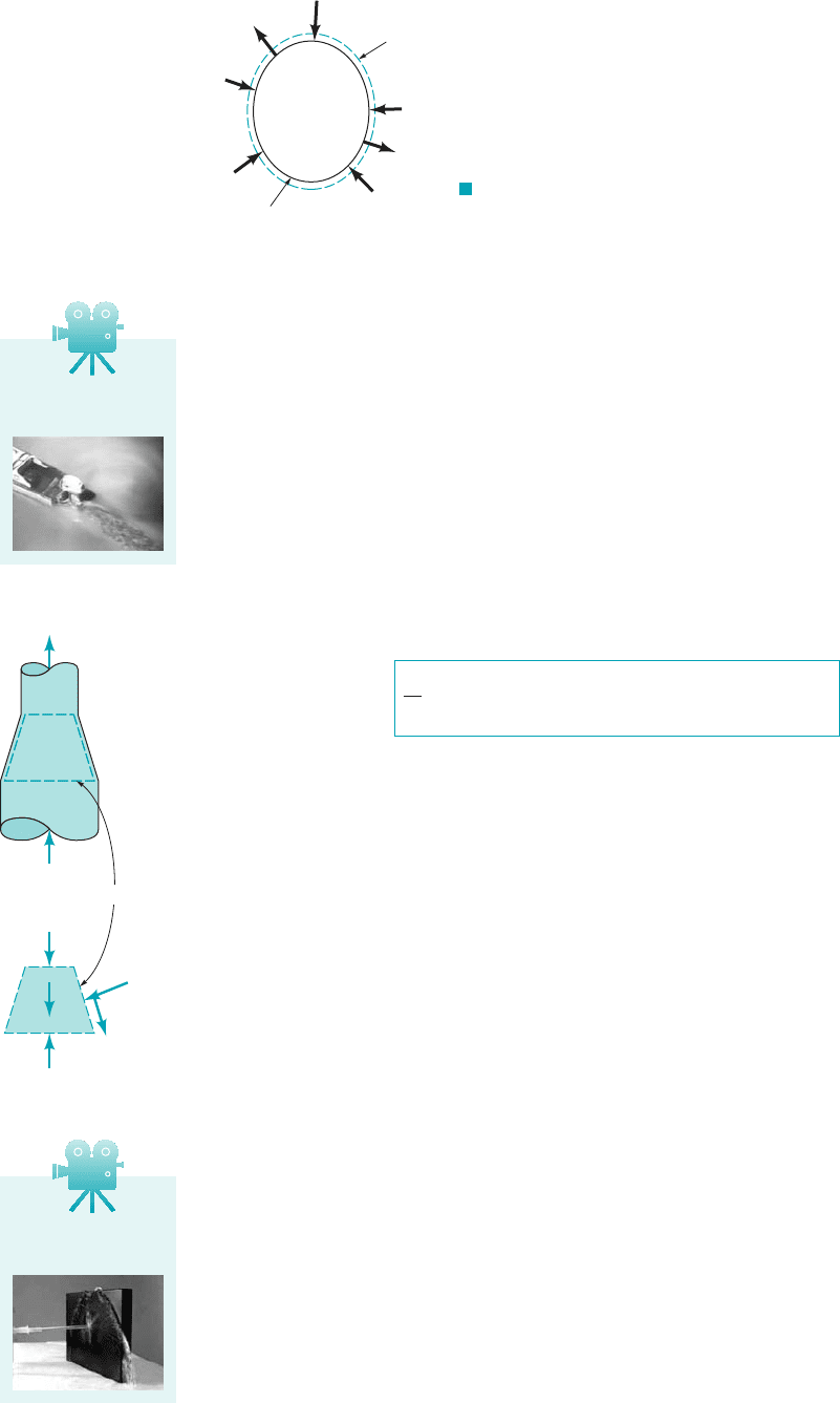
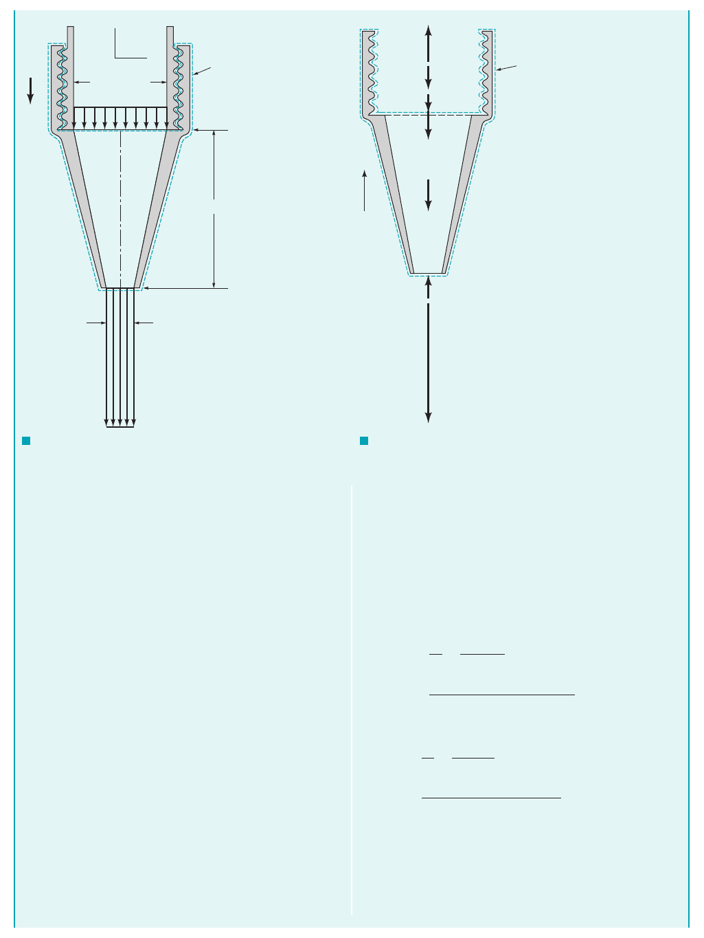
GIVEN As shown in Fig. E5.11a, water flows through a noz-
zle attached to the end of a laboratory sink faucet with a flowrate
of 0.6 liters/s. The nozzle inlet and exit diameters are 16 and 5
mm, respectively, and the nozzle axis is vertical. The mass of the
nozzle is 0.1 kg. The pressure at section (1) is 464 kPa.
S
OLUTION
Linear Momentum—Weight, Pressure, and Change in Speed
where w is the z direction component of fluid velocity, and the
various parameters are identified in the figure.
Note that the positive direction is considered “up” for the
forces. We will use this same sign convention for the fluid veloc-
ity, w, in Eq. 1. In Eq. 1, the dot product, is for flow
out of the control volume and for flow into the control vol-
ume. For this particular example
(2)
with the used for flow out of the control volume and
used for flow in. To evaluate the control surface integral in Eq. 1,
we need to assume a distribution for fluid velocity, w, and fluid
density, For simplicity, we assume that w is uniformly distrib-
uted or constant, with magnitudes of and over cross-
sectional areas and Also, this flow is incompressible so the
A
2
.A
1
w
2
w
1
r.
“”“”
V ⴢ nˆ dA 0w0 dA
“”
“”V ⴢ nˆ,
E
XAMPLE 5.11
The anchoring force sought is the reaction force between the
faucet and nozzle threads. To evaluate this force we select a con-
trol volume that includes the entire nozzle and the water contained
in the nozzle at an instant, as is indicated in Figs. E5.11a and
E5.11b. All of the vertical forces acting on the contents of this con-
trol volume are identified in Fig. E5.11b. The action of atmos-
pheric pressure cancels out in every direction and is not shown.
Gage pressure forces do not cancel out in the vertical direction and
are shown. Application of the vertical or z direction component of
Eq. 5.22 to the contents of this control volume leads to
0 1flow is steady2
(1) w
w
p
2
A
2
0
0t
冮
cv
wr dV
冮
cs
wrV ⴢ nˆ dA F
A
w
n
p
1
A
1
FIND Determine the anchoring force required to hold the noz-
zle in place.
JWCL068_ch05_187-262.qxd 9/23/08 9:55 AM Page 203
204 Chapter 5 ■ Finite Control Volume Analysis
fluid density, is constant throughout. Proceeding further we ob-
tain for Eq. 1
(3)
where is the mass flowrate.
Note that and are used because both of these veloc-
ities are “down.” Also, is used because it is associated with
flow into the control volume. Similarly, is used because it is
associated with flow out of the control volume. Solving Eq. 3 for
the anchoring force, we obtain
(4)
From the conservation of mass equation, Eq. 5.12, we obtain
(5)
which when combined with Eq. 4 gives
(6)
It is instructive to note how the anchoring force is affected
by the different actions involved. As expected, the nozzle
weight, the water weight, and gage pressure force at
section 112, all increase the anchoring force, while the
gage pressure force at section 122, acts to decrease the
anchoring force. The change in the vertical momentum
flowrate, will, in this instance, decrease the an-
choring force because this change is negative
1w
2
7 w
1
2.
m
#
1w
1
⫺ w
2
2,
p
2
A
2
,
p
1
A
1
,
w
w
,w
n
,
F
A
⫽ m
#
1w
1
⫺ w
2
2⫹ w
n
⫹ p
1
A
1
⫹ w
w
⫺ p
2
A
2
m
#
1
⫽ m
#
2
⫽ m
#
F
A
⫽ m
#
1
w
1
⫺ m
#
2
w
2
⫹ w
n
⫹ p
1
A
1
⫹ w
w
⫺ p
2
A
2
F
A
,
⫹m
#
2
⫺m
#
1
⫺w
2
⫺w
1
m
#
⫽ rAV
⫽ F
A
⫺ w
n
⫺ p
1
A
1
⫺ w
w
⫹ p
2
A
2
1⫺m
#
1
21⫺w
1
2⫹ m
#
2
1⫺w
2
2
r,
To complete this example we use quantities given in the
problem statement to quantify the terms on the right-hand side
of Eq. 6.
From Eq. 5.6,
(7)
and
(8)
Also from Eq. 5.6,
(9)
The weight of the nozzle, can be obtained from the nozzle
mass, with
(10)
The weight of the water in the control volume, can be ob-
tained from the water density, , and the volume of water, in
V⫺
w
,
r
w
w
,
w
n
⫽ m
n
g ⫽ 10.1 kg219.81 m
Ⲑ
s
2
2⫽ 0.981 N
m
n
,
w
n
,
⫽
10.6 liter
Ⲑ
s2110
⫺3
m
3
Ⲑ
liter2
p15 mm2
2
Ⲑ
411000
2
mm
2
Ⲑ
m
2
2
⫽ 30.6 m
Ⲑ
s
w
2
⫽
Q
A
2
⫽
Q
p1D
2
2
Ⲑ
42
⫽
10.6 liter
Ⲑ
s2110
⫺3
m
3
Ⲑ
liter2
p116 mm2
2
Ⲑ
411000
2
mm
2
Ⲑ
m
2
2
⫽ 2.98 m
Ⲑ
s
w
1
⫽
Q
A
1
⫽
Q
p1D
2
1
Ⲑ
42
⫽ 0.599 kg
Ⲑ
s
⫽ 1999 kg
Ⲑ
m
3
210.6 liter
Ⲑ
s2110
⫺3
m
3
Ⲑ
liter2
m
#
⫽ rw
1
A
1
⫽ rQ
F I G U R E E5.11
a
F I G U R E E5.11
b
g
w
1
D
1
= 16 mm
x
z
Control volume
Section (1)
h = 30 mm
Section (2)
D
2
= 5 mm
w
2
F
A
ᐃ
n
p
1
A
1
w
1
ᐃ
w
p
2
A
2
w
2
z
Control volume
F
A
ᐃ
n
ᐃ
w
p
1
A
1
p
2
A
2
w
1
w
2
= anchoring force that holds
nozzle in place
= weight of nozzle
= weight of water contained in
the nozzle
= gage pressure at section (1)
= cross section area at
section (1)
= gage pressure at section (2)
= cross section area at
section (2)
=
z direction velocity at
control volume entrance
=
z direction velocity at
control volume exit
JWCL068_ch05_187-262.qxd 9/23/08 9:56 AM Page 204
5.2 Newton’s Second Law—The Linear Momentum and Moment-of-Momentum Equations 205
the truncated cone of height h. That is,
where
Thus,
(11)
The gage pressure at section 122, is zero since, as discussed in
Section 3.6.1, when a subsonic flow discharges to the atmosphere
as in the present situation, the discharge pressure is essentially at-
mospheric. The anchoring force, can now be determined from
Eqs. 6 through 11 with
or
(Ans)
Since the anchoring force, is positive, it acts upward in the z
direction. The nozzle would be pushed off the pipe if it were not
fastened securely.
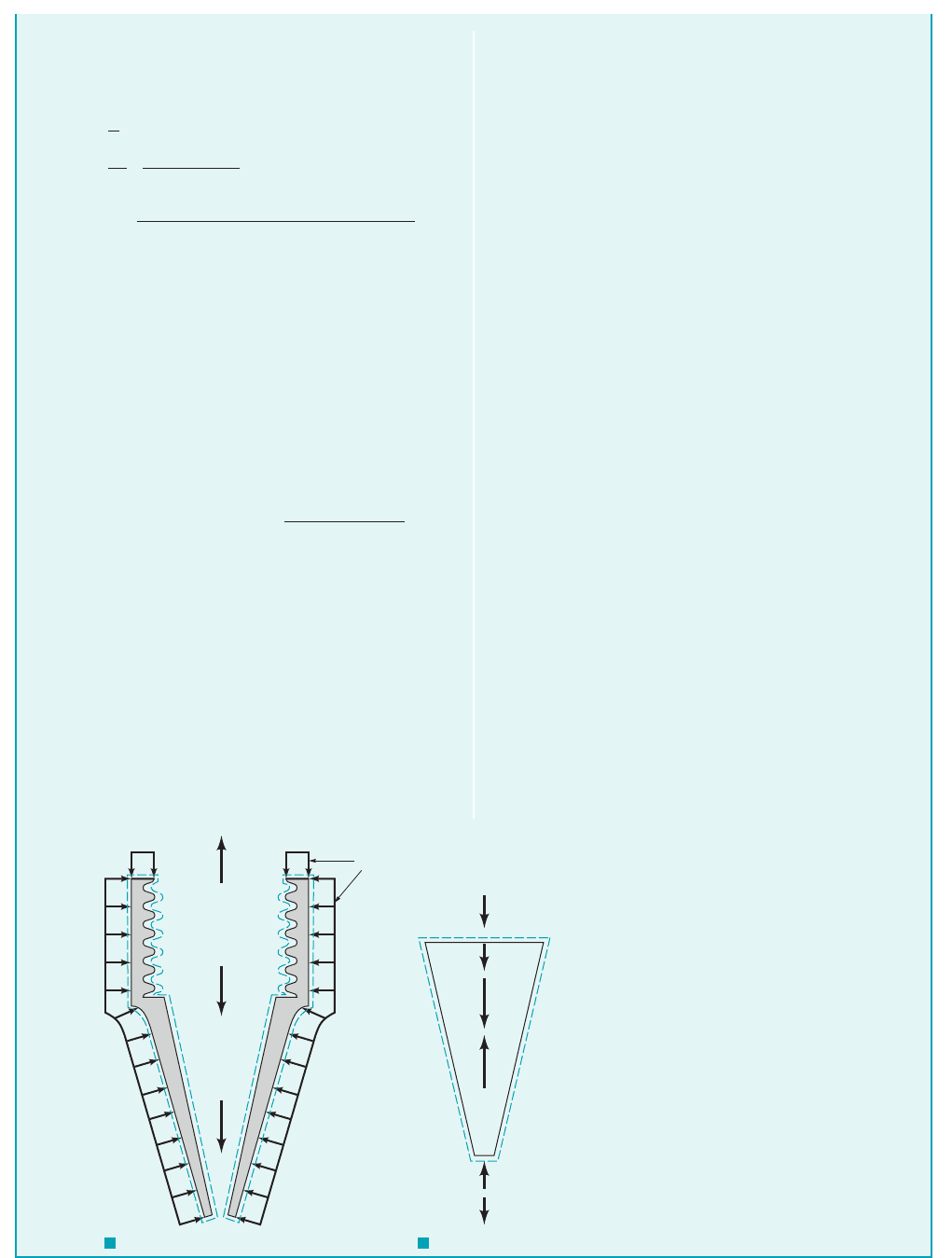
COMMENT The control volume selected above to solve
problems such as these is not unique. The following is an alternate
solution that involves two other control volumes—one containing
F
A
,
77.8 N
F
A
16.5 N 0.981 N 93.3 N 0.0278 N
0.0278 N 0
1464 kPa211000 Pa
kPa2
p116 mm2
2
411000
2
mm
2
m
2
2
F
A
10.599 kg
s212.98 m
s 30.6 m
s2 0.981 N
F
A
,
p
2
,
0.0278 N
w
w
1999 kg
m
3
212.84 10
6
m
3
219.81 m
s
2
2
2.84 10
6
m
3
c
116 mm2
2
15 mm2
2
116 mm215 mm2
11000
2
mm
2
m
2
2
d
1
12
p
130 mm2
11000 mm
m2
V
w
1
12
ph1D
2
1
D
2
2
D
1
D
2
2
w
w
r V
w
g
only the nozzle and the other containing only the water in the noz-
zle. These control volumes are shown in Figs. E5.11c and E5.11d
along with the vertical forces acting on the contents of each con-
trol volume. The new force involved, represents the interaction
between the water and the conical inside surface of the nozzle. It
includes the net pressure and viscous forces at this interface.
Application of Eq. 5.22 to the contents of the control volume
of Fig. E5.11c leads to
(12)
The term is the resultant force from the at-
mospheric pressure acting upon the exterior surface of the
nozzle 1i.e., that portion of the surface of the nozzle that is not
in contact with the water2. Recall that the pressure force on a
curved surface 1such as the exterior surface of the nozzle2is
equal to the pressure times the projection of the surface area
on a plane perpendicular to the axis of the nozzle. The projec-
tion of this area on a plane perpendicular to the z direction is
The effect of the atmospheric pressure on the inter-
nal area 1between the nozzle and the water2is already in-
cluded in which represents the net force on this area.
Similarly, for the control volume of Fig. E5.11d we obtain
(13)
where and are gage pressures. From Eq. 13 it is clear that
the value of depends on the value of the atmospheric pressure,
since That is, we must use absolute pressure, not
gage pressure, to obtain the correct value of From Eq. 13 we
can easily identify which forces acting on the flowing fluid
change its velocity magnitude and thus linear momentum.
By combining Eqs. 12 and 13 we obtain the same result for
as before 1Eq. 62:
Note that although the force between the fluid and the nozzle wall,
is a function of the anchoring force, is not. That is, we
were correct in using gage pressure when solving for by means
of the original control volume shown in Fig. E5.11b.
F
A
F
A
,p
atm
,R
z
,
F
A
m
#
1w
1
w
2
2 w
n
p
1
A
1
W
w
p
2
A
2
F
A
R
z
.
A
1
A
2
.
p
atm
,
R
z
p
2
p
1
1p
2
p
atm
2A
2
R
z
m
#
1w
1
w
2
2 w
w
1
p
1
p
atm
2A
1
R
z
A
1
A
2
.
p
atm
1A
1
A
2
2
F
A
w
n
R
z
p
atm
1A
1
A
2
2
R
z
,
(p
1
+ p
atm
)A
1
ᐃ
w
R
z
w
2
(p
2
+ p
atm
)A
2
w
1
(2)
F I G U R E E5.11
c
F I G U R E E5.11
d
F
A
ᐃ
n
R
z
p
atm
JWCL068_ch05_187-262.qxd 9/23/08 9:56 AM Page 205
Several important generalities about the application of the linear momentum equation 1Eq.
5.222are apparent in the example just considered.
1. When the flow is uniformly distributed over a section of the control surface where flow into
or out of the control volume occurs, the integral operations are simplified. Thus, one-
dimensional flows are easier to work with than flows involving nonuniform velocity distri-
butions.
2. Linear momentum is directional; it can have components in as many as three orthogonal
coordinate directions. Furthermore, along any one coordinate, the linear momentum of a
fluid particle can be in the positive or negative direction and thus be considered as a pos-
itive or a negative quantity. In Example 5.11, only the linear momentum in the z direction
was considered 1all of it was in the negative z direction and was hence treated as being
negative2.
3. The flow of positive or negative linear momentum into a control volume involves a nega-
tive product. Momentum flow out of the control volume involves a positive
product. The correct algebraic sign to assign to momentum flow
will depend on the sense of the velocity 1 in positive coordinate direction, in negative
coordinate direction2and the product 1 for flow out of the control volume, for
flow into the control volume2. This is shown in the figure in the margin. In Example 5.11,
the momentum flow into the control volume past section 112was a positive 12quantity
while the momentum flow out of the control volume at section 122was a negative 12quantity.
4. The time rate of change of the linear momentum of the contents of a nondeforming control
volume is zero for steady flow. The momentum problems considered in
this text all involve steady flow.
5. If the control surface is selected so that it is perpendicular to the flow where fluid enters or
leaves the control volume, the surface force exerted at these locations by fluid outside the
control volume on fluid inside will be due to pressure. Furthermore, when subsonic flow ex-
its from a control volume into the atmosphere, atmospheric pressure prevails at the exit cross
section. In Example 5.11, the flow was subsonic and so we set the exit flow pressure at the
atmospheric level. The continuity equation 1Eq. 5.122allowed us to evaluate the fluid flow
velocities and at sections 112and 122.
6. The forces due to atmospheric pressure acting on the control surface may need consideration
as indicated by Eq. 13 in Example 5.11 for the reaction force between the nozzle and the fluid.
When calculating the anchoring force, the forces due to atmospheric pressure on the con-
trol surface cancel each other 1for example, after combining Eqs. 12 and 13 the atmospheric
pressure forces are no longer involved2and gage pressures may be used.
7. The external forces have an algebraic sign, positive if the force is in the assigned positive
coordinate direction and negative otherwise.
8. Only external forces acting on the contents of the control volume are considered in the lin-
ear momentum equation 1Eq. 5.222. If the fluid alone is included in a control volume, reac-
tion forces between the fluid and the surface or surfaces in contact with the fluid [wetted
surface1s2] will need to be in Eq. 5.22. If the fluid and the wetted surface or surfaces are
within the control volume, the reaction forces between fluid and wetted surface1s2do not ap-
pear in the linear momentum equation 1Eq. 5.222because they are internal, not external forces.
The anchoring force that holds the wetted surface1s2in place is an external force, however,
and must therefore be in Eq. 5.22.
9. The force required to anchor an object will generally exist in response to surface pressure
and兾or shear forces acting on the control surface, to a change in linear momentum flow
through the control volume containing the object, and to the weight of the object and the
fluid contained in the control volume. In Example 5.11 the nozzle anchoring force was re-
quired mainly because of pressure forces and partly because of a change in linear momen-
tum flow associated with accelerating the fluid in the nozzle. The weight of the water and
the nozzle contained in the control volume influenced the size of the anchoring force only
slightly.
F
A
,
w
2
w
1
1i.e., 0
Ⲑ
0t
兰
cv
Vr dV⫺2
⫺
⫹
⫺⫹V ⴢ nˆ
⫺⫹
1VrV ⴢ nˆ dA21⫹ or ⫺2
V ⴢ nˆV ⴢ nˆ
206 Chapter 5 ■ Finite Control Volume Analysis
Control
volume
x
y
Vr V⭈
n > 0
^
Vr V⭈n < 0
^
n
^
n
^
VV
n
^
n
^
VV
V5.7 Running on
water
A control volume
diagram is similar
to a free-body
diagram.
JWCL068_ch05_187-262.qxd 9/23/08 9:56 AM Page 206