Munson B.R. Fundamentals of Fluid Mechanics
Подождите немного. Документ загружается.

this summation 1in the limit of 2takes the form of an integration over all the particles in
the system and can be written as
The limits of integration cover the entire system—a 1usually2moving volume. We have used the
fact that the amount of B in a fluid particle of mass is given in terms of b by
Most of the laws governing fluid motion involve the time rate of change of an extensive property
of a fluid system—the rate at which the momentum of a system changes with time, the rate at which
the mass of a system changes with time, and so on. Thus, we often encounter terms such as
(4.8)
To formulate the laws into a control volume approach, we must obtain an expression for the time
rate of change of an extensive property within a control volume, not within a system. This can
be written as
(4.9)
where the limits of integration, denoted by cv, cover the control volume of interest. Although Eqs.
4.8 and 4.9 may look very similar, the physical interpretation of each is quite different.
Mathematically, the difference is represented by the difference in the limits of integration. Recall
that the control volume is a volume in space 1in most cases stationary, although if it moves it need
not move with the system2. On the other hand, the system is an identifiable collection of mass that
moves with the fluid 1indeed it is a specified portion of the fluid2. We will learn that even for those
instances when the control volume and the system momentarily occupy the same volume in space,
the two quantities and need not be the same. The Reynolds transport theorem
provides the relationship between the time rate of change of an extensive property for a system
and that for a control volume—the relationship between Eqs. 4.8 and 4.9.
dB
cv
Ⲑ
dtdB
sys
Ⲑ
dt
dB
cv
dt
⫽
d a
冮
cv
rb dV⫺b
dt
B
cv
,
dB
sys
dt
⫽
d a
冮
sys
rb dV⫺b
dt
dB ⫽ br dV⫺.r dV⫺
B
sys
⫽ lim
dV⫺S0
a
i
b
i
1r
i
dV⫺
i
2⫽
冮
sys
rb dV⫺
dV⫺ S 0
4.4 The Reynolds Transport Theorem 167
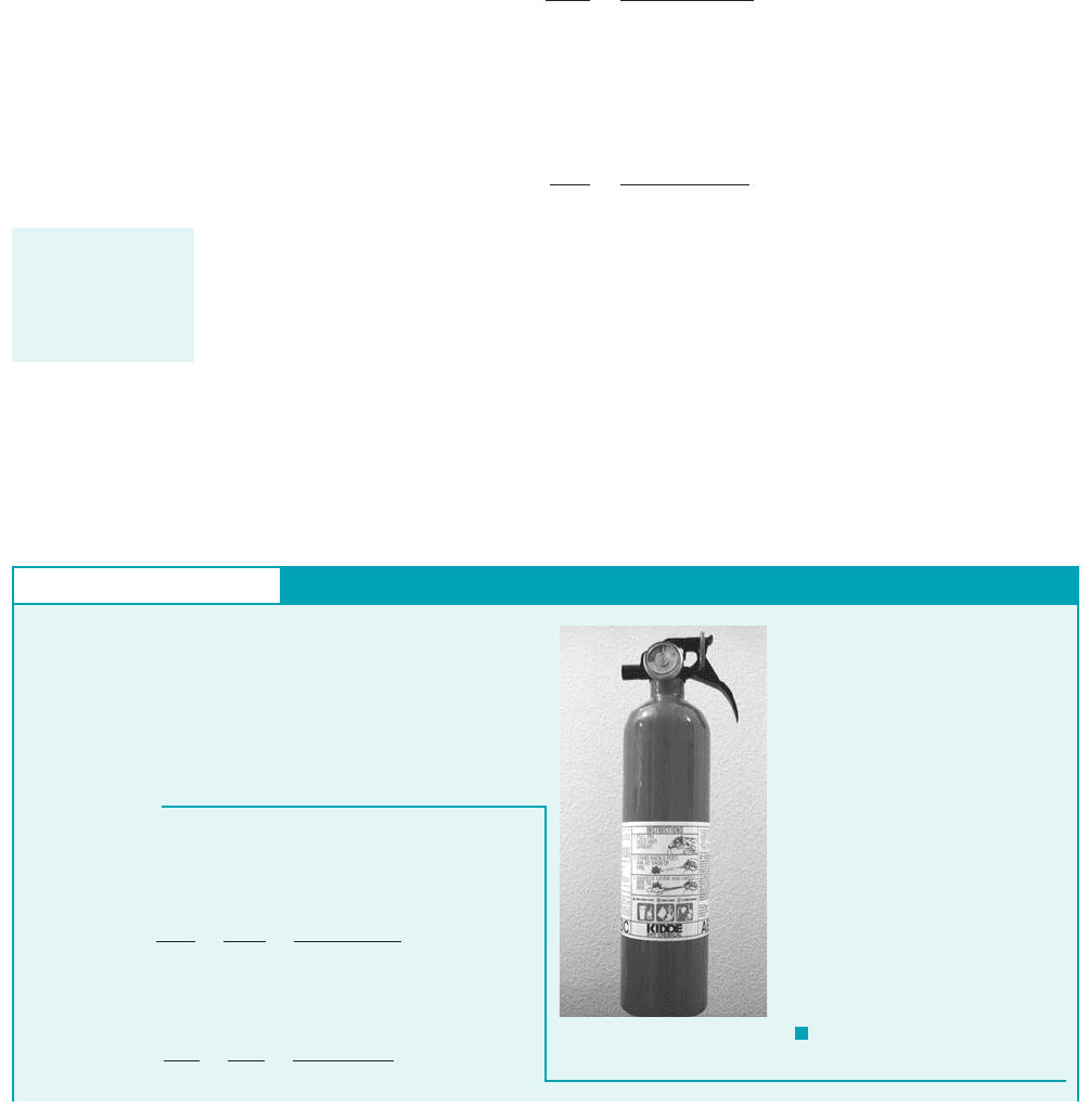
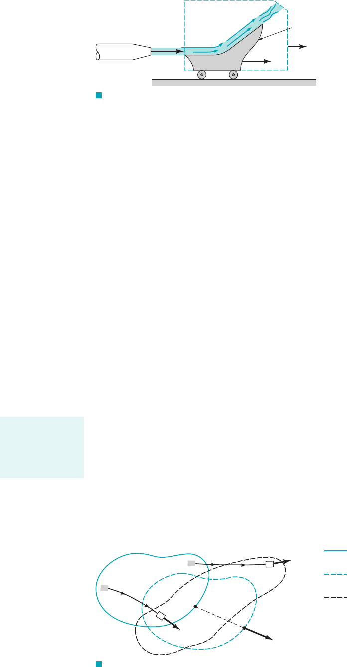
GIVEN Fluid flows from the fire extinguisher tank shown in
Fig. E4.7a.
FIND Discuss the differences between and if B
represents mass.
dB
cv
Ⲑ
dtdB
sys
Ⲑ
dt
S
OLUTION
F I G U R E E4.7
Time Rate of Change for a System and a Control Volume
E
XAMPLE 4.7
With the system mass, it follows that and Eqs. 4.8
and 4.9 can be written as
and
dB
cv
dt
⬅
dm
cv
dt
⫽
d a
冮
cv
r dV⫺b
dt
dB
sys
dt
⬅
dm
sys
dt
⫽
d a
冮
sys
r dV⫺b
dt
b ⫽ 1B ⫽ m,
(a)
Differences be-
tween control vol-
ume and system
concepts are subtle
but very important.
JWCL068_ch04_147-186.qxd 8/19/08 8:51 PM Page 167
4.4.1 Derivation of the Reynolds Transport Theorem
A simple version of the Reynolds transport theorem relating system concepts to control volume
concepts can be obtained easily for the one-dimensional flow through a fixed control volume such
as the variable area duct section shown in Fig. 4.11a. We consider the control volume to be that
stationary volume within the duct between sections 112and 122as indicated in Fig. 4.11b. The system
that we consider is that fluid occupying the control volume at some initial time t. A short time
later, at time the system has moved slightly to the right. The fluid particles that coincided
with section 122of the control surface at time t have moved a distance to the right,
where is the velocity of the fluid as it passes section 122. Similarly, the fluid initially at section
112has moved a distance where is the fluid velocity at section 112. We assume the
fluid flows across sections 112and 122in a direction normal to these surfaces and that and are
constant across sections 112and 122.
As is shown in Fig. 4.11c, the outflow from the control volume from time t to is denoted
as volume II, the inflow as volume I, and the control volume itself as CV. Thus, the system at time
t consists of the fluid in section CV; that is, At time the system
consists of the same fluid that now occupies sections That is,
at time The control volume remains as section CV for all time.t dt.
“SYS CV I II”1CV I2 II.
t dt“SYS CV” at time t.
t dt
V
2
V
1
V
1
d/
1
V
1
dt,
V
2
d/
2
V
2
dt
t dt,
168 Chapter 4 ■ Fluid Kinematics
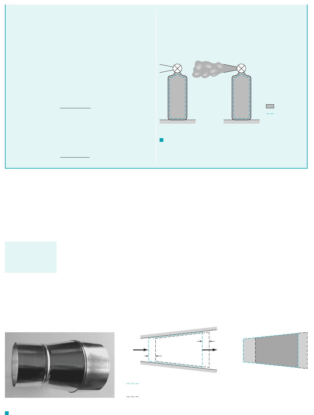
Physically these represent the time rate of change of mass within
the system and the time rate of change of mass within the control
volume, respectively. We choose our system to be the fluid within
the tank at the time the valve was opened and the control
volume to be the tank itself as shown in Fig. E4.7b. A short time
after the valve is opened, part of the system has moved outside of
the control volume as is shown in Fig. E4.7c. The control volume
remains fixed. The limits of integration are fixed for the control
volume; they are a function of time for the system.
Clearly, if mass is to be conserved 1one of the basic laws gov-
erning fluid motion2, the mass of the fluid in the system is con-
stant, so that
Onthe other hand,it is equallyclear that some ofthe fluid hasleft the
control volumethrough the nozzle on the tank. Hence, the amount of
mass within the tank 1the control volume2decreases with time, or
d a
冮
cv
r dVb
dt
6 0
d a
冮
sys
r dVb
dt
0
1t 02
The actual numerical value of the rate at which the mass in the
control volume decreases will depend on the rate at which the fluid
flows through the nozzle 1i.e., the size of the nozzle and the speed
and density of the fluid2. Clearly the meanings of and
are different. For this example, Other
situations may have dB
cv
dt dB
sys
dt.
dB
cv
dt 6 dB
sys
dt.dB
cv
dt
dB
sys
dt
F I G U R E E4.7
(b)(c)
System
Control
surface
t = 0 t > 0
V
1
V
2
ᐉ
1
= V
1
t
δδ
(1)
(2)
ᐉ
2
= V
2
t
δδ
Fixed control surface and system
boundary at time
t
System boundary at time t + t
δ
(b)(c)
I IICV – I
(2)
(1)
F I G U R E 4.11 Control volume and system for flow through a variable area pipe.
The moving system
flows through the
fixed control
volume.
(a)
JWCL068_ch04_147-186.qxd 8/19/08 8:51 PM Page 168
If B is an extensive parameter of the system, then the value of it for the system at time
t is
since the system and the fluid within the control volume coincide at this time. Its value at time
is
Thus, the change in the amount of B in the system in the time interval divided by this time
interval is given by
By using the fact that at the initial time t we have this ungainly expression may
be rearranged as follows.
(4.10)
In the limit the left-hand side of Eq. 4.10 is equal to the time rate of change of B for the
system and is denoted as We use the material derivative notation, to denote this
time rate of change to emphasize the Lagrangian character of this term. 1Recall from Section 4.2.1
that the material derivative, of any quantity P represents the time rate of change of that
quantity associated with a given fluid particle as it moves along.2Similarly, the quantity
represents the time rate of change of property B associated with a system 1a given portion of fluid2
as it moves along.
In the limit the first term on the right-hand side of Eq. 4.10 is seen to be the time
rate of change of the amount of B within the control volume
(4.11)
The third term on the right-hand side of Eq. 4.10 represents the rate at which the extensive parameter
B flows from the control volume, across the control surface. As indicated by the figure in the
margin, during the time interval from to the volume of fluid that flows across section
122is given by Thus, the amount of B within region II, the outflow
region, is its amount per unit volume, times the volume
where and are the constant values of b and across section 122. Thus, the rate at which this
property flows from the control volume, is given by
(4.12)
Similarly, the inflow of B into the control volume across section 112during the time interval
corresponds to that in region I and is given by the amount per unit volume times the volume,
Hence,
where and are the constant values of b and across section 112. Thus, the rate of inflow of
the property B into the control volume, is given by
(4.13)B
#
in
⫽
lim
dtS0
B
I
1t ⫹ dt2
dt
⫽ r
1
A
1
V
1
b
1
B
#
in
,
rr
1
b
1
B
I
1t ⫹ dt2⫽ 1r
1
b
1
21d V⫺
1
2⫽ r
1
b
1
A
1
V
1
dt
dV⫺
I
⫽ A
1
d/
1
⫽ A
1
1V
1
dt2.
dt
B
#
out
⫽
lim
dtS0
B
II
1t ⫹ dt2
dt
⫽ r
2
A
2
V
2
b
2
B
#
out
,
rr
2
b
2
B
II
1t ⫹ dt2⫽ 1r
2
b
2
21d V⫺
II
2⫽ r
2
b
2
A
2
V
2
dt
rb,
dV⫺
II
⫽ A
2
d/
2
⫽ A
2
1V
2
dt2.
t ⫽ dtt ⫽ 0
lim
dtS0
B
cv
1t ⫹ dt2⫺ B
cv
1t2
dt
⫽
0B
cv
0t
⫽
0 a
冮
cv
rb dV⫺b
0t
dt S 0,
DB
sys
Ⲑ
Dt
DP
Ⲑ
Dt,
D12
Ⲑ
Dt,DB
sys
Ⲑ
Dt.
dt S 0,
dB
sys
dt
⫽
B
cv
1t ⫹ dt2⫺ B
cv
1t2
dt
⫺
B
I
1t ⫹ dt2
dt
⫹
B
II
1t ⫹ dt2
dt
B
sys
1t2⫽ B
cv
1t2,
dB
sys
dt
⫽
B
sys
1t ⫹ dt2⫺ B
sys
1t2
dt
⫽
B
cv
1t ⫹ dt2⫺ B
I
1t ⫹ dt2⫹ B
II
1t ⫹ dt2⫺ B
sys
1t2
dt
dt
B
sys
1t ⫹ dt2⫽ B
cv
1t ⫹ dt2⫺ B
I
1t ⫹ dt2⫹ B
II
1t ⫹ dt2
t ⫹ dt
B
sys
1t2⫽ B
cv
1t2
4.4 The Reynolds Transport Theorem 169
V
2
(2)
t = 0
V
2
t
(2)
t = t
V
II
δ
δ
δ
The time rate of
change of a system
property is a La-
grangian concept.
JWCL068_ch04_147-186.qxd 8/19/08 8:51 PM Page 169

If we combine Eqs. 4.10, 4.11, 4.12, and 4.13 we see that the relationship between the time
rate of change of B for the system and that for the control volume is given by
(4.14)
or
(4.15)
This is a version of the Reynolds transport theorem valid under the restrictive assumptions
associated with the flow shown in Fig. 4.11—fixed control volume with one inlet and one outlet
having uniform properties 1density, velocity, and the parameter b2across the inlet and outlet with
the velocity normal to sections 112and 122. Note that the time rate of change of B for the system
1the left-hand side of Eq. 4.15 or the quantity in Eq. 4.82is not necessarily the same as the rate
of change of B within the control volume 1the first term on the right-hand side of Eq. 4.15 or the
quantity in Eq. 4.92. This is true because the inflow rate and the outflow rate
of the property B for the control volume need not be the same.
1b
2
r
2
V
2
A
2
21b
1
r
1
V
1
A
1
2
DB
sys
Dt
⫽
0B
cv
0t
⫹ r
2
A
2
V
2
b
2
⫺ r
1
A
1
V
1
b
1
DB
sys
Dt
⫽
0B
cv
dt
⫹ B
#
out
⫺ B
#
in
170 Chapter 4 ■ Fluid Kinematics
The time derivative
associated with a
system may be dif-
ferent from that for
a control volume.
GIVEN Consider again the flow from the fire extinguisher
shown in Fig. E4.7. Let the extensive property of interest be the
system mass 1 the system mass, or 2.b ⫽ 1B ⫽ m,
Use of the Reynolds Transport Theorem
E
XAMPLE 4.8
FIND Write the appropriate form of the Reynolds transport
theorem for this flow.
S
OLUTION
The physical interpretation of this result is that the rate at which
the mass in the tank decreases in time is equal in magnitude but
opposite to the rate of flow of mass from the exit, Note
the units for the two terms of Eq. 2 1kg兾s or slugs兾s2. Note that
if there were both an inlet and an outlet to the control volume
shown in Fig. E4.7, Eq. 2 would become
(3)
In addition, if the flow were steady, the left-hand side of Eq. 3
would be zero 1the amount of mass in the control would be con-
stant in time2and Eq. 3 would become
This is one form of the conservation of mass principle discussed in
Sect. 3.6.2—the mass flowrates into and out of the control volume
are equal. Other more general forms are discussed in Chapter 5.
r
1
A
1
V
1
⫽ r
2
A
2
V
2
0 a
冮
cv
r
d⫺Vb
0t
⫽ r
1
A
1
V
1
⫺ r
2
A
2
V
2
r
2
A
2
V
2
.
Again we take the control volume to be the fire extinguisher, and
the system to be the fluid within it at time For this case
there is no inlet, section 112, across which the fluid flows into the
control volume There is, however, an outlet, section 122.
Thus, the Reynolds transport theorem, Eq. 4.15, along with Eq.
4.9 with can be written as
(1)
(Ans)
COMMENT
If we proceed one step further and use the basic
law of conservation of mass, we may set the left-hand side of this
equation equal to zero 1the amount of mass in a system is con-
stant2and rewrite Eq. 1 in the form
(2)
0 a
冮
cv
r
dV⫺b
0t
⫽⫺r
2
A
2
V
2
Dm
sys
Dt
⫽
0 a
冮
cv
r
dV⫺b
0t
⫹ r
2
A
2
V
2
b ⫽ 1
1A
1
⫽ 02.
t ⫽ 0.
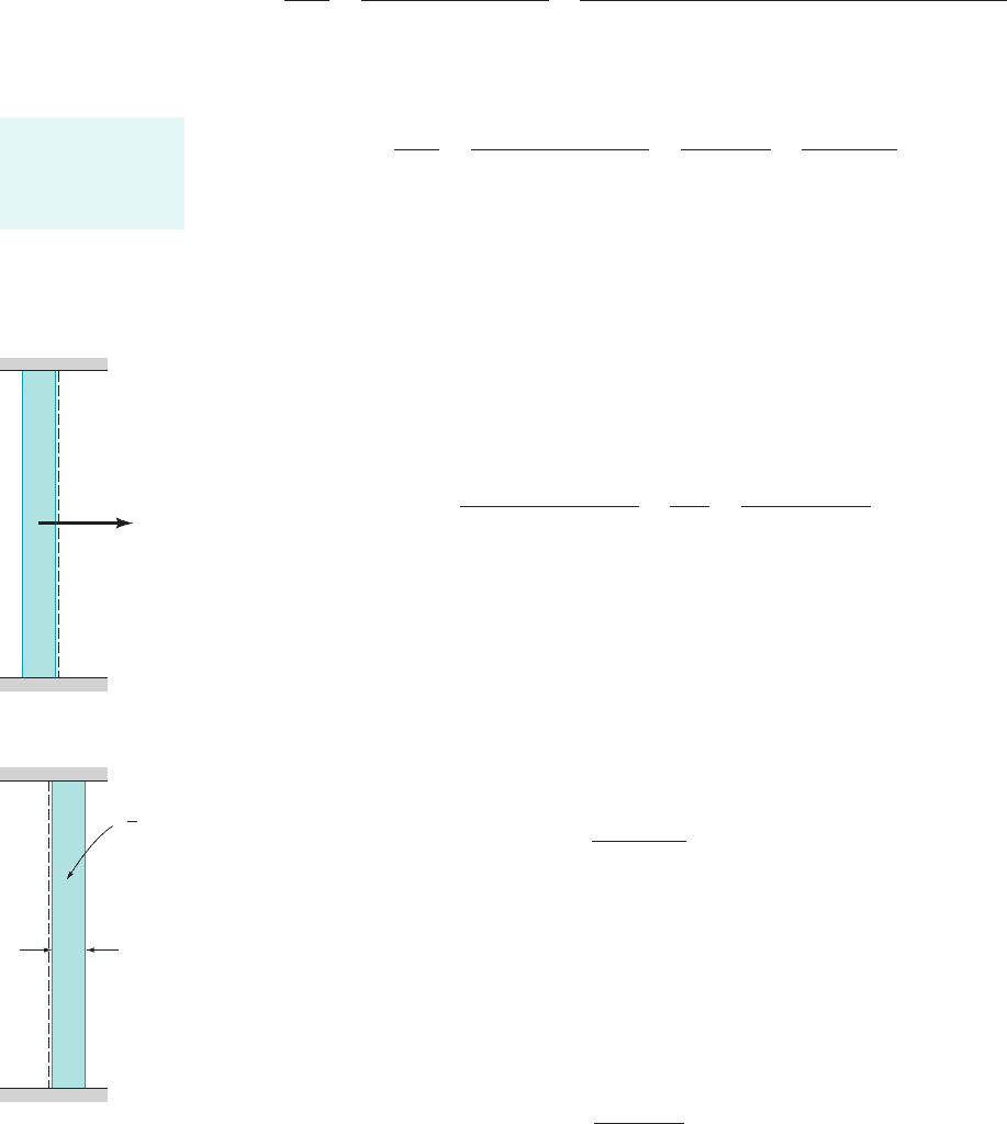
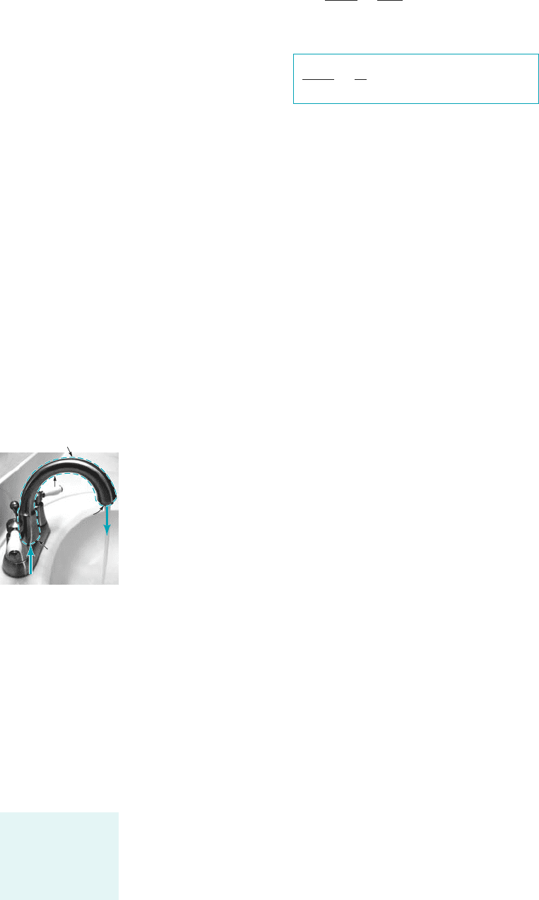
Equation 4.15 is a simplified version of the Reynolds transport theorem. We will now derive
it for much more general conditions. A general, fixed control volume with fluid flowing through
it is shown in Fig. 4.12. The flow field may be quite simple 1as in the above one-dimensional flow
considerations2, or it may involve a quite complex, unsteady, three-dimensional situation such as
the flow through a human heart as illustrated by the figure in the margin. In any case we again
consider the system to be the fluid within the control volume at the initial time t. A short time
later a portion of the fluid 1region II2has exited from the control volume and additional fluid
1region I, not part of the original system2has entered the control volume.
Left
Atrium
Right
Atrium
Right
Ventricle
Left
Ventricle
JWCL068_ch04_147-186.qxd 8/19/08 8:51 PM Page 170
We consider an extensive fluid property B and seek to determine how the rate of change of B
associated with the system is related to the rate of change of B within the control volume at any
instant. By repeating the exact steps that we did for the simplified control volume shown in Fig.
4.11, we see that Eq. 4.14 is valid for the general case also, provided that we give the correct
interpretation to the terms and In general, the control volume may contain more 1or less2
than one inlet and one outlet. A typical pipe system may contain several inlets and outlets as are
shown in Fig. 4.13. In such instances we think of all inlets grouped together
and all outlets grouped together at least conceptually.
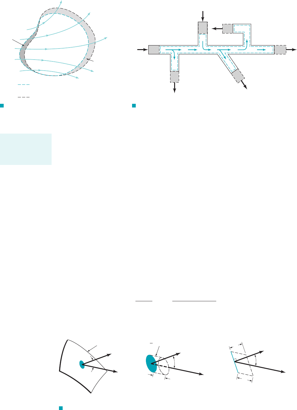
The term represents the net flowrate of the property B from the control volume. Its
value can be thought of as arising from the addition 1integration2of the contributions through
each infinitesimal area element of size on the portion of the control surface dividing region
II and the control volume. This surface is denoted As is indicated in Fig. 4.14, in time
the volume of fluid that passes across each area element is given by where
is the height 1normal to the base, 2of the small volume element, and is the
angle between the velocity vector and the outward pointing normal to the surface, Thus,
since the amount of the property B carried across the area element in the time
interval is given by
The rate at which B is carried out of the control volume across the small area element denoted
is
dB
#
out
⫽
lim
d
t
S0
rb dV⫺
dt
⫽
lim
d
t
S0
1rbV cos u dt2 dA
dt
⫽ rbV cos u dA
dB
#
out
,
dA,
dB ⫽ br dV⫺⫽br1V cos u dt2 dA
dt
dAd/ ⫽ V dt,
nˆ.
udAd/
n
⫽ d/ cos u
dV⫺⫽d/
n
dA,
dtCS
out
.
dA
B
#
out
II
c
⫹
p
2,1II ⫽ II
a
⫹ II
b
⫹
1I ⫽ I
a
⫹ I
b
⫹ I
c
⫹
p
2
B
#
in
.B
#
out
4.4 The Reynolds Transport Theorem 171
F I G U R E 4.12 Control volume
and system for flow through an arbitrary, fixed
control volume.
CV–I
II
I
Inflow
Outflow
Fixed control surface and system
boundary at time
t
System boundary at time t + t
δ
The simplified
Reynolds transport
theorem can be
easily generalized.
V
1
V
6
V
4
V
2
V
3
V
5
I
a
II
a
I
b
II
c
II
b
II
d
F I G U R E 4.13 Typical control volume with more than one
inlet and outlet.
n
V
A
δ
CS
out
Outflow
portion of
control
surface
θ
(a)(b)(c)
ᐉ = V t
δδ
θ
^
n
^
V
V = ᐉ
n
A
δ δδ
A
δ
V
n
^
ᐉ
δ
ᐉ
n
δ
θ
F I G U R E 4.14 Outflow across a typical portion of the control surface.
JWCL068_ch04_147-186.qxd 8/19/08 8:51 PM Page 171
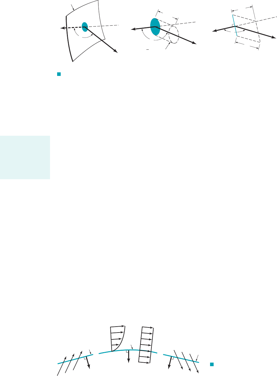
By integrating over the entire outflow portion of the control surface, we obtain
The quantity is the component of the velocity normal to the area element From the
definition of the dot product, this can be written as Hence, an alternate form of
the outflow rate is
(4.16)
In a similar fashion, by considering the inflow portion of the control surface, as shown
in Fig. 4.15, we find that the inflow rate of B into the control volume is
(4.17)
We use the standard notation that the unit normal vector to the control surface, points out from the
control volume. Thus, as is shown in Fig. 4.16, for outflow regions 1the normal
component of V is positive; 2. For inflow regions 1the normal component
of V is negative; 2. The value of is, therefore, positive on the portions of the
control surface and negative on the portions. Over the remainder of the control surface, there is
no inflow or outflow, leading to on those portions. On such portions either
1the fluid “sticks” to the surface2or 1the fluid “slides”along the surface without crossing it2
1see Fig. 4.162. Therefore, the net flux 1flowrate2of parameter B across the entire control surface is
(4.18)
where the integration is over the entire control surface.
⫽
冮
cs
rbV ⴢ nˆ dA
B
#
out
⫺ B
#
in
⫽
冮
cs
out
rbV ⴢ nˆ dA ⫺ a⫺
冮
cs
in
rbV ⴢ nˆ dAb
cos u ⫽ 0
V ⫽ 0V ⴢ nˆ ⫽ V cos u ⫽ 0
CV
in
CV
out
cos uV ⴢ nˆ 6 0
90° 6 u 6 270°V ⴢ nˆ 7 0
⫺90° 6 u 6 90°
nˆ,
B
#
in
⫽⫺
冮
cs
in
rbV cos u dA ⫽⫺
冮
cs
in
rbV ⴢ nˆ dA
CS
in
,
B
#
out
⫽
冮
cs
out
rbV ⴢ nˆ dA
V cos u ⫽ V ⴢ nˆ.
dA.V cos u
B
#
out
⫽
冮
cs
out
dB
#
out
⫽
冮
cs
out
rbV cos u dA
CS
out
,
172 Chapter 4 ■ Fluid Kinematics
n
^
V
(
a)
CS
in
Inflow
portion of
control surface
A
δ
θ
n
^
θ
ᐉ = V t
δδ
V = ᐉ
n
A
δδδ
V
V
n
^
ᐉ
δ
ᐉ
n
δ
θ
(b)(c)
F I G U R E 4.15 Inflow across a typical portion of the control surface.
V
•
n < 0
V = 0
^
V
•
n = 0
^
V
•
n > 0
^
n
^
n
^
n
^
CS
in
CS
out
CS
(a)(b)(c)
F I G U R E 4.16
Possible velocity configurations
on portions of the control sur-
face: (a) inflow, (b) no flow
across the surface, (c) outflow.
The flowrate of a
parameter across
the control surface
is written in terms
of a surface inte-
gral.
JWCL068_ch04_147-186.qxd 8/19/08 8:52 PM Page 172
By combining Eqs. 4.14 and 4.18 we obtain
This can be written in a slightly different form by using so that
(4.19)
Equation 4.19 is the general form of the Reynolds transport theorem for a fixed, nondeforming
control volume. Its interpretation and use are discussed in the following sections.
4.4.2 Physical Interpretation
The Reynolds transport theorem as given in Eq. 4.19 is widely used in fluid mechanics 1and other
areas as well2. At first it appears to be a rather formidable mathematical expression—perhaps one
to be steered clear of if possible. However, a physical understanding of the concepts involved will
show that it is a rather straightforward, relatively easy-to-use tool. Its purpose is to provide a link
between control volume ideas and system ideas.
The left side of Eq. 4.19 is the time rate of change of an arbitrary extensive parameter of a
system. This may represent the rate of change of mass, momentum, energy, or angular momentum
of the system, depending on the choice of the parameter B.
Because the system is moving and the control volume is stationary, the time rate of change
of the amount of B within the control volume is not necessarily equal to that of the system. The first
term on the right side of Eq. 4.19 represents the rate of change of B within the control volume as
the fluid flows through it. Recall that b is the amount of B per unit mass, so that is the amount
of B in a small volume Thus, the time derivative of the integral of throughout the control
volume is the time rate of change of B within the control volume at a given time.
The last term in Eq. 4.19 1an integral over the control surface2represents the net flowrate of
the parameter B across the entire control surface. As illustrated by the figure in the margin, over a
portion of the control surface this property is being carried out of the control volume
over other portions it is being carried into the control volume Over the remainder of
the control surface there is no transport of B across the surface since because either
or V is parallel to the surface at those locations. The mass flowrate through area
element given by is positive for outflow 1efflux2and negative for inflow 1influx2.
Each fluid particle or fluid mass carries a certain amount of B with it, as given by the product of
B per unit mass, b, and the mass. The rate at which this B is carried across the control surface is
given by the area integral term of Eq. 4.19. This net rate across the entire control surface may be
negative, zero, or positive depending on the particular situation involved.
4.4.3 Relationship to Material Derivative
In Section 4.2.1 we discussed the concept of the material derivative
The physical interpretation of this derivative is that it
provides the time rate of change of a fluid property 1temperature, velocity, etc.2associated with a
particular fluid particle as it flows. The value of that parameter for that particle may change because
of unsteady effects [the term] or because of effects associated with the particle’s motion
[the term].
Careful consideration of Eq. 4.19 indicates the same type of physical interpretation for the
Reynolds transport theorem. The term involving the time derivative of the control volume integral
represents unsteady effects associated with the fact that values of the parameter within the control
volume may change with time. For steady flow this effect vanishes—fluid flows through the control
volume but the amount of any property, B, within the control volume is constant in time. The term
involving the control surface integral represents the convective effects associated with the flow of the
system across the fixed control surface. The sum of these two terms gives the rate of change of the
parameter B for the system. This corresponds to the interpretation of the material derivative,
V ⴢ § 12
012
Ⲑ
0t
0120t ⫹ u 0120x ⫹ v 012
Ⲑ
0y ⫹ w 012
Ⲑ
0z.
D12
Ⲑ
Dt ⫽ 012
Ⲑ
0t ⫹ V ⴢ §12⫽
rV ⴢ nˆ dA,dA,
V ⫽ 0,b ⫽ 0,
bV ⴢ nˆ ⫽ 0,
1V ⴢ nˆ 6 02.
1V ⴢ nˆ 7 02;
rbdV⫺.
rb dV⫺
DB
sys
Dt
⫽
0
0t
cv
rb dV⫺⫹
cs
rb V ⴢ nˆ dA
B
cv
⫽
cv
rb dV⫺
DB
sys
Dt
⫽
0B
cv
0t
⫹
cs
rbV ⴢ nˆ dA
4.4 The Reynolds Transport Theorem 173
V
•
n < 0
^
V
•
n = 0
^
V
•
n > 0
^
Control surface
The Reynolds trans-
port theorem is the
integral counter-
part of the material
derivative.
JWCL068_ch04_147-186.qxd 8/19/08 8:52 PM Page 173
in which the sum of the unsteady effect and the convective effect
gives the rate of change of a parameter for a fluid particle. As is discussed in Section 4.2, the material
derivative operator may be applied to scalars 1such as temperature2or vectors 1such as velocity2. This
is also true for the Reynolds transport theorem. The particular parameters of interest, B and b, may
be scalars or vectors.
Thus, both the material derivative and the Reynolds transport theorem equations represent
ways to transfer from the Lagrangian viewpoint 1follow a particle or follow a system2to the Eulerian
viewpoint 1observe the fluid at a given location in space or observe what happens in the fixed
control volume2. The material derivative 1Eq. 4.52is essentially the infinitesimal 1or derivative2
equivalent of the finite size 1or integral2Reynolds transport theorem 1Eq. 4.192.
4.4.4 Steady Effects
Consider a steady flow so that Eq. 4.19 reduces to
(4.20)
In such cases if there is to be a change in the amount of B associated with the system 1nonzero
left-hand side2, there must be a net difference in the rate that B flows into the control volume
compared with the rate that it flows out of the control volume. That is, the integral of over
the inflow portions of the control surface would not be equal and opposite to that over the outflow
portions of the surface.
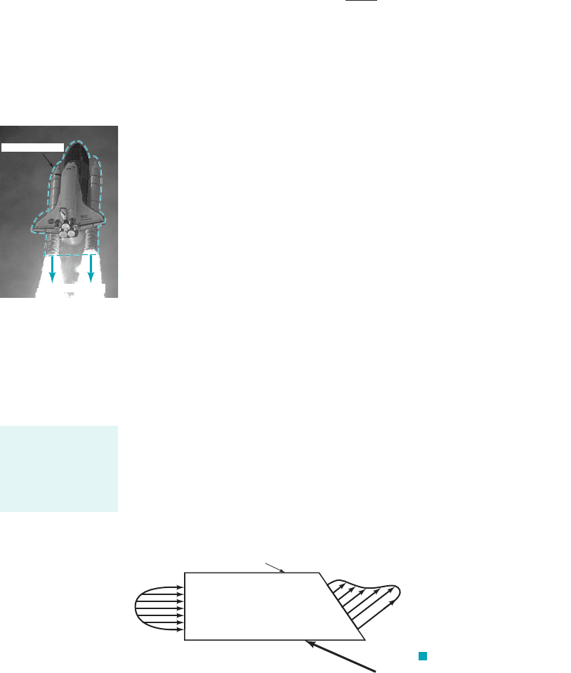
Consider steady flow through the “black box” control volume that is shown in Fig. 4.17. If
the parameter B is the mass of the system, the left-hand side of Eq. 4.20 is zero 1conservation of
mass for the system as discussed in detail in Section 5.12. Hence, the flowrate of mass into the
box must be the same as the flowrate of mass out of the box because the right-hand side of Eq.
4.20 represents the net flowrate through the control surface. On the other hand, assume the
parameter B is the momentum of the system. The momentum of the system need not be constant.
In fact, according to Newton’s second law the time rate of change of the system momentum equals
the net force, F, acting on the system. In general, the left-hand side of Eq. 4.20 will therefore be
nonzero. Thus, the right-hand side, which then represents the net flux of momentum across the
control surface, will be nonzero. The flowrate of momentum into the control volume need not be
the same as the flux of momentum from the control volume. We will investigate these concepts
much more fully in Chapter 5. They are the basic principles describing the operation of such
devices as jet or rocket engines like the one shown in the figure in the margin.
For steady flows the amount of the property B within the control volume does not change
with time. The amount of the property associated with the system may or may not change with
time, depending on the particular property considered and the flow situation involved. The difference
between that associated with the control volume and that associated with the system is determined
by the rate at which B is carried across the control surface—the term
4.4.5 Unsteady Effects
Consider unsteady flow so that all terms in Eq. 4.19 must be retained. When they
are viewed from a control volume standpoint, the amount of parameter B within the system may
change because the amount of B within the fixed control volume may change with time
3012
0t 04
cs
rbV ⴢ nˆ dA.
rbV ⴢ nˆ
DB
sys
Dt
cs
rbV ⴢ nˆ dA
3012
0t 04
D12
Dt 012
0t V ⴢ §12,
174 Chapter 4 ■ Fluid Kinematics
F
V
out
V
in
Control volume
F I G U R E 4.17 Steady flow
through a control volume.
(Photograph courtesy
of NASA.)
Control volume
Momentum out
The Reynolds
transport theorem
involves both
steady and un-
steady effects.
JWCL068_ch04_147-186.qxd 8/19/08 8:52 PM Page 174
and because there may be a net nonzero flow of that parameter across
the control surface 1the term2.
For the special unsteady situations in which the rate of inflow of parameter B is exactly
balanced by its rate of outflow, it follows that and Eq. 4.19 reduces to
(4.21)
For such cases, any rate of change in the amount of B associated with the system is equal to the
rate of change of B within the control volume. This can be illustrated by considering flow through
a constant diameter pipe as is shown in Fig. 4.18. The control volume is as shown, and the system
is the fluid within this volume at time We assume the flow is one-dimensional with
where is a function of time, and that the density is constant. At any instant in time, all
particles in the system have the same velocity. We let system momentum
where m is the system mass, so that the fluid velocity. The magnitude of
the momentum efflux across the outlet [section 122] is the same as the magnitude of the momentum
influx across the inlet [section 112]. However, the sign of the efflux is opposite to that of the influx
since for the outflow and for the inflow. Note that along the sides
of the control volume. Thus, with on section 112, on section 122, and
,
we obtain
It is seen that for this special case Eq. 4.21 is valid. The rate at which the momentum of the system
changes with time is the same as the rate of change of momentum within the control volume. If
is constant in time, there is no rate of change of momentum of the system and for this special
case each of the terms in the Reynolds transport theorem is zero by itself.
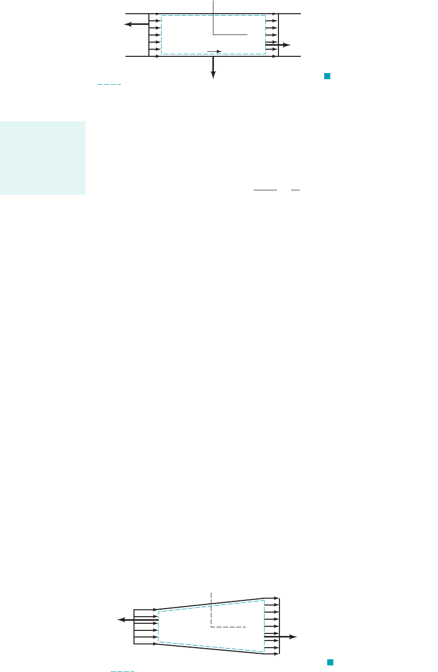
Consider the flow through a variable area pipe shown in Fig. 4.19. In such cases the fluid
velocity is not the same at section 112as it is at 122. Hence, the efflux of momentum from the control
volume is not equal to the influx of momentum, so that the convective term in Eq. 4.20 [the integral
of over the control surface] is not zero. These topics will be discussed in considerably
more detail in Chapter 5.
rV1V ⴢ nˆ 2
V
0
⫽⫺rV
2
0
A
1
i
ˆ
⫹ rV
2
0
A
2
i
ˆ
⫽ 0
⫽
112
r1V
0
i
ˆ
21⫺V
0
2
dA ⫹
122
r1V
0
i
ˆ
21V
0
2
dA
cs
rbV ⴢ nˆ dA ⫽
cs
r1V
0
i
ˆ
21V ⴢ nˆ 2 dA
A
1
⫽ A
2
V ⴢ nˆ ⫽ V
0
V ⴢ nˆ ⫽⫺V
0
V ⴢ nˆ ⫽ 0V ⴢ nˆ 6 0V ⴢ nˆ 7 0
b ⫽ B
Ⲑ
m ⫽ V ⫽ V
0
i
ˆ
,
⫽ mV ⫽ mV
0
i
ˆ
,B ⫽
V
0
1t2
V ⫽ V
0
i
ˆ
,t
0
.
DB
sys
Dt
⫽
0
0t
cv
rb dV⫺
cs
rbV ⴢ nˆ dA ⫽ 0,
cs
rbV ⴢ nˆ dA
3the 01
cv
rb dV⫺2
Ⲑ
0t term4
4.4 The Reynolds Transport Theorem 175
(1)
Control surface
(2)
n = –j
^
V
0
i
V
2
= V
0
(t)
V
1
= V
0
(t)
x
y
^
^
n = –i
^^
n = i
^^
F I G U R E 4.18 Unsteady
flow through a constant diameter pipe.
y
x
(1)
Control surface
(2)
n = –i
^^
n = i
^^
V
1
V
2
< V
1
F I G U R E 4.19 Flow
through a variable area pipe.
For some flow situ-
ations, certain por-
tions of the Reynolds
transport theorem
are automatically
zero.
JWCL068_ch04_147-186.qxd 8/19/08 8:52 PM Page 175
4.4.6 Moving Control Volumes
For most problems in fluid mechanics, the control volume may be considered as a fixed volume
through which the fluid flows. There are, however, situations for which the analysis is simplified
if the control volume is allowed to move or deform. The most general situation would involve a
control volume that moves, accelerates, and deforms. As one might expect, the use of these control
volumes can become fairly complex.
A number of important problems can be most easily analyzed by using a nondeforming
control volume that moves with a constant velocity. Such an example is shown in Fig. 4.20 in
which a stream of water with velocity strikes a vane that is moving with constant velocity
It may be of interest to determine the force, F, that the water puts on the vane. Such problems
frequently occur in turbines where a stream of fluid 1water or steam, for example2strikes a series
of blades that move past the nozzle. To analyze such problems it is advantageous to use a moving
control volume. We will obtain the Reynolds transport theorem for such control volumes.
We consider a control volume that moves with a constant velocity as is shown in Fig. 4.21.
The shape, size, and orientation of the control volume do not change with time. The control volume
merely translates with a constant velocity, as shown. In general, the velocity of the control
volume and the fluid are not the same, so that there is a flow of fluid through the moving control
volume just as in the stationary control volume cases discussed in Section 4.4.2. The main difference
between the fixed and the moving control volume cases is that it is the relative velocity, W, that
carries fluid across the moving control surface, whereas it is the absolute velocity, V, that carries
the fluid across the fixed control surface. The relative velocity is the fluid velocity relative to the
moving control volume—the fluid velocity seen by an observer riding along on the control volume.
The absolute velocity is the fluid velocity as seen by a stationary observer in a fixed coordinate
system.
The difference between the absolute and relative velocities is the velocity of the control
volume, or
(4.22)
Since the velocity is a vector, we must use vector addition as is shown in Fig. 4.22 to obtain the
relative velocity if we know the absolute velocity and the velocity of the control volume. Thus, if
the water leaves the nozzle in Fig. 4.20 with a velocity of and the vane has a velocity
of 1the same as the control volume2, it appears to an observer riding on the vane that
the water approaches the vane with a velocity of In general, the absoluteV
cv
⫽ 80i
ˆ
ft
Ⲑ
s.W ⫽ V ⫺
V
0
⫽ 20i
ˆ
ft
Ⲑ
s
V
1
⫽ 100i
ˆ
ft
Ⲑ
s
V ⫽ W ⫹ V
cv
V
cv
⫽ V ⫺ W,
V
cv
,
V
0
.V
1
176 Chapter 4 ■ Fluid Kinematics
Nozzle
V
0
V
1
V
CV
= V
0
Control volume
moves with speed
V
0
Moving vane
F I G U R E 4.20 Example of a moving control volume.
V
A
V
B
V
CV
= Control volume velocity
At t
1
At t
1
Particle A at t
0
Particle B at t
0
Control volume and system
at time
t
0
Control volume
at time
t
1
> t
0
System at time t
1
> t
0
F I G U R E 4.21 Typical moving control volume and system.
The absolute and
relative velocities
differ by an amount
equal to the control
volume velocity.
JWCL068_ch04_147-186.qxd 8/19/08 8:52 PM Page 176