Munson B.R. Fundamentals of Fluid Mechanics
Подождите немного. Документ загружается.

where and define the location of the moving particle. By
definition, the acceleration of a particle is the time rate of change of its velocity. Since the velocity
may be a function of both position and time, its value may change because of the change in time
as well as a change in the particle’s position. Thus, we use the chain rule of differentiation to obtain
the acceleration of particle A, denoted as
(4.2)
Using the fact that the particle velocity components are given by
and Eq. 4.2 becomes
Since the above is valid for any particle, we can drop the reference to particle A and obtain the
acceleration field from the velocity field as
(4.3)
This is a vector result whose scalar components can be written as
(4.4)
and
where and are the x, y, and z components of the acceleration.
The above result is often written in shorthand notation as
where the operator
(4.5)
is termed the material derivative or substantial derivative. An often-used shorthand notation for
the material derivative operator is
(4.6)
The dot product of the velocity vector, V, and the gradient operator,
1a vector operator2provides a convenient notation for the spatial derivative terms
appearing in the Cartesian coordinate representation of the material derivative. Note that the notation
represents the operator
The material derivative concept is very useful in analysis involving various fluid parameters,
not just the acceleration. The material derivative of any variable is the rate at which that variable
changes with time for a given particle 1as seen by one moving along with the fluid—the Lagrangian
description2. For example, consider a temperature field associated with a given
flow, like the flame shown in the figure in the margin. It may be of interest to determine the time
rate of change of temperature of a fluid particle 1particle A2as it moves through this temperature
T ⫽ T1x, y, z, t2
V ⴢ § 12⫽ u012
Ⲑ
0x ⫹ v012
Ⲑ
0y ⫹ w012
Ⲑ
0z.V ⴢ §
0y j
ˆ
⫹ 012
Ⲑ
0z k
ˆ
§12⫽ 012
Ⲑ
0x i
ˆ
⫹ 012
Ⲑ
D12
Dt
⫽
012
0t
⫹ 1V ⴢ § 212
D12
Dt
⬅
012
0t
⫹ u
012
0x
⫹ v
012
0y
⫹ w
012
0z
a ⫽
DV
Dt
a
z
a
x
, a
y
,
a
z
⫽
0w
0t
⫹ u
0w
0x
⫹ v
0w
0y
⫹ w
0w
0z
a
y
⫽
0v
0t
⫹ u
0v
0x
⫹ v
0v
0y
⫹ w
0v
0z
a
x
⫽
0u
0t
⫹ u
0u
0x
⫹ v
0u
0y
⫹ w
0u
0z
a ⫽
0V
0t
⫹ u
0V
0x
⫹ v
0V
0y
⫹ w
0V
0z
a
A
⫽
0V
A
0t
⫹ u
A
0V
A
0x
⫹ v
A
0V
A
0y
⫹ w
A
0V
A
0z
w
A
⫽ dz
A
Ⲑ
dt,
v
A
⫽ dy
A
Ⲑ
dt,u
A
⫽ dx
A
Ⲑ
dt,
a
A
1t2⫽
dV
A
dt
⫽
0V
A
0t
⫹
0V
A
0x
dx
A
dt
⫹
0V
A
0y
dy
A
dt
⫹
0V
A
0z
dz
A
dt
a
A
,
z
A
⫽ z
A
1t2x
A
⫽ x
A
1t2, y
A
⫽ y
A
1t2,
4.2 The Acceleration Field 157
V
T = T (x, y, z, t)
Particle A
y
x
z
The material deriv-
ative is used to de-
scribe time rates of
change for a given
particle.
JWCL068_ch04_147-186.qxd 8/19/08 8:50 PM Page 157
field. If the velocity, is known, we can apply the chain rule to determine the rate
of change of temperature as
This can be written as
As in the determination of the acceleration, the material derivative operator, appears.D12
Dt,
DT
Dt
0T
0t
u
0T
0x
v
0T
0y
w
0T
0z
0T
0t
V ⴢ §T
dT
A
dt
0T
A
0t
0T
A
0x
dx
A
dt
0T
A
0y
dy
A
dt
0T
A
0z
dz
A
dt
V V 1x, y, z, t2,
158 Chapter 4 ■ Fluid Kinematics
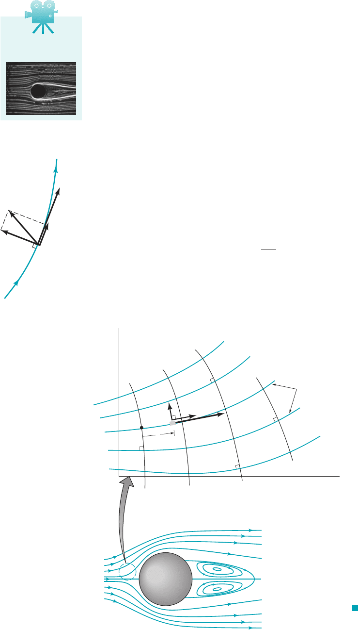
GIVEN An incompressible, inviscid fluid flows steadily past a
ball of radius R, as shown in Fig. E4.4a. According to a more ad-
vanced analysis of the flow, the fluid velocity along streamline
A–B is given by
where is the upstream velocity far ahead of the sphere.
FIND Determine the acceleration experienced by fluid parti-
cles as they flow along this streamline.
V
0
V u1x2i
ˆ
V
0
a1
R
3
x
3
b i
ˆ
S
OLUTION
Acceleration along a Streamline
E
XAMPLE 4.4
A
x
y
V
0
V
V
(
a
)
B
A
B
(
b
)
–
0
.
2
–
0
.4
–
0
.
6
x
/
x
x
R
/
/
–
1
–
2
–
3
a
x
_______
(
V
0
V
V
2
/
R
/
/
)
F I G U R E E4.4
Along streamline A–B there is only one component of velocity
so that from Eq. 4.3
or
Since the flow is steady the velocity at a given point in space does
not change with time. Thus, With the given velocity dis-
tribution along the streamline, the acceleration becomes
or
(Ans)
COMMENTS Along streamline and
the acceleration has only an x component and it is negative
1a deceleration2. Thus, the fluid slows down from its upstream
y 02
A–B 1
q
x R
a
x
31V
0
2
R2
1 1R
x2
3
1x
R2
4
a
x
u
0u
0x
V
0
a1
R
3
x
3
b V
0
3R
3
13x
4
24
0u
0t 0.
a
x
0u
0t
u
0u
0x
,
a
y
0,
a
z
0
a
0V
0t
u
0V
0x
a
0u
0t
u
0u
0x
b i
ˆ
1v w 02
velocity of at to its stagnation point velocity of
at the “nose” of the ball. The variation of along
streamline is shown in Fig. E4.4b. It is the same result as is
obtained in Example 3.1 by using the streamwise component of
the acceleration, The maximum deceleration occurs
at and has a value of Note
that this maximum deceleration increases with increasing velocity
and decreasing size. As indicated in the following table, typical val-
ues of this deceleration can be quite large. For example, the
value for a pitched baseball is a decel-
eration approximately 1500 times that of gravity.
a
x,max
4.08 10
4
ft
s
2
a
x,max
0.610 V
0
2
R.x 1.205R
a
x
V 0V
0s.
A–B
a
x
x R,V 0
x
q
V V
0
i
ˆ
JWCL068_ch04_147-186.qxd 8/19/08 8:50 PM Page 158
4.2.2 Unsteady Effects
As is seen from Eq. 4.5, the material derivative formula contains two types of terms—those
involving the time derivative and those involving spatial derivatives
and The time derivative portions are denoted as the local derivative. They represent
effects of the unsteadiness of the flow. If the parameter involved is the acceleration, that portion
given by is termed the local acceleration. For steady flow the time derivative is zero
throughout the flow field and the local effect vanishes. Physically, there is no change
in flow parameters at a fixed point in space if the flow is steady. There may be a change of those
parameters for a fluid particle as it moves about, however.
If a flow is unsteady, its parameter values 1velocity, temperature, density, etc.2at any location
may change with time. For example, an unstirred cup of coffee will cool down in time
because of heat transfer to its surroundings. That is,
Similarly, a fluid particle may have nonzero acceleration as a result of the unsteady effect of the flow.
Consider flow in a constant diameter pipe as is shown in Fig. 4.5. The flow is assumed to be spatially
uniform throughout the pipe. That is, at all points in the pipe. The value of the acceleration
depends on whether is being increased, or decreased, Unless is
independent of time 1 constant2there will be an acceleration, the local acceleration term. Thus,
the acceleration field, is uniform throughout the entire flow, although it may vary with
time 1 need not be constant2. The acceleration due to the spatial variations of velocity 1
etc.2vanishes automatically for this flow, since and That is,
4.2.3 Convective Effects
The portion of the material derivative 1Eq. 4.52represented by the spatial derivatives is termed
the convective derivative. It represents the fact that a flow property associated with a fluid
particle may vary because of the motion of the particle from one point in space where the
parameter has one value to another point in space where its value is different. For example,
the water velocity at the inlet of the garden hose nozzle shown in the figure in the margin is
different (both in direction and speed) than it is at the exit. This contribution to the time rate
of change of the parameter for the particle can occur whether the flow is steady or unsteady.
a
0V
0t
u
0V
0x
v
0V
0y
w
0V
0z
0V
0t
0V
0
0t
i
ˆ
v w 0.0u
0x 00v
0y,
u 0u
0x, v0V
0
0t
a 0V
0
0t i
ˆ
,
V
0
⬅
V
0
0V
0
0t 6 0.0V
0
0t 7 0,V
0
V V
0
1t2 i
ˆ
DT
Dt 0T
0t V ⴢ §T 0T
0t 6 0.
1V 02
3012
0t ⬅ 04,
0V
0t
012
0z4.
012
0y,3012
0x,3012
0t4
4.2 The Acceleration Field 159
In general, for fluid particles on streamlines other than
all three components of the acceleration and will be
nonzero.
a
z
21a
x
, a
y
,
A–B,
Object
Rising weather
balloon 1 4.0
Soccer ball 20 0.80
Baseball 90 0.121
Tennis ball 100 0.104
Golf ball 200 0.070 3.49 10
5
5.87 10
4
4.08 10
4
305
0.153
a
x,max
1ft
s
2
2R 1ft2V
0
1ft
s2
The local derivative
is a result of the un-
steadiness of the
flow.
V4.12 Unsteady
flow
F I G U R E 4.5 Uniform, unsteady
flow in a constant diameter pipe.
V
0
(t)
V
0
(t)
x
V
2
> V
1
V
1
JWCL068_ch04_147-186.qxd 8/19/08 8:50 PM Page 159
It is due to the convection, or motion, of the particle through space in which there is a gradient
in the parameter value. That portion of the acceleration
given by the term is termed the convective acceleration.
As is illustrated in Fig. 4.6, the temperature of a water particle changes as it flows through
a water heater. The water entering the heater is always the same cold temperature and the water
leaving the heater is always the same hot temperature. The flow is steady. However, the temperature,
T, of each water particle increases as it passes through the heater— Thus,
because of the convective term in the total derivative of the temperature. That is, but
1where x is directed along the streamline2, since there is a nonzero temperature gradient
along the streamline. A fluid particle traveling along this nonconstant temperature path
at a specified speed 1u2will have its temperature change with time at a rate of
even though the flow is steady
The same types of processes are involved with fluid accelerations. Consider flow in a variable
area pipe as shown in Fig. 4.7. It is assumed that the flow is steady and one-dimensional with
velocity that increases and decreases in the flow direction as indicated. As the fluid flows from
section 112to section 122, its velocity increases from to Thus, even though 1steady
flow2
,
fluid particles experience an acceleration given by 1convective acceleration2.
For it is seen that so that —the fluid accelerates. For
it is seen that so that —the fluid decelerates. This acceleration and deceleration
are shown in the figure in the margin. If the amount of acceleration precisely balances
the amount of deceleration even though the distances between and and and are not the
same.
The concept of the material derivative can be used to determine the time rate of change of
any parameter associated with a particle as it moves about. Its use is not restricted to fluid mechanics
alone. The basic ingredients needed to use the material derivative concept are the field description
of the parameter, and the rate at which the particle moves through that field,
V V 1x, y, z, t2.
P P1x, y, z, t2,
x
2
x
3
x
1
x
2
V
1
V
3
,
a
x
6 00u
0x 6 0
x
2
6 x 6 x
3
,a
x
7 00u
0x 7 0x
1
6 x 6 x
2
,
a
x
u 0u
0x
0V
0t 0V
2
.V
1
10T
0t 02.
DT
Dt u 0T
0x
10T
0x 02
u 0T
0x 0
0T
0t 0,
DT
Dt 0T
out
7 T
in
.
1V ⴢ §2V
3§12 012
0x i
ˆ
012
0y j
ˆ
012
0z k
ˆ
4
160 Chapter 4 ■ Fluid Kinematics
F I G U R E 4.6 Steady-state
operation of a water heater. (Photo courtesy
of American Water Heater Company.)
Hot
T
out
> T
in
Water
heater
Pathline
= 0
T
___
t
∂
∂
≠ 0
DT
___
Dt
Cold
T
in
F I G U R E 4.7 Uniform, steady flow in a variable
area pipe.
x
u = V
3
= V
1
< V
2
x
3
x
2
x
1
u = V
2
> V
1
u = V
1
u
x
0
a
x
x
0
The convective de-
rivative is a result
of the spatial varia-
tion of the flow.
JWCL068_ch04_147-186.qxd 8/19/08 8:50 PM Page 160
4.2 The Acceleration Field 161
GIVEN Consider the steady, two-dimensional flow field dis-
cussed in Example 4.2.
Acceleration from a Given Velocity Field
FIND Determine the acceleration field for this flow.
E
XAMPLE 4.5
S
OLUTION
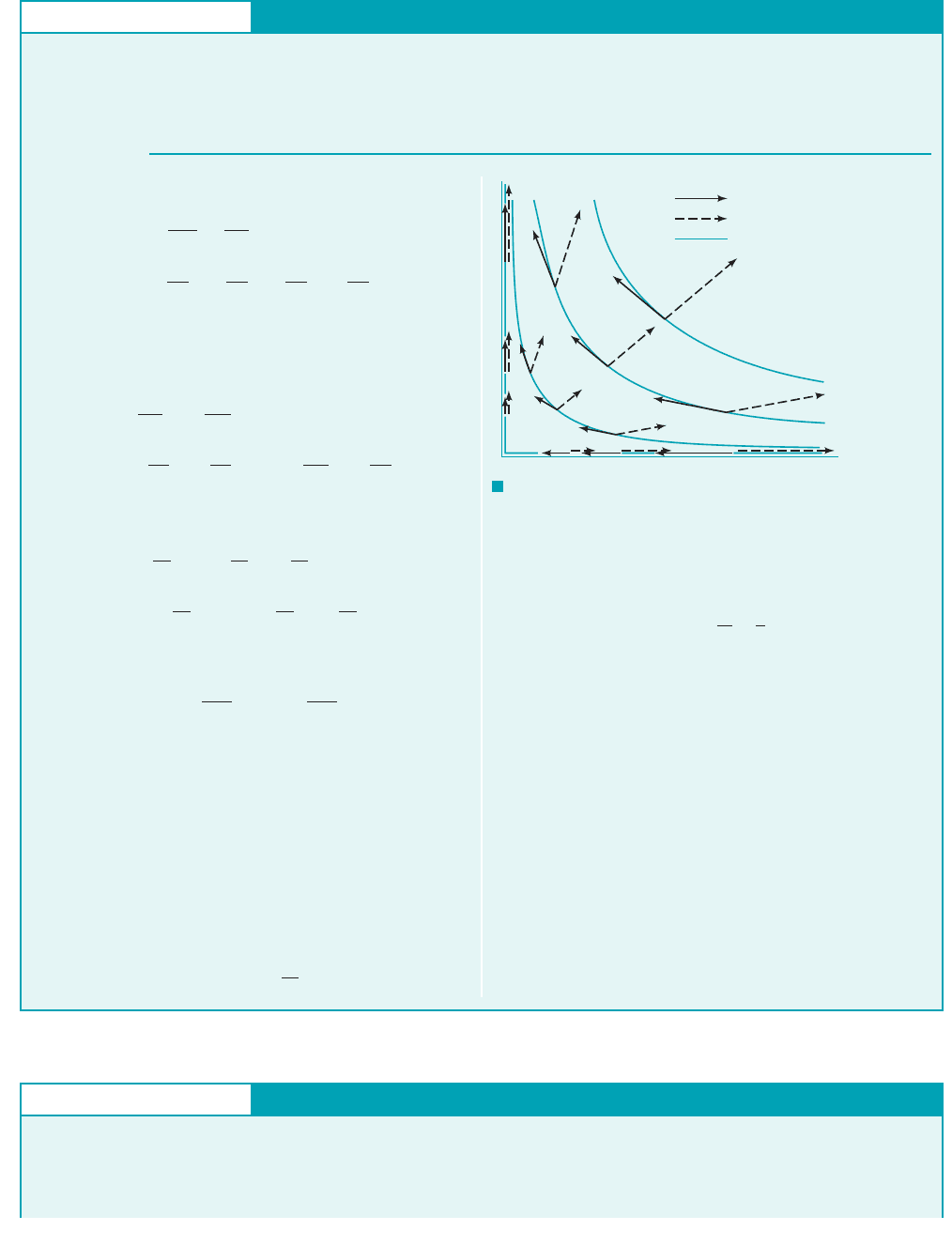
Also, the acceleration vector is oriented at an angle from the x
axis, where
This is the same angle as that formed by a ray from the origin to
point Thus, the acceleration is directed along rays from the
origin and has a magnitude proportional to the distance from the
origin. Typical acceleration vectors 1from Eq. 22and velocity vec-
tors 1from Example 4.12are shown in Fig. E4.5 for the flow in the
first quadrant. Note that a and V are not parallel except along the
x and y axes 1a fact that is responsible for the curved pathlines of
the flow2, and that both the acceleration and velocity are zero at
the origin An infinitesimal fluid particle placed pre-
cisely at the origin will remain there, but its neighbors 1no matter
how close they are to the origin2will drift away.
1x ⫽ y ⫽ 02.
1x, y2.
tan u ⫽
a
y
a
x
⫽
y
x
u
In general, the acceleration is given by
(1)
where the velocity is given by so that
and For steady two-
dimensional and flow, Eq. l becomes
Hence, for this flow the acceleration is given by
or
(Ans)
COMMENTS
The fluid experiences an acceleration in both
the x and y directions. Since the flow is steady, there is no local
acceleration—the fluid velocity at any given point is constant in
time. However, there is a convective acceleration due to the
change in velocity from one point on the particle’s pathline to an-
other. Recall that the velocity is a vector—it has both a magnitude
and a direction. In this flow both the fluid speed 1magnitude2and
flow direction change with location 1see Fig. E4.1a2.
For this flow the magnitude of the acceleration is constant on
circles centered at the origin, as is seen from the fact that
(2)0a0⫽ 1a
x
2
⫹ a
y
2
⫹ a
z
2
2
1
Ⲑ
2
⫽ a
V
0
/
b
2
1x
2
⫹ y
2
2
1
Ⲑ
2
a
x
⫽
V
2
0
x
/
2
,
a
y
⫽
V
2
0
y
/
2
⫹ ca⫺
V
0
/
b 1x2102⫹ a
V
0
/
b 1y2 a
V
0
/
bd j
ˆ
a ⫽ ca⫺
V
0
/
b 1x2 a⫺
V
0
/
b⫹ a
V
0
/
b 1y2102d i
ˆ
⫽ au
0u
0x
⫹ v
0u
0y
b i
ˆ
⫹ au
0v
0x
⫹ v
0v
0y
b j
ˆ
a ⫽ u
0V
0x
⫹ v
0V
0y
012
Ⲑ
0z ⫽ 043w ⫽ 0
3012
Ⲑ
0t ⫽ 04,v ⫽ 1V
0
Ⲑ
/2y.u ⫽⫺1V
0
Ⲑ
/2
x
V ⫽ 1V
0
Ⲑ
/21⫺xi
ˆ
⫹ yj
ˆ
2
⫽
0V
0t
⫹ u
0V
0x
⫹ v
0V
0y
⫹ w
0V
0z
a ⫽
DV
Dt
⫽
0V
0t
⫹ 1V ⴢ § 21V2
GIVEN A fluid flows steadily through a two-dimensional nozzle
of length as shown in Fig. E4.6a. The nozzle shape is given by
y
Ⲑ
/ ⫽ ; 0.5
Ⲑ
31 ⫹ 1x
Ⲑ
/24
/
The Material Derivative
If viscous and gravitational effects are negligible, the velocity
field is approximately
(1)u ⫽ V
0
冤1 ⫹ x
Ⲑ
/冥, v ⫽⫺V
0
y
Ⲑ
/
E
XAMPLE 4.6
F I G U R E E4.5
V
a
Streamline
y
x
JWCL068_ch04_147-186.qxd 8/19/08 8:50 PM Page 161
162 Chapter 4 ■ Fluid Kinematics
and the pressure field is
where V
0
and p
0
are the velocity and pressure at the origin,
. Note that the fluid speed increases as it flows through
the nozzle. For example, along the center line , at
and at .
FIND Determine, as a function of x and y, the time rate of
change of pressure felt by a fluid particle as it flows through the
nozzle.
x ⫽ /V ⫽ 2V
0
x ⫽ 0
V ⫽ V
0
1y ⫽ 02
x ⫽ y ⫽ 0
p ⫺ p
0
⫽⫺1rV
0
2
Ⲑ
2231x
2
⫹ y
2
2
Ⲑ
/
2
⫹ 2x
Ⲑ
/4
S
OLUTION
F I G U R E E4.6
a
COMMENT Lines of constant pressure within the nozzle are
indicated in Fig. E4.6b, along with some representative stream-
lines of the flow. Note that as a fluid particle flows along its
streamline, it moves into areas of lower and lower pressure.
Hence, even though the flow is steady, the time rate of change of
the pressure for any given particle is negative. This can be verified
from Eq. (5) which, when plotted in Fig. E4.6c, shows that for any
point within the nozzle .Dp
Ⲑ
Dt 6 0
The time rate of change of pressure at any given, fixed point in
this steady flow is zero. However, the time rate of change of pres-
sure felt by a particle flowing through the nozzle is given by the
material derivative of the pressure and is not zero. Thus,
(2)
where the x- and y-components of the pressure gradient can be
written as
(3)
and
(4)
Therefore, by combining Eqs. (1), (2), (3), and (4) we obtain
or
(5)
(Ans)
Dp
Dt
⫽⫺
rV
0
3
/
ca
x
/
⫹ 1b
2
⫺ a
y
/
b
2
d
Dp
Dt
⫽ V
0
a1 ⫹
x
/
b a⫺
rV
0
2
/
b a
x
/
⫹ 1b⫹ a⫺V
0
y
/
b a⫺
rV
0
2
/
b a
y
/
b
0p
0y
⫽⫺
rV
0
2
/
a
y
/
b
0p
0x
⫽⫺
rV
0
2
/
a
x
/
⫹ 1b
Dp
Dt
⫽
0p
0t
⫹ u
0p
0x
⫹ v
0p
0y
⫽ u
0p
0x
⫹ v
0p
0y
y
ᐉ
x
V
0
2V
0
0
0.5
_______
(1 + x/ᐉ)
y
_
ᐉ
=
y
_
ᐉ
= –
0.5
_______
(1 + x/ᐉ)
0
1
0.5
–0.5
–1.0
–1.5
–2.0
–3.0
–2.5
y
_
ᐉ
p
–
p
0
______
1
/
2
r
V
0
2
x
_
ᐉ
F I G U R E E4.6
b
–0.5
0.5
–1
–2.25
–4
= 0
x
_
ᐉ
= 0.5
x
_
ᐉ
x
_
ᐉ
y
_
ᐉ
= 1
x
_
ᐉ
Dp/Dt
_______
(
ρ
V
0
3
/ᐉ)
F I G U R E E4.6
c
JWCL068_ch04_147-186.qxd 8/19/08 8:50 PM Page 162
4.2.4 Streamline Coordinates
In many flow situations it is convenient to use a coordinate system defined in terms of the streamlines
of the flow. An example for steady, two-dimensional flows is illustrated in Fig. 4.8. Such flows
can be described either in terms of the usual x, y Cartesian coordinate system 1or some other system
such as the r, polar coordinate system2or the streamline coordinate system. In the streamline
coordinate system the flow is described in terms of one coordinate along the streamlines, denoted
s, and the second coordinate normal to the streamlines, denoted n. Unit vectors in these two
directions are denoted by and as shown in the figure. Care is needed not to confuse the coordinate
distance s 1a scalar2with the unit vector along the streamline direction,
The flow plane is therefore covered by an orthogonal curved net of coordinate lines. At any
point the s and n directions are perpendicular, but the lines of constant s or constant n are not
necessarily straight. Without knowing the actual velocity field 1hence, the streamlines2it is not
possible to construct this flow net. In many situations appropriate simplifying assumptions can be
made so that this lack of information does not present an insurmountable difficulty. One of the major
advantages of using the streamline coordinate system is that the velocity is always tangent to the s
direction. That is,
This allows simplifications in describing the fluid particle acceleration and in solving the equations
governing the flow.
For steady, two-dimensional flow we can determine the acceleration as
where and are the streamline and normal components of acceleration, respectively, as indicated
by the figure in the margin. We use the material derivative because by definition the acceleration
is the time rate of change of the velocity of a given particle as it moves about. If the streamlines
a
n
a
s
a ⫽
DV
Dt
⫽ a
s
sˆ ⫹ a
n
nˆ
V ⫽ V sˆ
sˆ.
nˆ,sˆ
u
4.2 The Acceleration Field 163
V4.13 Streamline
coordinates
F I G U R E 4.8
Streamline coordinate system
for two-dimensional flow.
s
n
^
s
^
V
s = 0
s = s
1
s = s
2
n = n
2
n = n
1
n = 0
Streamlines
y
x
V
a
a
s
a
n
JWCL068_ch04_147-186.qxd 8/19/08 8:51 PM Page 163
are curved, both the speed of the particle and its direction of flow may change from one point to
another. In general, for steady flow both the speed and the flow direction are a function of location—
and For a given particle, the value of s changes with time, but the value
of n remains fixed because the particle flows along a streamline defined by constant. 1Recall
that streamlines and pathlines coincide in steady flow.2Thus, application of the chain rule gives
or
This can be simplified by using the fact that for steady flow nothing changes with time at a given
point so that both and are zero. Also, the velocity along the streamline is and
the particle remains on its streamline 1 constant2so that Hence,
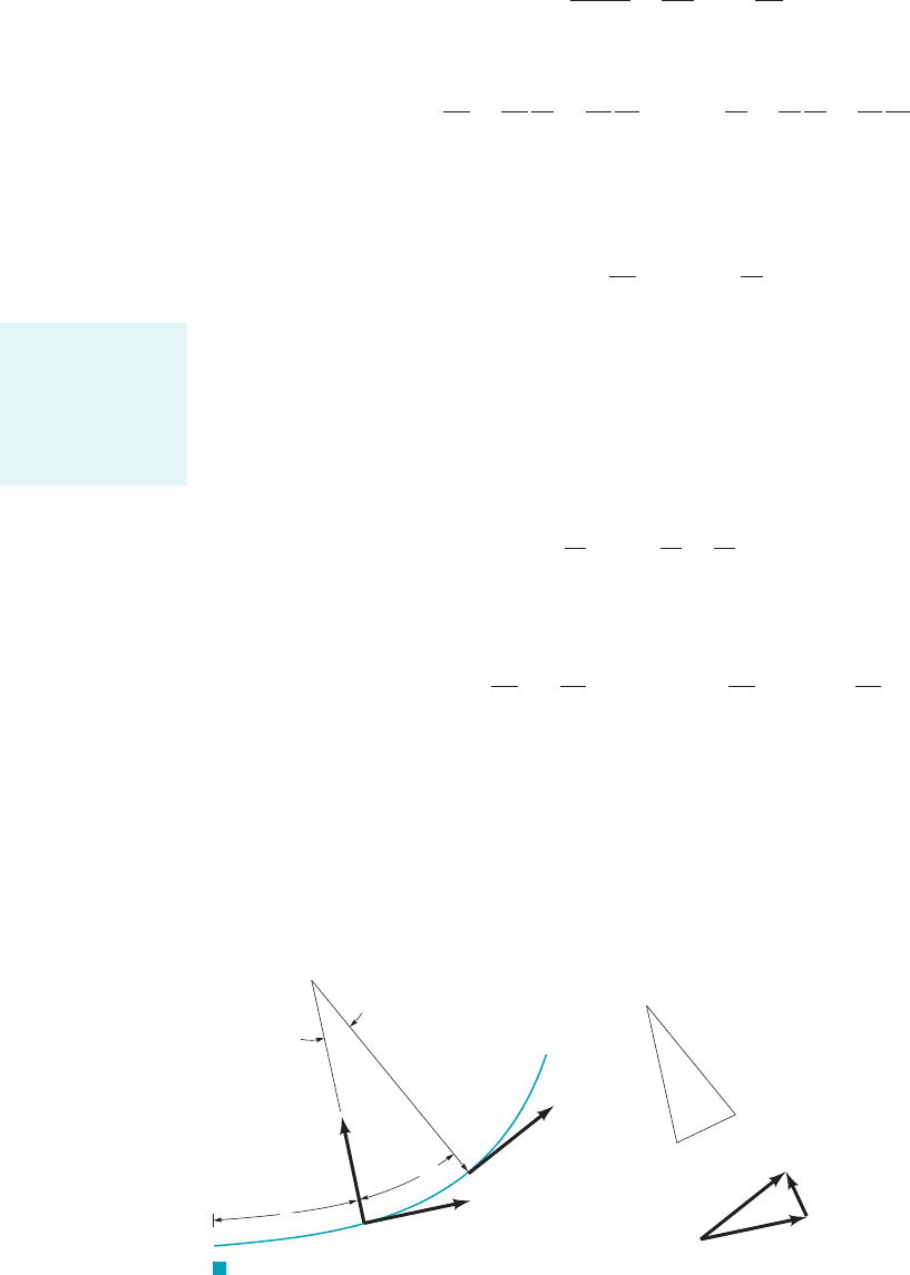
The quantity represents the limit as of the change in the unit vector along the
streamline, per change in distance along the streamline, The magnitude of is constant
1 it is a unit vector2, but its direction is variable if the streamlines are curved. From Fig. 4.9
it is seen that the magnitude of is equal to the inverse of the radius of curvature of the
streamline, at the point in question. This follows because the two triangles shown 1AOB and
2are similar triangles so that or Similarly, in the
limit the direction of is seen to be normal to the streamline. That is,
Hence, the acceleration for steady, two-dimensional flow can be written in terms of its streamwise
and normal components in the form
(4.7)
The first term, represents the convective acceleration along the streamline and the
second term, represents centrifugal acceleration 1one type of convective acceleration2
normal to the fluid motion. These components can be noted in Fig. E4.5 by resolving the
acceleration vector into its components along and normal to the velocity vector. Note that the unit
vector is directed from the streamline toward the center of curvature. These forms of the
acceleration were used in Chapter 3 and are probably familiar from previous dynamics or physics
considerations.
nˆ
a
n
⫽ V
2
Ⲑ
r,
a
s
⫽ V 0V
Ⲑ
0s,
a ⫽ V
0V
0s
sˆ ⫹
V
2
r
nˆ
or
a
s
⫽ V
0V
0s
,
a
n
⫽
V
2
r
0sˆ
0s
⫽ lim
dsS0
dsˆ
ds
⫽
nˆ
r
dsˆ
Ⲑ
dsds S 0,
0dsˆ
Ⲑ
ds0⫽ 1
Ⲑ
r.ds
Ⲑ
r ⫽ 0d sˆ0
Ⲑ
0sˆ 0⫽ 0dsˆ0,A¿O¿B¿
r,
0sˆ
Ⲑ
0s
0sˆ0⫽ 1;
sˆds.dsˆ,
ds S 00sˆ
Ⲑ
0s
a ⫽ aV
0V
0s
b sˆ ⫹ V aV
0sˆ
0s
b
dn
Ⲑ
dt ⫽ 0.n ⫽
V ⫽ ds
Ⲑ
dt0sˆ
Ⲑ
0t0V
Ⲑ
0t
a ⫽ a
0V
0t
⫹
0V
0s
ds
dt
⫹
0V
0n
dn
dt
b
sˆ ⫹ V a
0sˆ
0t
⫹
0sˆ
0s
ds
dt
⫹
0sˆ
0n
dn
dt
b
a ⫽
D1V sˆ2
Dt
⫽
DV
Dt
sˆ ⫹ V
Dsˆ
Dt
n ⫽
sˆ ⫽ sˆ1s, n2.V ⫽ V1s, n2
164 Chapter 4 ■ Fluid Kinematics
F I G U R E 4.9 Relationship between the unit vector along the
streamline, and the radius of curvature of the streamline, .rs
ˆ
,
O
O
O'
δθ
δθ
δθ
s
s
A
A
A
'
B
B
B'
δ
s
δ
δ
n
^
s
^
s(
s
)
^
s(
s
)
^
s(
s
+
s
)
^
δ
s(
s
+
s
)
^
δ
The orientation of
the unit vector
along the stream-
line changes with
distance along the
streamline.
JWCL068_ch04_147-186.qxd 8/19/08 8:51 PM Page 164

4.3 Control Volume and System Representations 165
As is discussed in Chapter 1, a fluid is a type of matter that is relatively free to move and
interact with its surroundings. As with any matter, a fluid’s behavior is governed by fundamental
physical laws which are approximated by an appropriate set of equations. The application of laws
such as the conservation of mass, Newton’s laws of motion, and the laws of thermodynamics form
the foundation of fluid mechanics analyses. There are various ways that these governing laws can
be applied to a fluid, including the system approach and the control volume approach. By definition,
a system is a collection of matter of fixed identity 1always the same atoms or fluid particles2, which
may move, flow, and interact with its surroundings. A control volume, on the other hand, is a
volume in space 1a geometric entity, independent of mass2through which fluid may flow.
A system is a specific, identifiable quantity of matter. It may consist of a relatively large
amount of mass 1such as all of the air in the earth’s atmosphere2, or it may be an infinitesimal size
1such as a single fluid particle2. In any case, the molecules making up the system are “tagged” in
some fashion 1dyed red, either actually or only in your mind2so that they can be continually
identified as they move about. The system may interact with its surroundings by various means 1by
the transfer of heat or the exertion of a pressure force, for example2. It may continually change size
and shape, but it always contains the same mass.
A mass of air drawn into an air compressor can be considered as a system. It changes shape
and size 1it is compressed2, its temperature may change, and it is eventually expelled through the
outlet of the compressor. The matter associated with the original air drawn into the compressor
remains as a system, however. The behavior of this material could be investigated by applying the
appropriate governing equations to this system.
One of the important concepts used in the study of statics and dynamics is that of the free-
body diagram. That is, we identify an object, isolate it from its surroundings, replace its surroundings
by the equivalent actions that they put on the object, and apply Newton’s laws of motion. The body
in such cases is our system—an identified portion of matter that we follow during its interactions
with its surroundings. In fluid mechanics, it is often quite difficult to identify and keep track of a
specific quantity of matter. A finite portion of a fluid contains an uncountable number of fluid
particles that move about quite freely, unlike a solid that may deform but usually remains relatively
easy to identify. For example, we cannot as easily follow a specific portion of water flowing in a
river as we can follow a branch floating on its surface.
We may often be more interested in determining the forces put on a fan, airplane, or
automobile by air flowing past the object than we are in the information obtained by following a
given portion of the air 1a system2as it flows along. Similarly, for the Space Shuttle launch vehicle
shown in the margin, we may be more interested in determining the thrust produced than we are in
the information obtained by following the highly complex, irregular path of the exhaust plume from
the rocket engine nozzle. For these situations we often use the control volume approach. We identify
a specific volume in space 1a volume associated with the fan, airplane, or automobile, for example2
and analyze the fluid flow within, through, or around that volume. In general, the control volume
can be a moving volume, although for most situations considered in this book we will use only
fixed, nondeformable control volumes. The matter within a control volume may change with time
as the fluid flows through it. Similarly, the amount of mass within the volume may change with
time. The control volume itself is a specific geometric entity, independent of the flowing fluid.
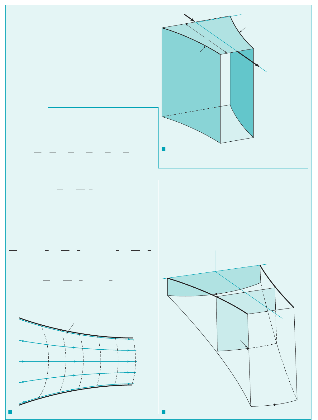
Examples of control volumes and control surfaces 1the surface of the control volume2are
shown in Fig. 4.10. For case 1a2, fluid flows through a pipe. The fixed control surface consists of
the inside surface of the pipe, the outlet end at section 122, and a section across the pipe at 112. One
portion of the control surface is a physical surface 1the pipe2, while the remainder is simply a surface
in space 1across the pipe2. Fluid flows across part of the control surface, but not across all of it.
Another control volume is the rectangular volume surrounding the jet engine shown in Fig.
4.10b. If the airplane to which the engine is attached is sitting still on the runway, air flows through
this control volume because of the action of the engine within it. The air that was within the engine
itself at time 1a system2has passed through the engine and is outside of the control volume
at a later time as indicated. At this later time other air 1a different system2is within the engine.
If the airplane is moving, the control volume is fixed relative to an observer on the airplane, but it
t ⫽ t
2
t ⫽ t
1
4.3 Control Volume and System Representations
Both control vol-
ume and system
concepts can be
used to describe
fluid flow.
(Photograph courtesy
of NASA.)
JWCL068_ch04_147-186.qxd 8/19/08 8:51 PM Page 165
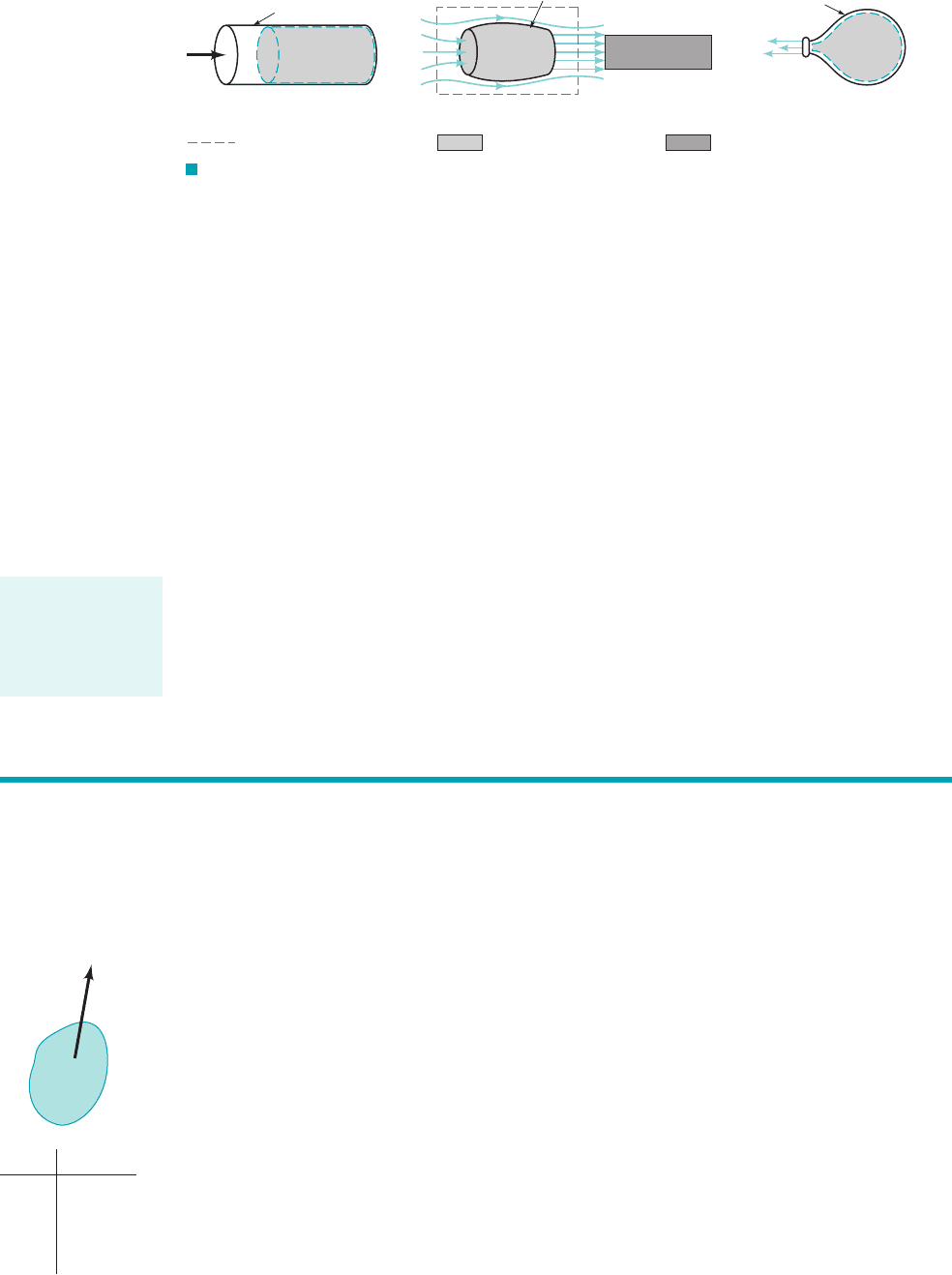
is a moving control volume relative to an observer on the ground. In either situation air flows
through and around the engine as indicated.
The deflating balloon shown in Fig. 4.10c provides an example of a deforming control volume.
As time increases, the control volume 1whose surface is the inner surface of the balloon2decreases
in size. If we do not hold onto the balloon, it becomes a moving, deforming control volume as it
darts about the room. The majority of the problems we will analyze can be solved by using a fixed,
nondeforming control volume. In some instances, however, it will be advantageous, in fact
necessary, to use a moving, deforming control volume.
In many ways the relationship between a system and a control volume is similar to the relationship
between the Lagrangian and Eulerian flow description introduced in Section 4.1.1. In the system or
Lagrangian description, we follow the fluid and observe its behavior as it moves about. In the control
volume or Eulerian description we remain stationary and observe the fluid’s behavior at a fixed location.
1If a moving control volume is used, it virtually never moves with the system—the system flows
through the control volume.2These ideas are discussed in more detail in the next section.
All of the laws governing the motion of a fluid are stated in their basic form in terms of a
system approach. For example, “the mass of a system remains constant,” or “the time rate of change
of momentum of a system is equal to the sum of all the forces acting on the system.” Note the word
system, not control volume, in these statements. To use the governing equations in a control volume
approach to problem solving, we must rephrase the laws in an appropriate manner. To this end we
introduce the Reynolds transport theorem in the following section.
166 Chapter 4 ■ Fluid Kinematics
F I G U R E 4.10 Typical control volumes: (a) fixed control volume, (b) fixed or moving
control volume, (c) deforming control volume.
V
Pipe
(1) (2)
(a) (b)
Jet engine
(c)
Balloon
Control volume surface System at time t
1
System at time t
2
> t
1
We are sometimes interested in what happens to a particular part of the fluid as it moves about.
Other times we may be interested in what effect the fluid has on a particular object or volume in
space as fluid interacts with it. Thus, we need to describe the laws governing fluid motion using
both system concepts 1consider a given mass of the fluid2and control volume concepts 1consider
a given volume2. To do this we need an analytical tool to shift from one representation to the other.
The Reynolds transport theorem provides this tool.
All physical laws are stated in terms of various physical parameters. Velocity, acceleration, mass,
temperature, and momentum are but a few of the more common parameters. Let B represent any of
these 1or other2fluid parameters and b represent the amount of that parameter per unit mass. That is,
where m is the mass of the portion of fluid of interest. For example, as shown by the figure in the
margin, if the mass, it follows that The mass per unit mass is unity. If
the kinetic energy of the mass, then the kinetic energy per unit mass. The parameters B
and b may be scalars or vectors. Thus, if the momentum of the mass, then 1The
momentum per unit mass is the velocity.2
The parameter B is termed an extensive property and the parameter b is termed an intensive
property. The value of B is directly proportional to the amount of the mass being considered,
whereas the value of b is independent of the amount of mass. The amount of an extensive property
that a system possesses at a given instant, can be determined by adding up the amount associated
with each fluid particle in the system. For infinitesimal fluid particles of size and mass r dV⫺,d V⫺
B
sys
,
b ⫽ V.B ⫽ mV,
b ⫽ V
2
Ⲑ
2,
B ⫽ mV
2
Ⲑ
2,b ⫽ 1.B ⫽ m,
B ⫽ mb
4.4 The Reynolds Transport Theorem
The governing laws
of fluid motion are
stated in terms of
fluid systems, not
control volumes.
V
m
V
Bb = B/m
1m
m
V
1_
2
mV
2
1_
2
1_
2
V
2
1_
2
JWCL068_ch04_147-186.qxd 8/19/08 8:51 PM Page 166