Munson B.R. Fundamentals of Fluid Mechanics
Подождите немного. Документ загружается.

2. We confine ourselves to steady or steady-in-the-mean cyclical flows. Thus,
at any instant of time for steady flows or on a time-average basis for cyclical unsteady
flows.
3. We work only with the component of Eq. 5.42 resolved along the axis of rotation.
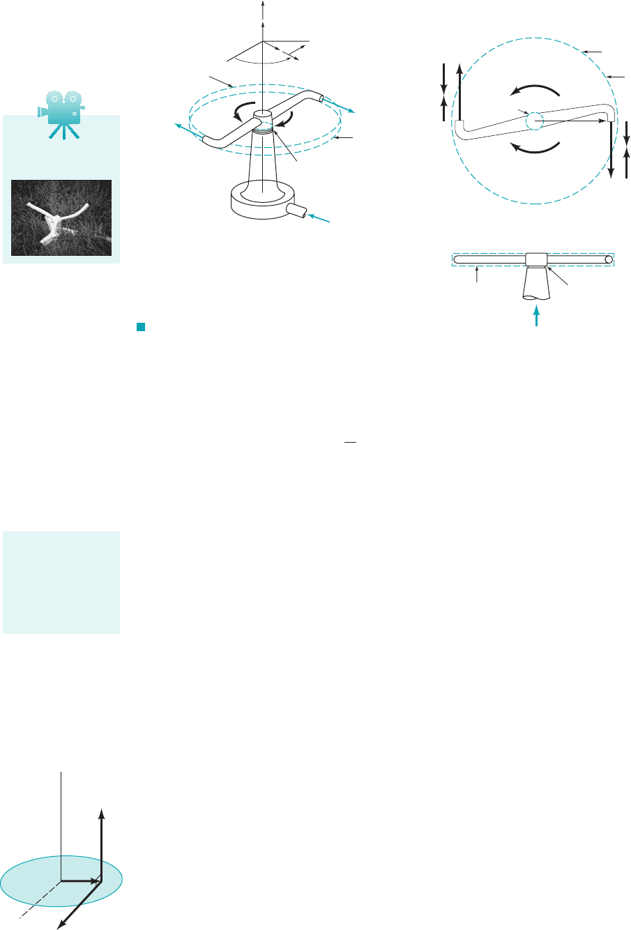
Consider the rotating sprinkler sketched in Fig. 5.4. Because the direction and magnitude of the flow
through the sprinkler from the inlet [section 112] to the outlet [section 122] of the arm changes, the
water exerts a torque on the sprinkler head causing it to tend to rotate or to actually rotate in the di-
rection shown, much like a turbine rotor. In applying the moment-of-momentum equation 1Eq. 5.422
to this flow situation, we elect to use the fixed and nondeforming control volume shown in Fig. 5.4.
This disk-shaped control volume contains within its boundaries the spinning or stationary sprinkler
head and the portion of the water flowing through the sprinkler contained in the control volume at
an instant. The control surface cuts through the sprinkler head’s solid material so that the shaft torque
that resists motion can be clearly identified. When the sprinkler is rotating, the flow field in the sta-
tionary control volume is cyclical and unsteady, but steady in the mean. We proceed to use the ax-
ial component of the moment-of-momentum equation 1Eq. 5.422to analyze this flow.
The integrand of the moment-of-momentum flow term in Eq. 5.42,
can be nonzero only where fluid is crossing the control surface. Everywhere else on the control
surface this term will be zero because Water enters the control volume axially through
the hollow stem of the sprinkler at section 112. At this portion of the control surface, the compo-
nent of resolved along the axis of rotation is zero because as illustrated by the figure in the
margin, lies in the plane of section (1), perpendicular to the axis of rotation. Thus, there is
no axial moment-of-momentum flow in at section 112. Water leaves the control volume through
each of the two nozzle openings at section 122. For the exiting flow, the magnitude of the axial
component of is where is the radius from the axis of rotation to the nozzle centerline
and is the value of the tangential component of the velocity of the flow exiting each nozzle asV
u2
r
2
r
2
V
u2
,r ⴛ V
r ⴛ V
r ⴛ V
V ⴢ nˆ ⫽ 0.
冮
cs
1r ⴛ V2rV ⴢ nˆ dA
0
0t
冮
cv
1r ⴛ V2r dV⫺⫽0
5.2 Newton’s Second Law—The Linear Momentum and Moment-of-Momentum Equations 217
Change in moment
of fluid velocity
around an axis can
result in torque and
rotation around
that same axis.
F I G U R E 5.4 (a) Rotary water
sprinkler. (b) Rotary water sprinkler, plane view.
(c) Rotary water sprinkler, side view.
Control volume
Flow out
Section (1)
Section (2)
Flow out
Flow in
T
shaft
ω
(a)
z
r
θ
e
θ
Control volume
Section (2)
Section (1)
T
shaft
(b)
W
2
U
2
V
2
W
2
U
2
= r
2
ω
ω
r
2
V
2
Flow
Control volume
(
c)
Section (1)
^
e
z
^
^
e
r
θ
V5.10 Rotating
lawn sprinkler
z
r
r × V
V
(1)
JWCL068_ch05_187-262.qxd 9/23/08 10:00 AM Page 217

observed from a frame of reference attached to the fixed and nondeforming control volume. The
fluid velocity measured relative to a fixed control surface is an absolute velocity, V. The velocity
of the nozzle exit flow as viewed from the nozzle is called the relative velocity, W. The absolute
and relative velocities, V and W, are related by the vector relationship
(5.43)
where U is the velocity of the moving nozzle as measured relative to the fixed control surface.
The cross product and the dot product involved in the moment-of-momentum flow term of
Eq. 5.42,
can each result in a positive or negative value. For flow into the control volume, is negative.
For flow out, is positive. The correct algebraic sign to assign the axis component of
can be ascertained by using the right-hand rule. The positive direction along the axis of rotation is
the direction the thumb of the right hand points when it is extended and the remaining fingers are
curled around the rotation axis in the positive direction of rotation as illustrated in Fig. 5.5. The di-
rection of the axial component of is similarly ascertained by noting the direction of the cross
product of the radius from the axis of rotation, and the tangential component of absolute ve-
locity, Thus, for the sprinkler of Fig. 5.4, we can state that
(5.44)
where, because of mass conservation, is the total mass flowrate through both nozzles. As was
demonstrated in Example 5.7, the mass flowrate is the same whether the sprinkler rotates or not. The
correct algebraic sign of the axial component of can be easily remembered in the following
way: if and U are in the same direction, use and U are in opposite directions, use
The torque term of the moment-of-momentum equation 1Eq.
5.422is analyzed next. Confining ourselves to torques acting with respect to the axis of rotation
only, we conclude that the shaft torque is important. The net torque with respect to the axis of ro-
tation associated with normal forces exerted on the contents of the control volume will be very
small if not zero. The net axial torque due to fluid tangential forces is also negligibly small for the
control volume of Fig. 5.4. Thus, for the sprinkler of Fig. 5.4
(5.45)
Note that we have entered as a positive quantity in Eq. 5.45. This is equivalent to assuming
that is in the same direction as rotation.
For the sprinkler of Fig. 5.4, the axial component of the moment-of-momentum equation 1Eq.
5.422is, from Eqs. 5.44 and 5.45
(5.46)
We interpret being a negative quantity from Eq. 5.46 to mean that the shaft torque actually
opposes the rotation of the sprinkler arms as shown in Fig. 5.4. The shaft torque, opposes
rotation in all turbine devices.
T
shaft
,
T
shaft
⫺r
2
V
u2
m
#
⫽ T
shaft
T
shaft
T
shaft
a
B1r ⴛ F2
contents of the
control volume
R
axial
⫽ T
shaft
3g 1r ⴛ F2
contents of the control volume
4
⫺.⫹; if V
u
V
u
r ⴛ V
m
#
c
冮
cs
1r ⴛ V2rV ⴢ nˆ dAd
axial
⫽ 1⫺r
2
V
u2
21⫹m
#
2
V
u
ê
u
.
rê
r
,
r ⴛ V
r ⴛ VV ⴢ nˆ
V ⴢ nˆ
冮
cs
1r ⴛ V2rV ⴢ nˆ dA
V ⫽ W ⫹ U
218 Chapter 5 ■ Finite Control Volume Analysis
F I G U R E 5.5 Right-hand rule convention.
The algebraic sign
of r ⴛ V is obtained
by the right-hand
rule.
+
JWCL068_ch05_187-262.qxd 9/23/08 10:00 AM Page 218
We could evaluate the shaft power, associated with shaft torque, , by forming the
product of and the rotational speed of the shaft, [We use the notation that
Thus, from Eq. 5.46 we get
(5.47)
Since is the speed of each sprinkler nozzle, U, we can also state Eq. 5.47 in the form
(5.48)
Shaft work per unit mass, is equal to Dividing Eq. 5.48 by the mass flowrate,
we obtain
(5.49)
Negative shaft work as in Eqs. 5.47, 5.48, and 5.49 is work out of the control volume, that is, work
done by the fluid on the rotor and thus its shaft.
The principles associated with this sprinkler example can be extended to handle most sim-
plified turbomachine flows. The fundamental technique is not difficult. However, the geometry of
some turbomachine flows is quite complicated.
Example 5.18 further illustrates how the axial component of the moment-of-momentum equa-
tion 1Eq. 5.462can be used.
w
shaft
⫽⫺U
2
V
u2
m
#
,W
#
shaft
Ⲑ
m
#
.w
shaft
,
W
#
shaft
⫽⫺U
2
V
u2
m
#
r
2
v
W
#
shaft
⫽ T
shaft
v ⫽⫺r
2
V
u2
m
#
v
W ⫽ work, 1
#
2⫽ d12
Ⲑ
dt, and thus W
#
⫽ power.4
v.T
shaft
T
shaft
W
#
shaft
,
5.2 Newton’s Second Law—The Linear Momentum and Moment-of-Momentum Equations 219
Power is equal to
angular velocity
times torque.
V5.11 Impulse-type
lawn sprinkler
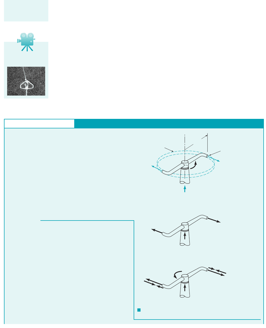
GIVEN Water enters a rotating lawn sprinkler through its base
at the steady rate of 1000 ml/s as sketched in Fig. E5.18a. The exit
area of each of the two nozzles is 30 mm
2
and the flow leaving each
nozzle is in the tangential direction. The radius from the axis of ro-
tation to the centerline of each nozzle is 200 mm.
FIND (a) Determine the resisting torque required to hold the
sprinkler head stationary.
(b) Determine the resisting torque associated with the sprinkler
rotating with a constant speed of 500 rev/min.
(c) Determine the speed of the sprinkler if no resisting torque is
applied.
S
OLUTION
F I G U R E E5.18
Moment-of-Momentum—Torque
Control volume
Flow out
Flow out
T
shaft
Q = 1000 ml/s
r
2
=
200 mm
Nozzle exit
area = 30 mm
2
(a)
(
b)
V
2
V
2
= V
2
θ
V
1
(c)
W
2
W
2
V
1
U
2
V
2
ω
V
2
= V
2
θ
U
2
= r
2
ω
E
XAMPLE 5.18
To solve parts (a), (b), and (c) of this example we can use the
same fixed and nondeforming, disk-shaped control volume illus-
trated in Fig. 5.4. As indicated in Fig. E5.18a, the only axial
torque considered is the one resisting motion, T
shaft
.
(a) When the sprinkler head is held stationary as specified in part
(a) of this example problem, the velocities of the fluid entering and
leaving the control volume are shown in Fig. E5.18b. Equation
5.46 applies to the contents of this control volume. Thus,
(1)
Since the control volume is fixed and nondeforming and the flow
exiting from each nozzle is tangential,
(2)
Equations 1 and 2 give
(3)T
shaft
⫽⫺r
2
V
2
m
#
V
2
⫽ V
2
T
shaft
⫽⫺r
2
V
2
m
#
JWCL068_ch05_187-262.qxd 9/23/08 10:01 AM Page 219

When the moment-of-momentum equation 1Eq. 5.422is applied to a more general, one-
dimensional flow through a rotating machine, we obtain
(5.50)T
shaft
1m
#
in
21r
in
V
uin
2 m
#
out
1r
out
V
uout
2
220 Chapter 5 ■ Finite Control Volume Analysis
In Example 5.7, we ascertained that V
2
16.7 m/s. Thus, from
Eq. 3 with
we obtain
or
(Ans)
(b) When the sprinkler is rotating at a constant speed of 500
rpm, the flow field in the control volume is unsteady but cyclical.
Thus, the flow field is steady in the mean. The velocities of the flow
entering and leaving the control volume are as indicated in Fig.
E5.18c. The absolute velocity of the fluid leaving each nozzle, V
2
,
is from Eq. 5.43,
(4)
where
as determined in Example 5.7. The speed of the nozzle, U
2
, is ob-
tained from
(5)
Application of the axial component of the moment-of-momentum
equation (Eq. 5.46) leads again to Eq. 3. From Eqs. 4 and 5,
or
Thus, using Eq. 3, with (as calculated previ-
ously), we get
or
(Ans)
COMMENT Note that the resisting torque associated with
sprinkler head rotation is much less than the resisting torque that
is required to hold the sprinkler stationary.
T
shaft
1.24 N ⴢ m
T
shaft
1200 mm216.2 m/s2 0.999 kg/s 31
1N/kg2/1m/s
2
24
11000 mm/m2
m
#
0.999 kg/s
V
2
16.7 m/s 10.5 m/s 6.2 m/s
16.7 m/s
1200 mm21500 rev/min212 rad/rev2
11000 mm/m2160 s/min2
V
2
16.7 m/s r
2
U
2
r
2
W
2
16.7 m/s
V
2
W
2
U
2
T
shaft
3.34 N ⴢ m
T
shaft
1200 mm2116.7 m/s210.999 kg/s231
1N/kg2/1m/s
2
24
11000 mm/m2
0.999 kg/s
m
#
Q
11000 ml/s2110
3
m
3
/liter21999 kg/m
3
2
11000 ml/liter2
(c) When no resisting torque is applied to the rotating sprinkler
head, a maximum constant speed of rotation will occur as demon-
strated below. Application of Eqs. 3, 4, and 5 to the contents of the
control volume results in
(6)
For no resisting torque, Eq. 6 yields
Thus,
(7)
In Example 5.4, we learned that the relative velocity of the
fluid leaving each nozzle, W
2
, is the same regardless of the speed
of rotation of the sprinkler head, , as long as the mass flowrate
of the fluid, , remains constant. Thus, by using Eq. 7 we obtain
or
(Ans)
For this condition (T
shaft
0), the water both enters and leaves the
control volume with zero angular momentum.
COMMENT Note that forcing a change in direction of a
flowing fluid, in this case with a sprinkler, resulted in rotary mo-
tion and a useful “sprinkling” of water over an area.
By repeating the calculations for various values of the angular
velocity, , the results shown in Fig. E5.18d are obtained. It is seen
that the magnitude of the resisting torque associated with rotation is
less than the torque required to hold the rotor stationary. Even in the
absence of a resisting torque, the rotor maximum speed is finite.
v
183.5 rad/s2160 s/min2
2 rad/rev
797 rpm
W
2
r
2
116.7 m/s211000 mm/m2
1200 mm2
83.5 rad/s
m
#
W
2
r
2
0 r
2
1W
2
r
2
2m
#
T
shaft
r
2
1W
2
r
2
2m
#
T
Shaft
,
N
.
m
–0.5
0
–1
–1.5
–2
–2.5
–3
–3.5
–4
ω,
rpm
200 400 6000 800
F I G U R E E5.18
d
JWCL068_ch05_187-262.qxd 9/23/08 10:01 AM Page 220

by applying the same kind of analysis used with the sprinkler of Fig. 5.4. The is used with
mass flowrate into the control volume, and the is used with mass flowrate out of the
control volume, to account for the sign of the dot product, involved. Whether
is used with the product depends on the direction of A simple way to
determine the sign of the product is to compare the direction of and the blade speed, U. As
shown in the margin, if and U are in the same direction, then the product is positive. If
and U are in opposite directions, the product is negative. The sign of the shaft torque is
is in the same direction along the axis of rotation as , and otherwise.
The shaft power, is related to shaft torque, by
(5.51)
Thus, using Eqs. 5.50 and 5.51 with a sign for in Eq. 5.50, we obtain
(5.52)
or since
(5.53)
The is used for the product when U and are in the same direction; the
is used when U and are in opposite directions. Also, since was used to obtain Eq. 5.53,
when is positive, power is into the fluid 1for example, a pump2, and when is negative,
power is out of the fluid 1for example, a turbine2.
The shaft work per unit mass, can be obtained from the shaft power, by divid-
ing Eq. 5.53 by the mass flowrate, By conservation of mass,
From Eq. 5.53, we obtain
(5.54)
The application of Eqs. 5.50, 5.53, and 5.54 is demonstrated in Example 5.19. More exam-
ples of the application of Eqs. 5.50, 5.53, and 5.54 are included in Chapter 12.
w
shaft
1U
in
V
uin
2 1U
out
V
uout
2
m
#
m
#
in
m
#
out
m
#
.
W
#
shaft
,w
shaft
,
W
#
shaft
W
#
shaft
T
shaft
V
u
“”V
u
UV
u
“”
W
#
shaft
1m
#
in
21U
in
V
uin
2 m
#
out
1U
out
V
uout
2
rv U
W
#
shaft
1m
#
in
21r
in
vV
uin
2 m
#
out
1r
out
vV
uout
2
T
shaft
“”
W
#
shaft
T
shaft
v
T
shaft
,W
#
shaft
,
“”v“” if T
shaft
rV
u
V
u
rV
u
V
u
V
u
rV
u
1r ⴛ V2
axial
.rV
u
“” or “”
V ⴢ nˆ ,m
#
out
,
“”m
#
in
,
“”
5.2 Newton’s Second Law—The Linear Momentum and Moment-of-Momentum Equations 221
rV
>
0
r
U
Vr
V
V
W
rV
<
0
V
r
U
Vr
V
W
When shaft torque
and shaft rotation
are in the same
(opposite) direc-
tion, power is into
(out of) the fluid.
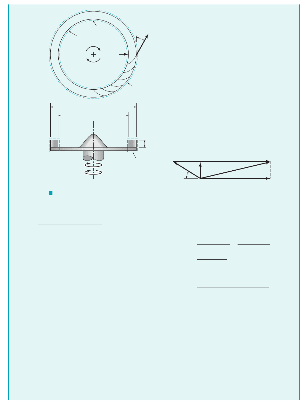
GIVEN An air fan has a bladed rotor of 12-in. outside di-
ameter and 10-in. inside diameter as illustrated in Fig.
E5.19a. The height of each rotor blade is constant at 1 in.
from blade inlet to outlet. The flowrate is steady, on a time-
average basis, at 230 ft
3
/min and the absolute velocity of the
air at blade inlet, V
1
, is radial. The blade discharge angle is
30 from the tangential direction. The rotor rotates at a con-
stant speed of 1725 rpm.
FIND Estimate the power required to run the fan.
S
OLUTION
Moment-of-Momentum—Power
From Eq. 1 we see that to calculate fan power, we need mass
flowrate, , rotor exit blade velocity, U
2
, and fluid tangential ve-
locity at blade exit, V
2
. The mass flowrate, , is easily obtained
from Eq. 5.6 as
(2)
Often, problems involving fans are solved using English Engi-
neering units. Since 1slug 32.174 lbm, we could have used as
the density of air
0.0766 lbm
ft
3
.
r
air
12.38 10
3
slug
ft
3
2132.174lbm
slug2
0.00912 slug/s
m
#
Q
12.38 10
3
slug/ft
3
21230 ft
3
/min2
160 s/min2
m
#
m
#
E
XAMPLE 5.19
We select a fixed and nondeforming control volume that includes
the rotating blades and the fluid within the blade row at an instant, as
shown with a dashed line in Fig. E5.19a. The flow within this con-
trol volume is cyclical, but steady in the mean. The only torque we
consider is the driving shaft torque, T
shaft
. This torque is provided by
a motor. We assume that the entering and leaving flows are each rep-
resented by uniformly distributed velocities and flow properties.
Since shaft power is sought, Eq. 5.53 is appropriate. Application of
Eq. 5.53 to the contents of the control volume in Fig. E5.19 gives
(1)W
#
shaft
m
#
1
1U
1
V
1
2 m
#
2
1U
2
V
2
2
0 1V
1
is radial2
JWCL068_ch05_187-262.qxd 9/23/08 10:02 AM Page 221
222 Chapter 5 ■ Finite Control Volume Analysis
Then
The rotor exit blade speed, U
2
, is
(3)
To determine the fluid tangential speed at the fan rotor exit, V
2
,
we use Eq. 5.43 to get
(4)
The vector addition of Eq. 4 is shown in the form of a “velocity
triangle” in Fig. E5.19b. From Fig. E5.19b, we can see that
(5)
To solve Eq. 5 for V
2
we need a value of W
2
, in addition to the
value of U
2
already determined (Eq. 3). To get W
2
, we recognize
that
(6)
where V
r2
is the radial component of either W
2
or V
2
. Also, us-
ing Eq. 5.6, we obtain
(7)
or since
(8)A
2
⫽ 2 r
2
h
m
#
⫽ A
2
V
r 2
W
2
sin 30° ⫽ V
r 2
V
2
⫽ U
2
⫺ W
2
cos 30°
V
2
⫽ W
2
⫹ U
2
⫽ 90.3 ft/s
U
2
⫽ r
2
⫽
16 in.211725 rpm212 rad/rev2
112 in./ft2160 s/min2
m
#
⫽
10.0766 lbm
Ⲑ
ft
3
21230 ft
3
Ⲑ
min2
160 s
Ⲑ
min2
⫽ 0.294 lbm
Ⲑ
s
where h is the blade height, Eqs. 7 and 8 combine to form
(9)
Taking Eqs. 6 and 9 together we get
(10)
Substituting known values into Eq. 10, we obtain
By using this value of W
2
in Eq. 5 we get
Equation 1 can now be used to obtain
with BG units.
With EE units
⫽
10.294 lbm
/
s2190.3 ft
/
s2164.9 ft
/
s2
332.174 1lbm ⴢ ft2
Ⲑ
1lb
Ⲑ
s
2
243550 1ft ⴢ lb2
/
1hp ⴢ s24
W
#
shaft
U
2
V
2
⫽
10.00912 slug/s2190.3 ft/s2164.9 ft/s2
31 1slug ⴢ ft/s
2
2/lb43550 1ft ⴢ lb2/1hp ⴢ s24
⫽ m
#
W
#
shaft
⫽ 90.3 ft/s ⫺ 129.3 ft/s210.8662⫽ 64.9 ft/s
V
2
⫽ U
2
⫺ W
2
cos 30°
⫽ 29.3 ft
Ⲑ
s
W
2
⫽
1230 ft
3
Ⲑ
min2112 in.
Ⲑ
ft2112 in.
Ⲑ
ft2
160 s
Ⲑ
min22p16 in.211 in.2 sin 30°
⫽
Q
2pr
2
h sin 30°
W
2
⫽
m
#
r2pr
2
h sin 30°
⫽
rQ
r2pr
2
h sin 30°
m
#
⫽ 2r
2
hV
r 2
ω
Section (1)
Fixed control volume
T
shaft
V
1
Section (2)
30°
W
2
ω
T
shaft
D
2
= 2r
2
= 12 in.
D
1
= 2r
1
= 10 in.
h =
1 in.
Fixed
control volume
W
2
W
r2
V
r2
U
2
V
2
(b)(a)
30°
V
2
θ
F I G U R E E5.19
JWCL068_ch05_187-262.qxd 9/23/08 10:03 AM Page 222

5.3 First Law of Thermodynamics—The Energy Equation 223
In either case
(Ans)
COMMENT Note that the “⫹” was used with the U
2
V
2
product because U
2
and V
2
are in the same direction. This result,
W
#
shaft
⫽ 0.097 hp
0.097 hp, is the power that needs to be delivered through the fan
shaft for the given conditions. Ideally, all of this power would go
into the flowing air. However, because of fluid friction, only some
of this power will produce useful effects (e.g., movement and pres-
sure rise) on the air. How much useful effect depends on the effi-
ciency of the energy transfer between the fan blades and the fluid.
5.3.1 Derivation of the Energy Equation
The first law of thermodynamics for a system is, in words
In symbolic form, this statement is
or
(5.55)
Some of these variables deserve a brief explanation before proceeding further. The total stored
energy per unit mass for each particle in the system, e, is related to the internal energy per unit
mass, the kinetic energy per unit mass, and the potential energy per unit mass, gz, by the
equation
(5.56)
The net rate of heat transfer into the system is denoted with and the net rate of work trans-
fer into the system is labeled Heat transfer and work transfer are considered going into
the system and coming out.
Equation 5.55 is valid for inertial and noninertial reference systems. We proceed to develop
the control volume statement of the first law of thermodynamics. For the control volume that is
coincident with the system at an instant of time
(5.57)
Furthermore, for the system and the contents of the coincident control volume that is fixed and
nondeforming, the Reynolds transport theorem 1Eq. 4.19 with the parameter b set equal to e2allows
us to conclude that
(5.58)
or in words,
the time rate
of increase
of the total
stored energy
of the system
⫽
the time rate of in-
crease of the total stored
energy of the contents
of the control volume
⫹
the net rate of flow
of the total stored energy
out of the control
volume through the
control surface
D
Dt
冮
sys
er dV⫺⫽
0
0t
冮
cv
er dV⫺⫹
冮
cs
erV ⴢ nˆ dA
1Q
#
net
in
⫹ W
#
net
in
2
sys
⫽ 1Q
#
net
in
⫹ W
#
net
in
2
coincident
control volume
“⫺”
“⫹”W
#
net in
.
Q
#
net in
,
e ⫽ uˇ ⫹
V
2
2
⫹ gz
V
2
Ⲑ
2,uˇ,
D
Dt
冮
sys
er dV⫺⫽1Q
#
net
in
⫹ W
#
net
in
2
sys
D
Dt
冮
sys
er dV⫺⫽a
a
Q
#
in
⫺
a
Q
#
out
b
sys
⫹ a
a
W
#
in
⫺
a
W
#
out
b
sys
time rate of net time rate of net time rate of
increase of the energy addition by energy addition by
total stored energy ⫽ heat transfer into ⫹ work transfer into
of the system the system the system
5.3 First Law of Thermodynamics—The Energy Equation
The first law of
thermodynamics is
a statement of con-
servation of energy.
JWCL068_ch05_187-262.qxd 9/23/08 10:04 AM Page 223

Combining Eqs. 5.55, 5.57, and 5.58 we get the control volume formula for the first law of ther-
modynamics:
(5.59)
The total stored energy per unit mass, e, in Eq. 5.59 is for fluid particles entering, leaving, and
within the control volume. Further explanation of the heat transfer and work transfer involved in
this equation follows.
The heat transfer rate, represents all of the ways in which energy is exchanged between
the control volume contents and surroundings because of a temperature difference. Thus, radiation,
conduction, and/or convection are possible. As shown by the figure in the margin, heat transfer
into the control volume is considered positive, heat transfer out is negative. In many engineering
applications, the process is adiabatic; the heat transfer rate, is zero. The net heat transfer rate,
can also be zero when
The work transfer rate, also called power, is positive when work is done on the contents
of the control volume by the surroundings. Otherwise, it is considered negative. Work can be trans-
ferred across the control surface in several ways. In the following paragraphs, we consider some
important forms of work transfer.
In many instances, work is transferred across the control surface by a moving shaft. In rotary
devices such as turbines, fans, and propellers, a rotating shaft transfers work across that portion of
the control surface that slices through the shaft. Even in reciprocating machines like positive dis-
placement internal combustion engines and compressors that utilize piston-in-cylinder arrangements,
a rotating crankshaft is used. Since work is the dot product of force and related displacement, rate
of work 1or power2is the dot product of force and related displacement per unit time. For a rotat-
ing shaft, the power transfer, is related to the shaft torque that causes the rotation, and
the angular velocity of the shaft, by the relationship
When the control surface cuts through the shaft material, the shaft torque is exerted by shaft ma-
terial at the control surface. To allow for consideration of problems involving more than one shaft
we use the notation
(5.60)
Work transfer can also occur at the control surface when a force associated with fluid nor-
mal stress acts over a distance. Consider the simple pipe flow illustrated in Fig. 5.6 and the con-
trol volume shown. For this situation, the fluid normal stress, is simply equal to the negative of
fluid pressure, p, in all directions; that is,
(5.61)
This relationship can be used with varying amounts of approximation for many engineering prob-
lems 1see Chapter 62.
The power transfer, , associated with a force F acting on an object moving with velocity V
is given by the dot product . This is illustrated by the figure in the margin. Hence, the power
transfer associated with normal stresses acting on a single fluid particle, can be evalu-
ated as the dot product of the normal stress force, and the fluid particle velocity, V, as
If the normal stress force is expressed as the product of local normal stress, and
fluid particle surface area, the result is
For all fluid particles on the control surface of Fig. 5.6 at the instant considered, power transfer
due to fluid normal stress, is
(5.62)W
#
normal
stress
⫽
冮
cs
sV ⴢ nˆ dA ⫽
冮
cs
⫺pV ⴢ nˆ dA
W
#
normal stress
,
dW
#
normal stress
⫽ snˆ dA ⴢ V ⫽⫺pnˆ dA ⴢ V ⫽⫺pV ⴢ nˆ dA
nˆ dA,
s ⫽⫺p,
dW
#
normal stress
⫽ dF
normal stress
ⴢ V
dF
normal stress
,
dW
#
normal stress
,
F ⴢ V
W
#
s ⫽⫺p
s,
W
#
shaft
net in
⫽
a
W
#
shaft
in
⫺
a
W
#
shaft
out
W
#
shaft
⫽ T
shaft
v
v,
T
shaft
,W
#
shaft
,
W
#
,
g Q
#
in
⫺ g Q
#
out
⫽ 0.Q
#
net in
,
Q
#
,
Q
#
,
0
0t
冮
cv
er dV⫺⫹
冮
cs
erV ⴢ nˆ dA ⫽ 1Q
#
net
in
⫹ W
#
net
in
2
cv
224 Chapter 5 ■ Finite Control Volume Analysis
The energy equa-
tion involves stored
energy and heat
and work transfer.
Control Volume
Q
•
4
Q
•
2
Q
•
3
Q
•
1
Q
•
net
= Q
•
1
+ Q
•
2
– Q
•
3
– Q
•
4
in
V
F
θ
W
•
= F
•
V
= FV cos
θ
JWCL068_ch05_187-262.qxd 9/23/08 10:04 AM Page 224
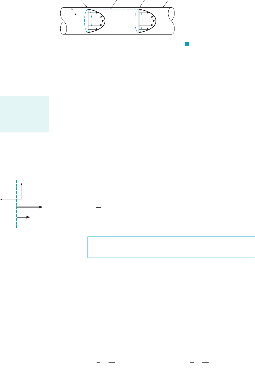
Note that the value of for particles on the wetted inside surface of the pipe is zero be-
cause is zero there. Thus, can be nonzero only where fluid enters and leaves the
control volume. Although only a simple pipe flow was considered, Eq. 5.62 is quite general and
the control volume used in this example can serve as a general model for other cases.
Work transfer can also occur at the control surface because of tangential stress forces. Ro-
tating shaft work is transferred by tangential stresses in the shaft material. For a fluid particle, shear
stress force power, can be evaluated as the dot product of tangential stress force,
and the fluid particle velocity, V. That is,
For the control volume of Fig. 5.6, the fluid particle velocity is zero everywhere on the wetted in-
side surface of the pipe. Thus, no tangential stress work is transferred across that portion of the
control surface. Furthermore, if we select the control surface so that it is perpendicular to the fluid
particle velocity, then the tangential stress force is also perpendicular to the velocity. Therefore,
the tangential stress work transfer is zero on that part of the control surface. This is illustrated in
the figure in the margin. Thus, in general, we select control volumes like the one of Fig. 5.6 and
consider fluid tangential stress power transfer to be negligibly small.
Using the information we have developed about power, we can express the first law of ther-
modynamics for the contents of a control volume by combining Eqs. 5.59, 5.60, and 5.62 to obtain
(5.63)
When the equation for total stored energy 1Eq. 5.562is considered with Eq. 5.63, we obtain the
energy equation:
(5.64)
5.3.2 Application of the Energy Equation
In Eq. 5.64, the term represents the time rate of change of the total stored energy,
e, of the contents of the control volume. This term is zero when the flow is steady. This term is
also zero in the mean when the flow is steady in the mean 1cyclical2.
In Eq. 5.64, the integrand of
can be nonzero only where fluid crosses the control surface Otherwise, is zero
and the integrand is zero for that portion of the control surface. If the properties within parenthe-
ses, and gz, are all assumed to be uniformly distributed over the flow cross-sectional
areas involved, the integration becomes simple and gives
(5.65)
a
flow
in
auˇ
p
r
V
2
2
gzb m
#
冮
cs
auˇ
p
r
V
2
2
gzb rV ⴢ nˆ dA
a
flow
out
auˇ
p
r
V
2
2
gzb m
#
uˇ, p
r, V
2
2,
V ⴢ nˆ1V ⴢ nˆ 02.
冮
cs
auˇ
p
r
V
2
2
gzb rV ⴢ nˆ dA
0
0t
兰
cv
er dV
0
0t
冮
cv
er dV
冮
cs
auˇ
p
r
V
2
2
gzb rV ⴢ nˆ dA Q
#
net
in
W
#
shaft
net in
0
0t
冮
cv
er dV
冮
cs
erV ⴢ nˆ dA Q
#
net
in
W
#
shaft
net in
冮
cs
pV ⴢ nˆ dA
dW
#
tangential stress
dF
tangential stress
ⴢ V
dF
tangential stress
,
dW
#
tangential stress
,
W
#
normal stress
V ⴢ nˆ
W
#
normal stress
5.3 First Law of Thermodynamics—The Energy Equation 225
F I G U R E 5.6 Simple, fully
developed pipe flow.
R
r
Section (1) Control volume Section (2) Pipe
u
max
u
max
u
1
= u
max
1 -
r
2
_
R
( )
[]
u
2
= u
max
1 -
r
2
_
R
( )
[]
Work is transferred
by rotating shafts,
normal stresses,
and tangential
stresses.
n
^
V
p
τ
W
•
tangential stress
= 0
δ
JWCL068_ch05_187-262.qxd 9/23/08 10:05 AM Page 225

Furthermore, if there is only one stream entering and leaving the control volume, then
(5.66)
Uniform flow as described above will occur in an infinitesimally small diameter streamtube as il-
lustrated in Fig. 5.7. This kind of streamtube flow is representative of the steady flow of a particle
of fluid along a pathline. We can also idealize actual conditions by disregarding nonuniformities
in a finite cross section of flow. We call this one-dimensional flow and although such uniform flow
rarely occurs in reality, the simplicity achieved with the one-dimensional approximation often jus-
tifies its use. More details about the effects of nonuniform distributions of velocities and other fluid
flow variables are considered in Section 5.3.4 and in Chapters 8, 9, and 10.
If shaft work is involved, the flow must be unsteady, at least locally 1see Refs. 1 and 22. The
flow in any fluid machine that involves shaft work is unsteady within that machine. For example,
the velocity and pressure at a fixed location near the rotating blades of a fan are unsteady. How-
ever, upstream and downstream of the machine, the flow may be steady. Most often shaft work is
associated with flow that is unsteady in a recurring or cyclical way. On a time-average basis for
flow that is one-dimensional, cyclical, and involves only one stream of fluid entering and leaving
the control volume, Eq. 5.64 can be simplified with the help of Eqs. 5.9 and 5.66 to form
(5.67)
We call Eq. 5.67 the one-dimensional energy equation for steady-in-the-mean flow. Note that Eq. 5.67
is valid for incompressible and compressible flows. Often, the fluid property called enthalpy, where
(5.68)
is used in Eq. 5.67. With enthalpy, the one-dimensional energy equation for steady-in-the-mean
flow 1Eq. 5.672is
(5.69)
Equation 5.69 is often used for solving compressible flow problems. Examples 5.20 and 5.21
illustrate how Eqs. 5.67 and 5.69 can be used.
m
#
ch
ˇ
out
⫺ h
ˇ
in
⫹
V
2
out
⫺ V
2
in
2
⫹ g1z
out
⫺ z
in
2d⫽ Q
#
net
in
⫹ W
#
shaft
net in
h
ˇ
⫽ uˇ ⫹
p
r
h
ˇ
,
m
#
cuˇ
out
⫺ uˇ
in
⫹ a
p
r
b
out
⫺ a
p
r
b
in
⫹
V
2
out
⫺ V
2
in
2
⫹ g1z
out
⫺ z
in
2d⫽ Q
#
net
in
⫹ W
#
shaft
net in
auˇ ⫹
p
r
⫹
V
2
2
⫹ gzb
out
m
#
out
⫺ auˇ ⫹
p
r
⫹
V
2
2
⫹ gzb
in
m
#
in
冮
cs
auˇ ⫹
p
r
⫹
V
2
2
⫹ gzb rV ⴢ nˆ dA ⫽
226 Chapter 5 ■ Finite Control Volume Analysis
F I G U R E 5.7
Streamtube flow.
Streamtube
dA
m
•
in
m
•
out
V
The energy equa-
tion is sometimes
written in terms of
enthalpy.
GIVEN A pump delivers water at a steady rate of 300 gal/min as
shown in Fig. E5.20. Just upstream of the pump [section (1)]
where the pipe diameter is 3.5 in., the pressure is 18 psi. Just
downstream of the pump [section (2)] where the pipe diameter is
1 in., the pressure is 60 psi. The change in water elevation across
Energy—Pump Power
E
XAMPLE 5.20
the pump is zero. The rise in internal energy of water, , as-
sociated with a temperature rise across the pump is 93 ft lb/lbm.
The pumping process is considered to be adiabatic.
FIND Determine the power (hp) required by the pump.
ⴢ
u
ˇ
2
⫺ u
ˇ
1
JWCL068_ch05_187-262.qxd 9/23/08 10:05 AM Page 226