Morling K. Geometric and Engineering Drawing
Подождите немного. Документ загружается.


Geometric and Engineering Drawing164
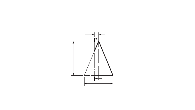
11. Figure 7 shows a right cone cut by a plane X – X. Draw the given view and project an
elevation seen from the left of the given view.
10
95
X
Dimensions in mm
X
φ 80
Figure 7
12. Draw the conic having an eccentricity of
3
4
and a focus which is 38 mm from the directrix.
State the name of this curve.
Associated Examining Board

Geometric and Engineering Drawing. DOI:
© 2010 Elsevier Ltd. All rights reserved.2010
10.1016/B978-0-08-096768-4.00012-7
Intersection of Regular Solids
12
When two solids interpenetrate, a line of intersection is formed. It is sometimes nec-
essary to know the exact shape of this line, usually so that an accurate development
of either or both of the solids can be drawn. This chapter shows the lines of intersec-
tion formed when some of the simpler geometric solids interpenetrate.
Two dissimilar square prisms meeting at right angles ( Fig. 12.1 ).
1
First angle projection
4
1, 3
2
1
2
3
4
2, 4
3
Figure 12.1
The EE shows where corners 1 and 3 meet the larger prism and these are pro-
jected across to the FE The plan shows where corners 2 and 4 meet the larger prism
and this is projected up to the FE.

Geometric and Engineering Drawing166
Two dissimilar square prisms meeting at an angle ( Fig. 12.2 ).
The FE shows where corners 1 and 3 meet the larger prism. The plan shows where
corners 2 and 4 meet the larger prism and this is projected down to the FE.
Third angle projection
2
1
24
3
4
1
1
2, 4
3
3
Figure 12.2
A hexagonal prism meeting a square prism at right angles ( Fig. 12.3 ).
The plan shows where all the corners of the hexagonal prism meet the square
prism. These are projected down to the FE to meet the projectors from the same cor-
ners on the EE.
3
2, 4
Third angle projection
1, 5
1, 2
12
36
54
3, 6
4, 5
6
Figure 12.3

Intersection of Regular Solids 167
1
1
6
1, 5
2, 4
3
2
3
4
5
6
First angle projection
2
36
54
Figure 12.4
Two dissimilar hexagonal prisms meeting at an angle ( Fig. 12.4 ).
The FE shows where corners 3 and 6 meet the larger prism. The plan shows where
corners 1, 2, 4 and 5 meet the larger prism and these are projected up to the FE.
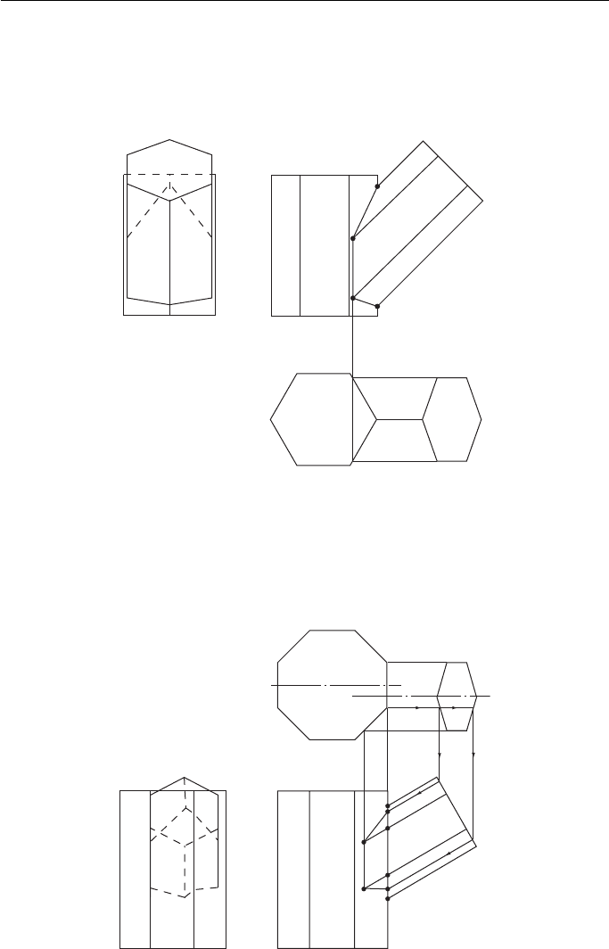
A hexagonal prism meeting an octagonal prism at an angle, their centres not
being in the same VP ( Fig. 12.5 ).
Third angle projection
12
36
a,b
6
5
a
b
4
3
2
1
54
6
1, 5
2, 4
3
b
a
Figure 12.5

Geometric and Engineering Drawing168
The FE shows where corners 3 and 6 meet the octagonal prism. The plan shows where
corners 1, 2, 4 and 5 meet the octagonal prism and these are projected down to the FE.
The sides of the hexagonal prism between corners 3 – 4 and 5 – 6 meet two sides of
the octagonal prism. The change of shape occurs at points a and b. The position of
a and b on the FE (and then across to the EE) is found by projecting down to the FE
via the end of the hexagonal prism (follow the arrows). The intersection on the FE
can then be completed.
A square prism meeting a square pyramid at right angles ( Fig. 12.6 ).
The EE shows where corners 1 and 3 meet the pyramid.
These are projected across to the FE.
Corners 2 and 4 are not quite so obvious. The pictorial view shows how these cor-
ners meet the pyramid. If the pyramid was cut across X – X, the section of the pyra-
mid resulting would be square, and points 2 and 4 would lie on this square. It is not
necessary to make a complete, shaded section on your drawing but it is necessary
to draw the square on the plan. Since points 2 and 4 lie on this square it is simple
to find their exact position. Project corners 2 and 4 from the EE onto the plan. The
points where these projectors meet the square are the exact positions of the intersec-
tions of corners 2 and 4 with the pyramid.
Third angle projection
2
3
4
1
2, 4
2
4
1
3
XX
3
1
Pictorial view with part
above X–X removed
2
4
Figure 12.6
A square pyramid and a hexagonal prism meeting at an angle ( Fig. 12.7 ).
The FE shows where corners 1 and 4 meet the pyramid.
Corners 2 and 6 lie on the same plane X – X. If this plane is marked on the plan
view of the pyramid (follow the arrows) it results in the line X – X – X. Corners 2 and
6 lie on this plane; their exact positions are as shown.

Intersection of Regular Solids 169
First angle projection
6
1
1
2
X
X
Y
Y
6
3
5
2
3
XY4
5
6
1
4
2
3
4
5
Y
X
X
Y
Figure 12.7
Corners 3 and 5 lie on the same plane Y – Y. On the plan view this plane is seen
as the line Y – Y – Y (follow the arrows). Corners 3 and 5 lie on this plane; their exact
positions are as shown.
Two dissimilar cylinders meeting at right angles ( Fig. 12.8 ).
The smaller cylinder is divided into 12 equal sectors on the FE and on the plan
(the EE shows how these are arranged round the cylinder).
The plan shows where these sectors meet the larger cylinder and these intersections
are projected down to the FE to meet their corresponding sector at 1 , 2 , 3 , etc.
4
3
2
1
12
11
10
9
8
7
5
6
1
Third angle projection
4
4′
3′,5′
2′,6′,
1′,7′,
12′,8′,
11′,9′
10′
3,5
2,6
1,7
8,12
9,11
10
2,12
3,11
4,10
5,9
6,8
7
Figure 12.8

Geometric and Engineering Drawing170
Two dissimilar cylinders meeting at an angle ( Fig. 12.9 ).
The method is identical with that of the last problem. The smaller cylinder is
divided into 12 equal sectors on the FE and on the plan.
The plan shows where these sectors meet the larger cylinder and these intersec-
tions are projected up to the FE to meet their corresponding sectors at 1 , 2 , 3 , etc.
Two dissimilar cylinders meeting at an angle, their centres not being in the
same VP ( Fig. 12.10 ).
Once again, the method is identical with that of the previous example. The smaller
cylinder is divided into 12 equal sectors on the FE and on the plan.
The plan shows where the sectors meet the larger cylinder and these intersections
are projected down to the FE to meet their corresponding sectors at 1 , 2 , 3 , etc.
4
1
1
2
First angle projection
3
4
5
6
7
8
9
10
11
12
2,12
3,11
4,10
5,9
6,8
7
1′
2′
12′
11′
3′
4′
5′
6′
8′
7′
9′
10′
3,5
2,6
1,7
8,12
9,11
10
Figure 12.9
4
Third angle projection
7
6,8
5,9
4,10
3,11
2,12
1
1′
12′
11′
10′
9′
8′
7′
6′
5′
4′
3′
2′
3,5
2,6
1,7
12,8
11,9
10
10
11
12
2
1
3
4
5
6
7
8
9
Figure 12.10

Intersection of Regular Solids 171
A cylinder meeting a square pyramid at right angles ( Fig. 12.11 ).
The FE shows where points 1 and 7 meet the pyramid and these are projected
down to the plan.
Consider the position of point 2. Since the cylinder and the pyramid interpene-
trate, point 2 lies on both the cylinder and the pyramid. Its position on the cylinder is
seen fairly easily. On the FE it lies on the line marked 2,12 and on the plan it lies on
the line marked 2,6. Its position on the pyramid is not quite so obvious. Imagine, on
the FE that the part of the pyramid that is above the line 2,12 was removed. The sec-
tion that resulted across the pyramid would be a square and point 2 would lie some-
where along the perimeter of that square. It is not necessary to construct a complete,
shaded section across the pyramid at line 2,12 but the square that would result from
such a section is constructed on the plan. In Fig. 12.11 this is marked as ‘ SQ 2,12 ’ .
Since point 2 lies somewhere along the line 2,6 (in the plan) then its exact position is
at the intersection of the square and the line. This is shown on the plan as 2 .
Point 12 is the intersection of the same square and the line 8,12 (in the plan).
This process is repeated for each point in turn. When the intersection has been
completed in the plan, it is a simple matter to project the points up onto the FE and
draw the intersection there.
1
2
3
4
5
6
7
8
9
10
11
12
10
1
2,12
First angle projection
3,11
4,10
5,9
6,8
7
9,11
8,12
1,7
2,6
3,5
4
10′
9′
8′
7′
11′
12′
1′
2′
6′
5′
3′
4′
SQ 2, 12
SQ 3, 11
SQ 4, 10
SQ 5, 9
SQ 6, 8
Figure 12.11

Geometric and Engineering Drawing172
A cylinder meeting a square pyramid at an angle ( Fig. 12.12 ).
The FE shows where points 1 and 7 meet the pyramid and these are projected
down to the plan.
Consider the position of the point 2. In the FE it lies somewhere along the line
marked 2,12, while in the plan it lies on the line marked 6,2. If that part of the pyramid
above the line 2,12 in the FE was removed, the point 2 would lie on the perimeter of
the resulting section. This perimeter can be drawn on the plan and, in Fig. 12.12 , it is
shown as the line marked ‘ SECT 2,12 ’ . Point 2 must lie on this line; it must also lie
on the line marked 6,2 and its exact position is the intersection of these two lines.
Point 12 is the intersection of the same section line and the line marked 8,12.
This process is repeated for each point in turn. When the plan is complete, the
intersection can be projected onto the other two views. For the sake of clarity, these
projections are not shown.
1
2,12
3,11
4,10
5,9
6,8
7
9,11
10
8,12
7,1
6,2
5,3
4
First angle projection
12′
1
2
3
4
5
6
8
7
9
10
11
12
10′
11′
1′
2′
3′
4′
5′
6′
7′
8′
9′
Sect 2,12
Sect 3,11
Sect 4,10
Sect 5,9
Sect 6,8
Figure 12.12

Intersection of Regular Solids 173
A cylinder meeting a hexagonal pyramid at an angle ( Fig. 12.13 ).
Once again lines are drawn on the plan which represent the perimeters of sections
taken on the FE on lines 1; 2,12; 3,11, etc. All the construction lines on Fig. 12.13
are for finding these section perimeters.
The line of interpenetration, first drawn on the plan, is the intersection of the line
1,7 with section 1, line 2,6 with section 2,12 (giving point 2 ), line 3,5 with section
3,11 (giving point 3 ), line 4 with section 4,10, etc.
When the intersection is complete on the plan, it can be projected onto the other
two elevations. For the sake of clarity, these projections are not shown.
Sect 7
Sect 6,8
Sect 5,9
Sect 4,10
Sect 3,11
Sect 2,12
Sect 1
4
3,5
2,6
12,8
1,7
11,9
10
3,11
4,10
5,9
6,8
2,12
1
7
2′
1′
12′
11′
10′
3′
4′
5′
6′
7′
8′
9′
Third angle projection
Figure 12.13
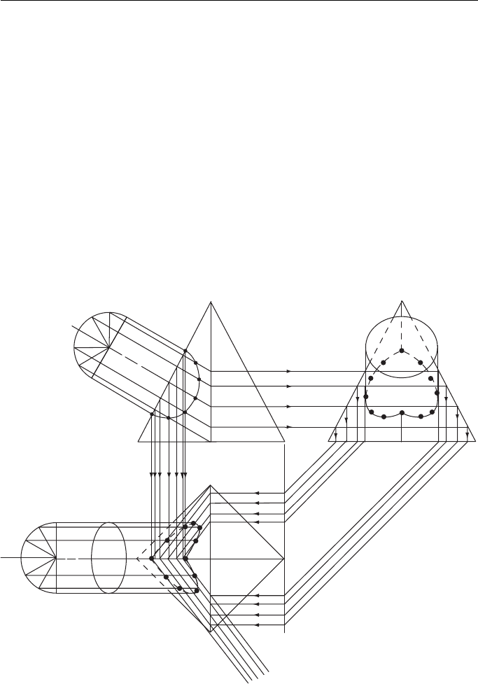
A cylinder meeting a cone, the cone enveloping the cylinder ( Fig. 12.14 ).
The cylinder is divided into 12 equal sectors on the FE and on the plan.
Consider point 2. On the FE it lies somewhere along the line marked 2,12 whilst
on the plan it lies on the line marked 2,6. If, on the FE, that part of the cone above the
line 2,12 was removed, point 2 would lie somewhere on the perimeter of the resulting
