Morling K. Geometric and Engineering Drawing
Подождите немного. Документ загружается.


Geometric and Engineering Drawing184
11. Two views (one incomplete) of a connecting rod end are shown in Fig. 10 . The original diam-
eters were 126 mm and 62 mm and the transition between these followed a circular path of
radius 75 mm. Two flat parallel faces were then milled as shown in the EE. Draw the given
views, complete the left-hand elevation and beneath this project a plan. Scale: full size.
Oxford Local Examinations
32
Dimensions in mm
R75
88
φ 126
φ 62
Figure 10

Geometric and Engineering Drawing. DOI:
© 2010 Elsevier Ltd. All rights reserved.2010
10.1016/B978-0-08-096768-4.00013-9
Further Orthographic Projection
The first five diagrams of Chapter 10 show the basic principles of orthographic projec-
tion. These diagrams should be thoroughly understood before this chapter is attempted.
The object to be drawn is suspended between three planes called the FVP, the EVP and
the horizontal plane HP. These planes are at right angles, and a view of the object is
projected onto each of the planes. These views are called the FE, the EE and the plan.
Two of the planes are then swung back, as if on hinges, until all three planes are in the
same plane, i.e. they would all lie on the same flat surface. This system of swinging the
planes until they are in line is called ‘ rabatment ’ .
Definitions
When a line passes through a plane, the point of intersection is called a ‘ trace ’ .
When a plane passes through another plane, the line of intersection is also called
a ‘ trace ’ .
The Straight Line
The projection of a line that is not parallel to any of the principal planes.
Figure 13.1 shows a straight line AB suspended between the three principal
planes. Projectors from A and B, perpendicular to the planes, give the projection of
AB on each of the principal planes. On the right of Fig. 13.1 can be seen the projec-
tions of the line after rabatment.
13
HP
FVP
EVP
Z
Y
X
b
B
A
O
b
2
b
1
a
2
a
1
a
FVP
HP
Third angle projection
b
1
b
2
a
1
a
2
a
b
EVP
O
YX
Z
Y
Figure 13.1
Geometric and Engineering Drawing186
A trace is the line resulting from the intersection of two planes. The trace of the
FVP and the HP is the line OX. The trace of the EVP and the HP is the line OY.
The trace of the FVP and the EVP is the line OZ. These lines are often very useful
for reference purposes and they should be marked on your drawings. The O is often
ignored and the traces are then shown as XY and YZ.
To find the true length of a line that is not parallel to any of the principal
planes and to find the angle that the line makes with the FVP ( Fig. 13.2 ).
Y
X
B
a
1
a
b
FVP
HP
b
1
A
Y
X
B
B′
a
1
a
b
FVP
HP
b
1
A
Y
X
B′
b′
a
1
a
FVP
HP
b
2
A
a
1
b
2
a
FVP
HP
θ
θ
YX
b′
b
b
1
Third angle projection
Initial conditions
(AB is not parallel
to either plane)
End A is kept stationary
and B is swung round so
that AB is parallel to HP
Line is projected from
new position to show
true length on HP and
the angle that line
makes with FVP
True length
True length
Figure 13.2
The line is AB. On the FVP it is seen as ab and on the HP as a
1
b
1
.
One end of the line A is kept stationary whilst B is swung round so that AB is
parallel to the HP. B is now at B , and on the FVP, b is now at b . Since the line is
parallel to the HP it will project its true length onto the HP. This is shown as a
1
b
2
.
Note that b
1
and b
2
are the same distance from the line XY.
Since AB (and ab ) are parallel to the HP, the angle that AB makes with the FVP
can be measured. This is shown as θ .
Further Orthographic Projection 187
Y
a
B
b
b
1
a
1
A
HP
FVP
X
Y
a
B
b
b
1
a
1
A
A′
HP
FVP
X
Y
B
b
b
1
a
2
a′
A′
HP
FVP
X
FVP
True length
True length
HP
φ
φ
a′
b
1
a
1
a
2
a
b
YX
Initial conditions
(AB is not parallel
to either plane)
End B is kept stationary
and A is swung round so
that AB is parallel
with the FVP
Line is projected from
new position to show
true length on FVP
and the angle that line
makes with HP
Third angle projection
Figure 13.3
To find the true length of a line that is not parallel to any of the principal
planes and to find the angle that the line makes with the HP ( Fig. 13.3 ).
The line is AB. On the FVP it is seen as ab and on the HP as a
1
b
1
.
One end of the line B is kept stationary while A is swung round so that AB
is parallel to the FVP. A is now at A and, on the HP, a is now at a . Since the line is
now parallel to the FVP it will project its true length onto the FVP. This is shown as
a
2
b. Note that a
2
and a are the same distance from the line XY.
Since BA (and b
1
a ) are parallel to the FVP, the angle that AB makes with the
HP can be measured. This is shown as φ .
Geometric and Engineering Drawing188
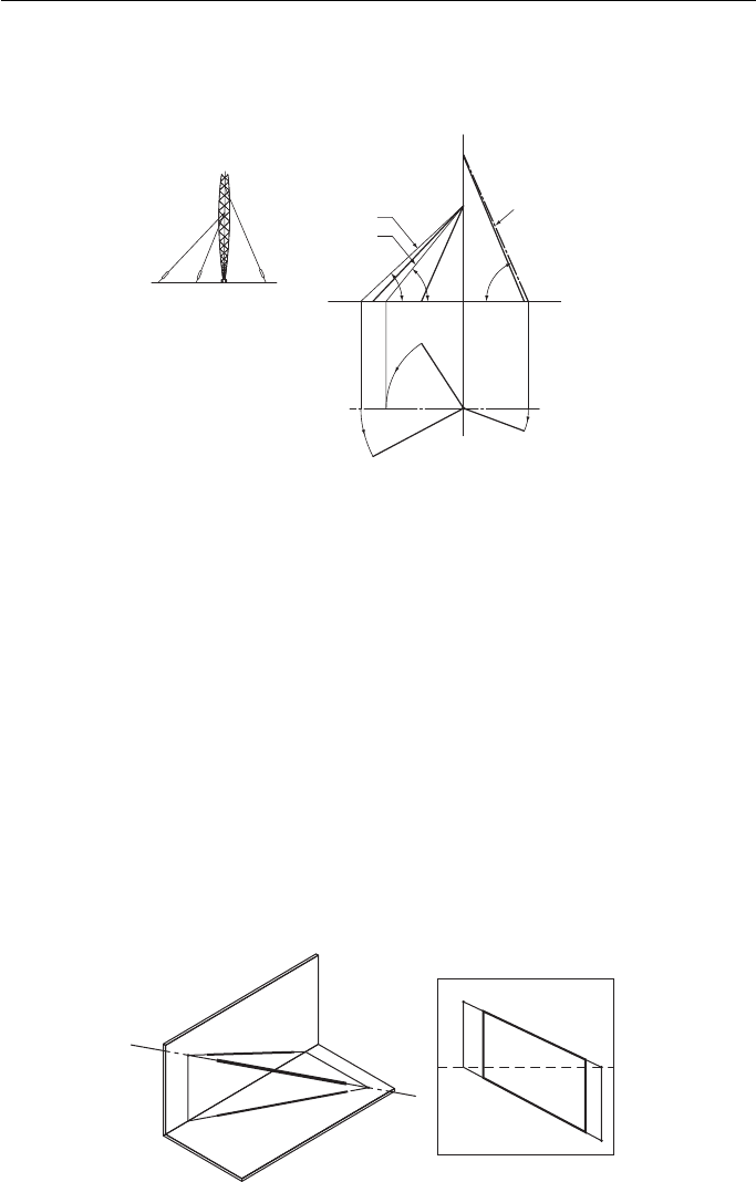
Figure 13.4 is an example of an application of the theory shown above. It shows
how simple it is to apply this theory.
First angle projection
True length BC
True length AE
True length BD
X
C
C
D
D
E
E
A
B
A
B
Y
Figure 13.4
HP
HP
FVP
FVP
T
v
T
v
a
a
b
b
X
First angle projection
Y
T
h
T
h
B
Y
X
b
1
a
1
a
1
A
b
1
Figure 13.5
A pylon is supported by three hawsers. Given the plan and elevation of the haw-
sers, find their true lengths and the angle that they make with the ground.
In the plan, each hawser is swung round until it is parallel to the FVP. The new
positions of the ends of the hawsers are projected up to the FE and joined to the
pylon at A and B. This gives the true lengths and the angles.
To find the traces of a straight line given the plan and elevation of the line
( Fig. 13.5 ).
The line is AB. If the line is produced it will pass through both planes, giving
traces T
v
and T
h
.
ab is produced to meet the XY line. This intersection is projected down to meet
a
1
b
1
produced in T
h
.
b
1
a
1
is produced to meet the XY line. This intersection is projected up to meet ba
produced in T
v
.
Further Orthographic Projection 189
To draw the elevation and plan of a line AB given its true length and the dis-
tances of the ends of the line from the principal planes, in this case a
v
and a
h
,
and b
v
and b
h
( Fig. 13.6 ).
XY
b
h
b
v
a
v
a
h
a
First angle projection
b
c
R = True length AB
D
b
1
a
1
Figure 13.6
1. Fix points a and a
1
at the given distances a
v
and a
h
from the XY line. These are measured
on a common perpendicular to XY.
2. Draw a line parallel to XY, distance b
v
from XY.
3. With centre a, radius equal to the true length AB, draw an arc to cut the line drawn parallel
to XY in C.
4. From a
1
draw a line parallel to XY to meet a line from C drawn perpendicular to XY in D.
5. Draw a line parallel to XY, distance b
h
from XY.
6. With centre a
1,
radius a
1
D, draw an arc to cut the line drawn parallel to XY in b
1
.
7. Draw a line from b
1
, perpendicular to XY to meet the line drawn parallel to XY through C in b.
ab is the elevation of the line.
a
1
b
1
is the plan of the line.
To construct the plan of a line AB given the distance of one end of the line from
the XY line in the plan ( a
h
), the true length of the line and the elevation ( Fig. 13.7 ).
YX
D
b
1
a
1
a
b
c
a
h
Third angle projection
R = True length AB
Figure 13.7
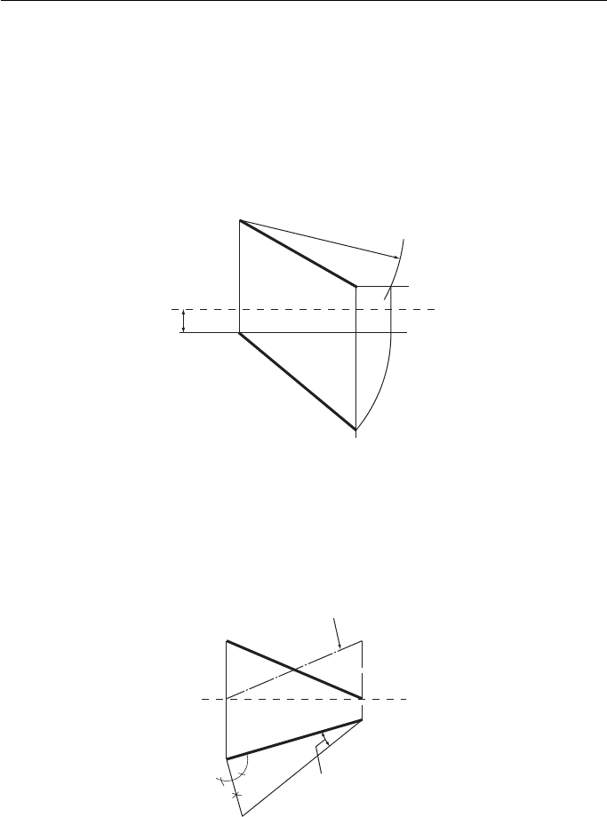
1. From b draw a line parallel to the XY line.
2. With centre a, radius equal to the true length of the line AB, draw an arc to cut the parallel
line in C.
Geometric and Engineering Drawing190
3. From a
1
(given) draw a line parallel to the XY line to meet a line drawn from C perpen-
dicular to XY in D.
4. With centre a
1
, radius equal to a
1
D, draw an arc to meet a line drawn from b perpendicular
to XY in b
1
.
a
1
b
1
is the plan of the line.
To construct the elevation of a line given the distance of one end of the line from
the XY line in the elevation, the true length of the line and the plan ( Fig. 13.8 ).
Third angle projection
a
1
b
1
C
a
v
a
b
D
XY
R = True length AB
Figure 13.8
This construction is very similar to the last one and can be followed from the
instructions given for that example.
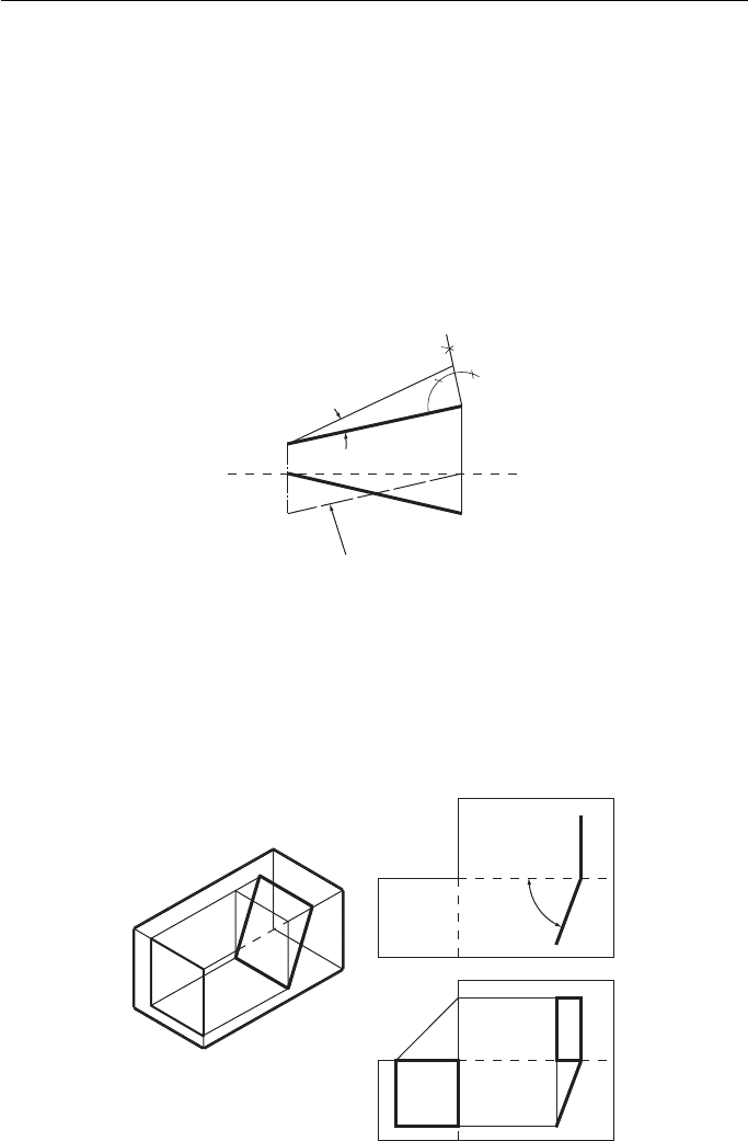
To construct the elevation of a line AB given the plan of the line and the angle
that the line makes with the HP ( Fig. 13.9 ).
a
XY
Given angle
a
1
b
C
b
1
First angle projection
Alternative solution
Figure 13.9
1. Draw the plan and from one end erect a perpendicular.
2. From the other end of the plan draw a line at the angle given to intersect the perpendicular
in C.
3. From b
1
draw a line perpendicular to XY to meet XY in b .
4. From a
1
draw a line perpendicular to XY and mark off XY to a equal to a
1
c .
ab is the required elevation. An alternative solution is also shown.
Further Orthographic Projection 191
The Inclined Plane
Definition
An inclined plane is inclined to two of the principal planes and perpendicular to the
third.
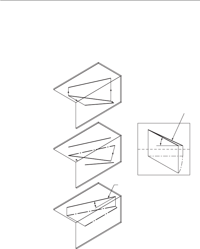
Figure 13.10 shows a rectangular plane that is inclined to the HP and the EVP,
and is perpendicular to the FVP. Because it is perpendicular to the FVP, the true
angle between the inclined plane and the HP can be measured on the FVP. This is the
angle φ .
First angle projection
Given angle
XY
Alternative solution
b
1
a
1
a
b
C
Figure 13.10
To draw the plan of a line AB given the elevation of the line and the angle
that the line makes with the VP ( Fig. 13.11 ).
HP
H
T
V
Z
The inclined plane
X
Y
EVP
FVP
Y
Z
Y
EVP FVP V
φ
X
T
H
HP
Traces of plane
Y
Z
Y
EVP FVP
HP
V
X
T
H
Projection of plane
Third angle projection
Figure 13.11

Geometric and Engineering Drawing192
This construction is very similar to the last one and can be followed from the
instructions given for that example.
The top drawing shows the traces of the plane after rabatment. The bottom draw-
ing shows the full projection of the plane. It should be obvious how the full projec-
tion is obtained if you are given the traces and told that the plane is rectangular.
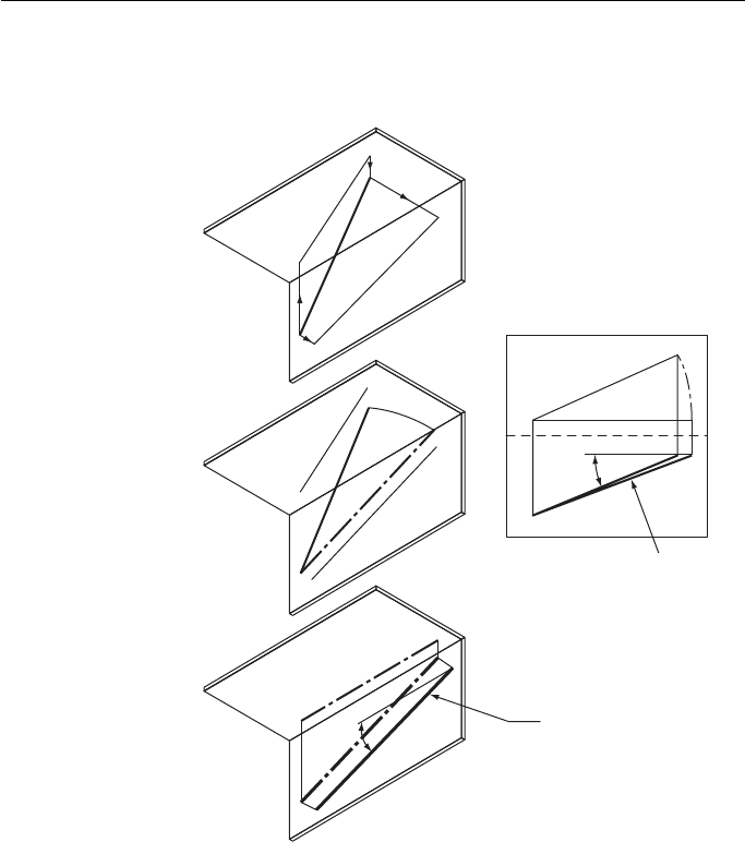
Figure 13.12 shows a triangular plane inclined to the FVP and the EVP, and per-
pendicular to the HP. Because it is perpendicular to the HP, the true angle between
the inclined plane and the FVP can be measured on the HP. This angle is θ .
Once again, it should be obvious how the full projection of the inclined plane is
obtained if you are given the traces and told that the plane is triangular.
HP
H
T
V
V
Z
Third angle projection
Traces of plane
X
Y
XY
H
HP
T
θ
Y
EVP
FVP
Z
Y
XY
FVPEVP
FVPEVP
T
HP
H
V
Z
Projection of plane
Figure 13.12
To find the true shape of an inclined plane.
If the inclined plane is swung round so that it is parallel to one of the reference
planes, the true shape can be projected. In Fig. 13.13 , the plan of the plane, HT, is
swung round to H T. The true shape of the plane can then be drawn on the FVP.
HP
FVP
True shape
Third angle projection
X
T
H
Y
HP
V
V
H
H′
H′
FVP
T
XY
Figure 13.13

Further Orthographic Projection 193
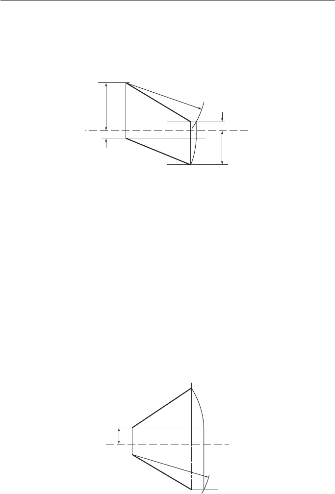
Figure 13.14 shows an example. An oblique, truncated, rectangular pyramid
stands on its base. The problem is to find the true shape of sides A and B.
In the FE, side A is swung upright and its vertical height is projected across to the
EE where the true shape of side A can be drawn.
In the EE, side B is swung upright and projected across to the FE where the true
shape is drawn.
True shape side A
Side A
Third angle projection
Side B
True shape side B
Figure 13.14
The Oblique Plane
Definition
An oblique plane is a plane that is inclined to all of the principal planes.
Figure 13.15 shows a quadrilateral plane that is inclined to all three principal
planes.
T
T
V
Z
H
Third angle projection
Y
Y
X
T
T
HP
EVP FVP
Traces of plane
Projection of plane
X
V
H
Y
Z
Y
T
T
HP
EVP FVP
Z
X
V
H
EVP
EVP
HP
Y
Figure 13.15
