Moran M.J., Shapiro H.N. Fundamentals of Engineering Thermodynamics
Подождите немного. Документ загружается.

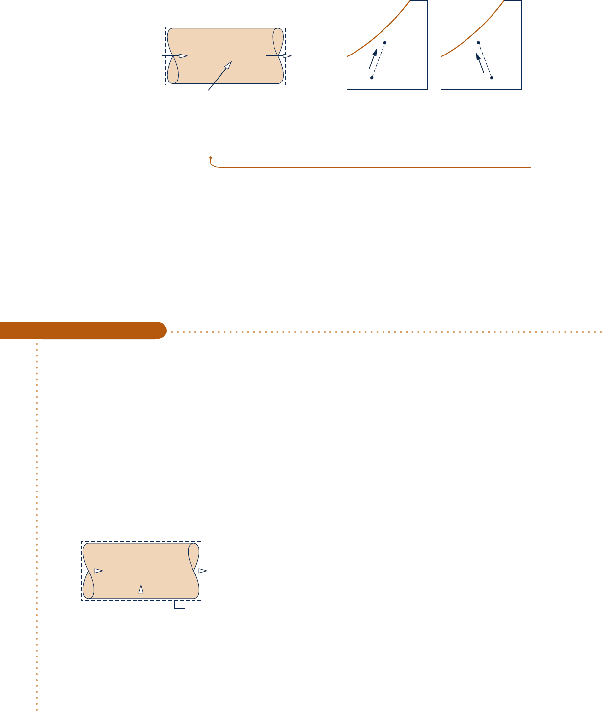
12.8.2 Conditioning Moist Air at Constant Composition
Building air-conditioning systems frequently heat or cool a moist air stream with no
change in the amount of water vapor present. In such cases the humidity ratio v remains
constant, while relative humidity and other moist air parameters vary. Example 12.10
gives an elementary illustration using the methodology of Sec. 12.8.1.
Heating Moist Air in a Duct
c c c c EXAMPLE 12.10 c
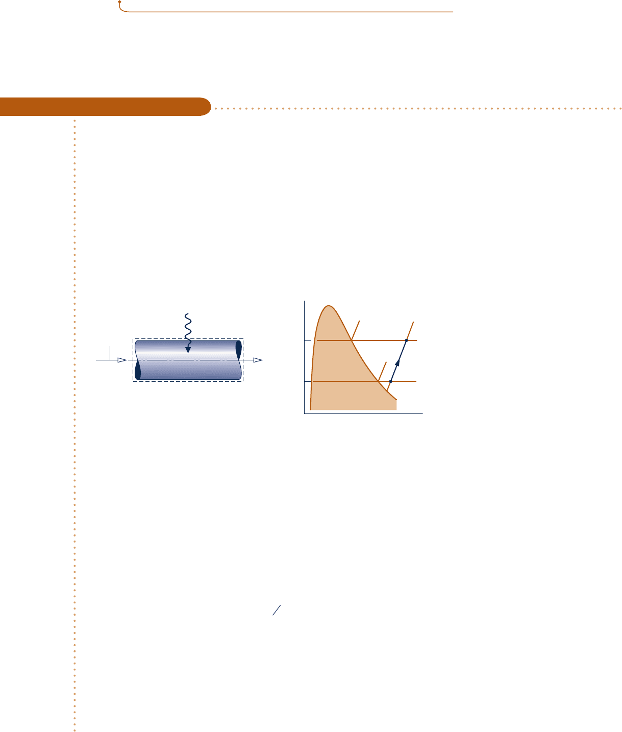
Moist air enters a duct at 108C, 80% relative humidity, and a volumetric flow rate of 150 m
3
/min. The mixture
is heated as it flows through the duct and exits at 308C. No moisture is added or removed, and the mixture pres-
sure remains approximately constant at 1 bar. For steady-state operation, determine (a) the rate of heat transfer,
in kJ/min, and (b) the relative humidity at the exit. Changes in kinetic and potential energy can be ignored.
SOLUTION
Known:
Moist air that enters a duct at 108C and f 5 80% with a volumetric flow rate of 150 m
3
/min is heated
at constant pressure and exits at 308C. No moisture is added or removed.
Find: Determine the rate of heat transfer, in kJ/min, and the relative humidity at the exit.
Schematic and Given Data:
Engineering Model:
1.
The control volume shown in
the accompanying figure
operates at steady state.
2. The changes in kinetic and
potential energy between inlet
and exit can be ignored and
W
#
cv
5 0.
3. The entering and exiting
moist air streams are regarded
as ideal gas mixtures adhering
to the Dalton model.
Fig. E12.10a
T
T
2
T
1
v
p
v
p
g
(T
1
)
p
g
(T
2
)
2
1
Q
·
cv
Boundary
T
2
= 30°C
12
= 150
= 10°C
= 80%
(AV)
1
T
1
1
φ
m
3
___
min
Analysis:
(a)
The heat transfer rate
Q
#
cv
can be determined from the mass and energy rate balances. At steady state, the
amounts of dry air and water vapor contained within the control volume cannot vary. Thus, for each component
individually it is necessary for the incoming and outgoing mass flow rates to be equal. That is
m
#
a1
5 m
#
a2
1
dry air
2
m
#
v1
5 m
#
v2
1
water vapor
2
For simplicity, the constant mass flow rates of the dry air and water vapor are denoted, respectively, by m
#
a
and m
#
v
.
From these considerations, it can be concluded that the humidity ratio is the same at the inlet and exit: v
1
5 v
2
.
The steady-state form of the energy rate balance reduces with assumption 2 to
0 5 Q
#
cv
2 W
#
0
cv
1 1m
#
a
h
a1
1 m
#
v
h
v1
2
2
1m
#
a
h
a2
1 m
#
v
h
v2
2
In writing this equation, the incoming and outgoing moist air streams are regarded as ideal gas mixtures of dry
air and water vapor.
Solving for Q
#
cv
Q
#
cv
5 m
#
a
1
h
a
2
2 h
a
1
2
1 m
#
v
1
h
v
2
2 h
v
1
2
12.8 Analyzing Air-Conditioning Processes 743
c12IdealGasMixtureandPsychromet743 Page 743 6/29/10 11:57:33 AM user-s146 c12IdealGasMixtureandPsychromet743 Page 743 6/29/10 11:57:33 AM user-s146 /Users/user-s146/Desktop/Merry_X-Mas/New/Users/user-s146/Desktop/Merry_X-Mas/New

744 Chapter 12
Ideal Gas Mixture and Psychrometric Applications
Noting that m
#
v
5 vm
#
a
, where v is the humidity ratio, the expression for
Q
#
cv
can be written in the form
➊
Q
#
cv
5 m
#
a
31h
a2
2 h
a1
21 v1h
v2
2 h
v1
24 (a)
To evaluate
Q
#
cv
from this expression requires the specific enthalpies of the dry air and water vapor at the inlet
and exit, the mass flow rate of the dry air, and the humidity ratio.
The specific enthalpies of the dry air are obtained from Table A-22 at the inlet and exit temperatures T
1
and
T
2
, respectively: h
a1
5 283.1 kJ/kg, h
a2
5 303.2 kJ/kg. The specific enthalpies of the water vapor are found using
h
v
< h
g
and data from Table A-2 at T
1
and T
2
, respectively: h
g1
5 2519.8 kJ/kg, h
g2
5 2556.3 kJ/kg.
The mass flow rate of the dry air can be determined from the volumetric flow rate at the inlet (AV)
1
m
#
a
5
1
AV
2
1
y
a
1
In this equation, y
a1
is the specific volume of the dry air evaluated at T
1
and the partial pressure of the dry air
p
a1
. Using the ideal gas equation of state
y
a1
5
1R
/
M2T
1
p
a
1
The partial pressure p
a1
can be determined from the mixture pressure p and the partial pressure of the water
vapor p
v1
: p
a1
5 p 2 p
v1
. To find p
v1
, use the given inlet relative humidity and the saturation pressure at 108C
from Table A-2
p
v1
5 f
1
p
g
1
5
1
0.8
21
0.01228 bar
2
5 0.0098 bar
Since the mixture pressure is 1 bar, it follows that p
a1
5 0.9902 bar. The specific volume of the dry air is then
y
a1
5
a
8314 N ? m
28.97 kg ? K
b
1283 K2
1
0.9902 3 10
5
N
/
m
2
2
5 0.82 m
3
/
kg
Using this value, the mass flow rate of the dry air is
m
#
a
5
150 m
3
/
min
0.82 m
3
/
k
g
5 182.9 kg
/
min
The humidity ratio v can be found from
v 5 0.622
a
p
v1
p 2 p
v1
b
5 0.622
a
0.0098
1 2 0.0098
b
5 0.00616
kg
1
vapor
2
kg
1
dry air
2
Finally, substituting values into Eq. (a) we get
Q
#
cv
5 182.9
31
303.2 2 283.1
2
1
1
0.00616
21
2556.3 2 2519.8
24
5
3
717 k
J
/
min
(b) The states of the water vapor at the duct inlet and exit are located on the accompanying T–y diagram. Since
the composition of the moist air and the mixture pressure remain constant, the partial pressure of the water
vapor at the exit equals the partial pressure of the water vapor at the inlet: p
v2
5 p
v1
5 0.0098 bar. The relative
humidity at the exit is then
➋
f
2
5
p
v2
p
g
2
5
0
.
0098
0.04246
5 0.231123.1%2
where p
g2
is from Table A-2 at 308C.
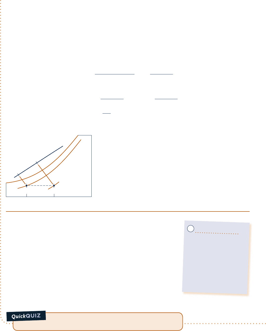
Alternative Psychrometric Chart Solution: Let us consider an alternative solution using the psychrometric chart.
As shown on the sketch of the psychrometric chart, Fig. E12.10b, the state of the moist air at the inlet is defined
by f
1
5 80% and a dry-bulb temperature of 108C. From the solution to part (a), we know that the humidity
ratio has the same value at the exit as at the inlet. Accordingly, the state of the moist air at the exit is fixed by
c12IdealGasMixtureandPsychromet744 Page 744 6/29/10 11:57:36 AM user-s146 c12IdealGasMixtureandPsychromet744 Page 744 6/29/10 11:57:36 AM user-s146 /Users/user-s146/Desktop/Merry_X-Mas/New/Users/user-s146/Desktop/Merry_X-Mas/New
12.8 Analyzing Air-Conditioning Processes 745
Mixture enthalpy
10°C30°C
Dry-bulb temperature
= 100%
φ
= 80%
φ
12
ω
2
=
ω
1
ω
Fig. E12.10b
Using the psychrometric chart, what is the dew point tempera-
ture, in 8C, for the moist air entering? At the exit? Ans.
<
78C, same.
v
2
5 v
1
and a dry-bulb temperature of 308C. By inspection of Fig. A-9, the relative humidity at the duct exit is
about 23%, and thus in agreement with the result of part (b).
The rate of heat transfer can be evaluated from the psychrometric chart using the following expression
obtained by rearranging Eq. (a) of part (a) to read
Q
#
cv
5 m
#
a
31h
a
1 vh
v
2
2
2 1h
a
1 vh
v
2
1
4 (b)
To evaluate Q
#
cv
from this expression requires values for the mixture enthalpy per unit mass of dry air (h
a
1 vh
v
)
at the inlet and exit. These can be determined by inspection of the psychrometric chart, Fig. A-9, as (h
a
1 vh
v
)
1
5
25.7 kJ/kg(dry air), (h
a
1 vh
v
)
2
5 45.9 kJ/kg(dry air).
Using the specific volume value y
a1
at the inlet state read from the chart together with the given volumetric
flow rate at the inlet, the mass flow rate of the dry air is found as
m
#
a
5
150 m
3
/
min
0.81 m
3
/
kg
1
dry air
2
5 185
kg1dry air
2
min
Substituting values into the energy rate balance, Eq. (b), we get
Q
#
cv
5 185
kg
1
dry air
2
min
145.9 2 25.72
kJ
kg
1
dry air
2
5 3737
kJ
min
which agrees closely with the result obtained in part (a), as expected.
➊
The first underlined term in this equation for Q
#
cv
is evaluated with specific
enthalpies from the ideal gas table for air, Table A-22. Steam table data are used
to evaluate the second underlined term. Note that the different datums for
enthalpy underlying these tables cancel because each of the two terms involves
enthalpy differences only. Since the specific heat c
pa
for dry air varies only slightly
over the interval from 10 to 308C (Table A-20), the specific enthalpy change of
the dry air could be evaluated alternatively with c
pa
5 1.005 kJ/kg ? K.
➋
No water is added or removed as the moist air passes through the duct at
constant pressure; accordingly, the humidity ratio v and the partial pressures
p
v
and p
a
remain constant. However, because the saturation pressure
increases as the temperature increases from inlet to exit, the relative humid-
ity decreases: f
2
, f
1
.
➌
The mixture pressure, 1 bar, differs slightly from the pressure used to construct
the psychrometric chart, 1 atm. This difference is ignored.
Ability to…
❑
apply psychrometric termi-
nology and principles.
❑
apply mass and energy bal-
ances for heating at con-
stant composition in a con-
trol volume at steady state.
❑
retrieve necessary property
data.
✓
Skills Developed
➌
c12IdealGasMixtureandPsychromet745 Page 745 6/29/10 11:57:39 AM user-s146 c12IdealGasMixtureandPsychromet745 Page 745 6/29/10 11:57:39 AM user-s146 /Users/user-s146/Desktop/Merry_X-Mas/New/Users/user-s146/Desktop/Merry_X-Mas/New
746 Chapter 12 Ideal Gas Mixture and Psychrometric Applications
12.8.3 Dehumidification
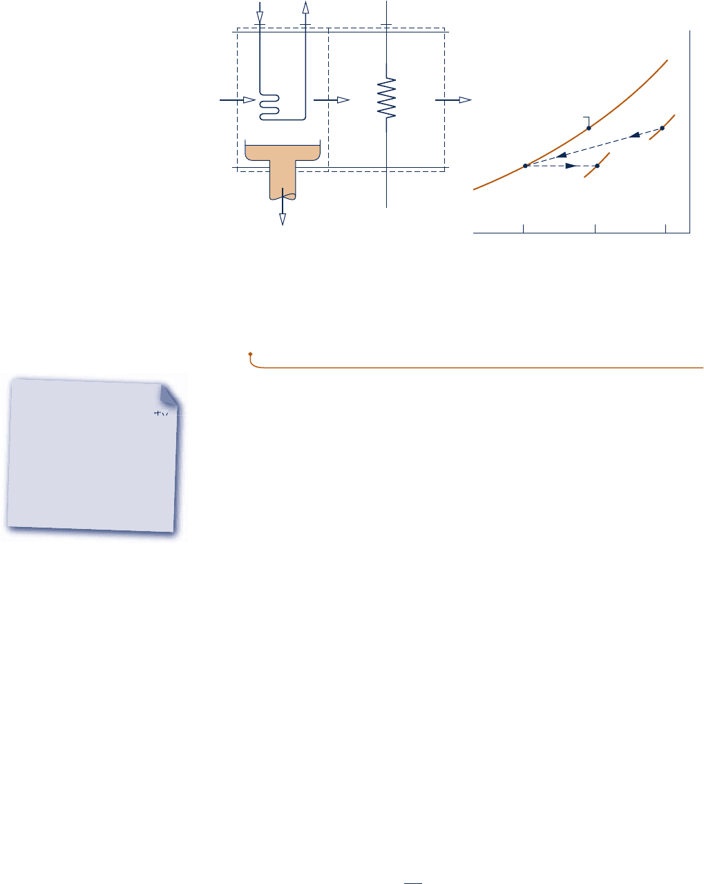
When a moist air stream is cooled at constant mixture pressure to a temperature below
its dew point temperature, some condensation of the water vapor initially present will
occur. Figure 12.11 shows the schematic of a dehumidifier using this principle. Moist
air enters at state 1 and flows across a cooling coil through which a refrigerant or
chilled water circulates. Some of the water vapor initially present in the moist air
condenses, and a saturated moist air mixture exits the dehumidifier section at state 2.
Although water condenses at various temperatures, the condensed water is assumed
to be cooled to T
2
before it exits the dehumidifier. Since the moist air leaving the
humidifier is saturated at a temperature lower than the temperature of the moist air
entering, the moist air stream at state 2 might be uncomfortable for direct use in occu-
pied spaces. However, by passing the stream through a following heating section, it can
be brought to a condition—state 3—most occupants would regard as comfortable.
Let us sketch the procedure for evaluating the rates at which condensate exits and
refrigerant circulates. This requires the use of mass and energy rate balances for the
dehumidifier section. They are developed next.
Mass Balance
The mass flow rate of the condensate m
#
w
can be related to the mass flow rate of the
dry air m
#
a
by applying conservation of mass separately for the dry air and water pass-
ing through the dehumidifier section. At steady state
m
#
a1
5 m
#
a2
(dry air)
m
#
v1
5 m
#
w
1 m
#
v2
(water)
The common mass flow rate of the dry air is denoted as m
#
a
. Solving for the mass flow
rate of the condensate
m
#
w
5 m
#
v1
2 m
#
v2
Introducing m
#
v1
5 v
1
m
#
a
and m
#
v2
5 v
2
m
#
a
, the amount of water condensed per unit
mass of dry air passing through the device is
m
#
w
m
#
a
5 v
1
2 v
2
Initial dew
point
= 100%
φ
2
3
1
3
φ
1
φ
ω
T
2
T
3
T
1
Dry-bulb temperature
Cooling
coil
m
r
·
1
ie 32
Heating
coil
2
= 100%
2
< T
1
2
<
1
ω
φ
T
ω
T
3
> T
2
ω
3
=
ω
2
m
w
·
Condensate –
saturated at T
2
(Dehumidifier section) (Heating section)
(a)(b)
Moist air
m
a
,
T
1
,
1
,
p = 1 atm
ω
·
Fig. 12.11 Dehumidification. (a) Equipment schematic. (b) Psychrometric chart representation.
TAKE NOTE...
A dashed line on a property
diagram signals only that
a process has occurred
between initial and final
equilibrium states, and
does not define a path for
the process.
c12IdealGasMixtureandPsychromet746 Page 746 7/23/10 7:06:33 PM user-s146 c12IdealGasMixtureandPsychromet746 Page 746 7/23/10 7:06:33 PM user-s146 /Users/user-s146/Desktop/Merry_X-Mas/New/Users/user-s146/Desktop/Merry_X-Mas/New

This expression requires the humidity ratios v
1
and v
2
. Because no moisture is added
or removed in the heating section, it can be concluded from conservation of mass
that v
2
5 v
3
, so v
3
can be used in the above equation in place of v
2
.
Energy Balance
The mass flow rate of the refrigerant through the cooling coil m
#
r
can be related to
the mass flow rate of the dry air m
#
a
by means of an energy rate balance applied to the
dehumidifier section. With W
#
cv
5 0, negligible heat transfer with the surroundings,
and no significant kinetic and potential energy changes, the energy rate balance
reduces at steady state to
0 5 m
#
r
1
h
i
2 h
e
2
1
1
m
#
a
h
a1
1 m
#
v1
h
v1
2
2 m
#
w
h
w
2
1
m
#
a
h
a2
1 m
#
v2
h
v2
2
where h
i
and h
e
denote the specific enthalpy values of the refrigerant entering and
exiting the dehumidifier section, respectively. Introducing m
#
v1
5 v
1
m
#
a
, m
#
v2
5 v
2
m
#
a
,
and m
#
w
5
1
v
1
2 v
2
2
m
#
a
0 5 m
#
r
1
h
i
2 h
e
2
1 m
#
a
31
h
a1
2 h
a2
2
1 v
1
h
g1
2 v
2
h
g2
2
1
v
1
2 v
2
2
h
f2
4
where the specific enthalpies of the water vapor at 1 and 2 are evaluated at the
saturated vapor values corresponding to T
1
and T
2
, respectively. Since the condensate
is assumed to exit as a saturated liquid at T
2
, h
w
5 h
f2
. Solving for the refrigerant
mass flow rate per unit mass of dry air flowing through the device
m
#
r
m
#
a
5
1
h
a1
2 h
a2
2
1 v
1
h
g1
2 v
2
h
g2
2
1
v
1
2 v
2
2
h
f2
h
e
2 h
i
The accompanying psychrometric chart, Fig. 12.11b, illustrates important features
of the processes involved. As indicated by the chart, the moist air first cools from
state 1, where the temperature is T
1
and the humidity ratio is v
1
, to state 2, where
the mixture is saturated (f
2
5 100%), the temperature is T
2
, T
1
, and the humidity
ratio is v
2
, v
1
. During the subsequent heating process, the humidity ratio remains
constant, v
2
5 v
3
, and the temperature increases to T
3
. Since all states visited are not
equilibrium states, these processes are indicated on the psychrometric chart by dashed
lines.
The example that follows provides an illustration involving dehumidification where
one of the objectives is the refrigerating capacity of the cooling coil.
Assessing Dehumidifier Performance
c c c c EXAMPLE 12.11 c
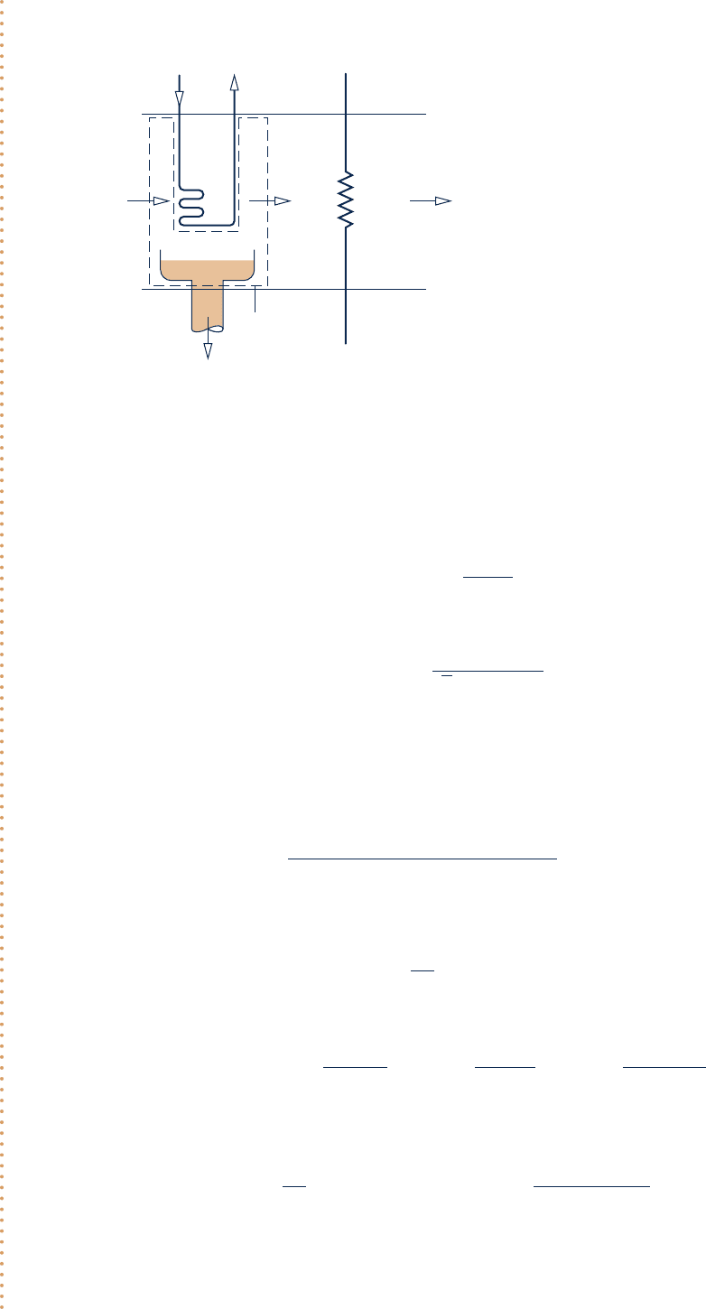
Moist air at 308C and 50% relative humidity enters a dehumidifier operating at steady state with a volumet-
ric flow rate of 280 m
3
/min. The moist air passes over a cooling coil and water vapor condenses. Condensate
exits the dehumidifier saturated at 108C. Saturated moist air exits in a separate stream at the same tem-
perature. There is no significant loss of energy by heat transfer to the surroundings and pressure remains
constant at 1.013 bar. Determine (a) the mass flow rate of the dry air, in kg/min, (b) the rate at which water
is condensed, in kg per kg of dry air flowing through the control volume, and (c) the required refrigerating
capacity, in tons.
SOLUTION
Known:
Moist air enters a dehumidifier at 308C and 50% relative humidity with a volumetric flow rate of 280 m
3
/min.
Condensate and moist air exit in separate streams at 108C.
Determine: Find the mass flow rate of the dry air, in kg/min, the rate at which water is condensed, in kg per kg
of dry air, and the required refrigerating capacity, in tons.
12.8 Analyzing Air-Conditioning Processes 747
c12IdealGasMixtureandPsychromet747 Page 747 6/29/10 11:57:46 AM user-s146 c12IdealGasMixtureandPsychromet747 Page 747 6/29/10 11:57:46 AM user-s146 /Users/user-s146/Desktop/Merry_X-Mas/New/Users/user-s146/Desktop/Merry_X-Mas/New
748 Chapter 12 Ideal Gas Mixture and Psychrometric Applications
Schematic and Given Data:
Analysis:
(a)
At steady state, the mass flow rates of the dry air entering and exiting are equal. The common mass flow
rate of the dry air can be determined from the volumetric flow rate at the inlet
m
#
a
5
1AV2
1
y
a1
The specific volume of the dry air at inlet 1, y
a1
, can be evaluated using the ideal gas equation of state, so
m
#
a
5
1AV2
1
1R
/
M
a
21T
1
/
p
a1
2
The partial pressure of the dry air p
a1
can be determined from p
a1
5 p
1
2 p
v1
. Using the relative humidity at the
inlet f
1
and the saturation pressure at 308C from Table A-2
p
v1
5 f
1
p
g1
5 10.5210.0424625 0.02123 bar
Thus, p
a1
5 1.013 2 0.02123 5 0.99177 bar. Inserting values into the expression for m
#
a
gives
m
#
a
5
1280 m
3
/
min210.99177 3 10
5
N
/
m
2
2
18314
/
28.97 N ? m
/
kg ? K21303 K2
5 319.35 kg
/
min
(b) Conservation of mass for the water requires m
#
v1
5 m
#
v2
1 m
#
w
. With m
#
v1
5 v
1
m
#
a
and m
#
v2
5 v
2
m
#
a
, the rate at
which water is condensed per unit mass of dry air is
m
#
w
m
#
a
5 v
1
2 v
2
The humidity ratios v
1
and v
2
can be evaluated using Eq. 12.43. Thus, v
1
is
v
1
5 0.662 a
p
v1
p
1
2 p
v1
b5 0.622a
0.02123
0.99177
b5 0.0133
kg1vapor
2
kg1dry air2
Since the moist air is saturated at 108C, p
v2
equals the saturation pressure at 108C: p
g
5 0.01228 bar from Table
A-2. Equation 12.43 then gives v
2
5 0.0076 kg(vapor)/kg(dry air). With these values for v
1
and v
2
m
#
w
m
#
a
5 0.0133 2 0.0076 5 0.0057
kg1conde
nsate2
kg1dry air2
Heating coilCooling coil
Condensate,
saturated at
T
2
= 10°C
Control volume
13 2
Saturated
mixture
10°
C
(AV)
1
T
1
1
= 280 m
3
/min
= 30°C
= 50%
φ
Fig. E12.11a
Engineering Model:
1.
The control volume shown in the accompanying fig-
ure operates at steady state. Changes in kinetic and
potential energy can be neglected, and W
#
cv
5 0.
2. There is no significant heat transfer to the sur-
roundings.
3. The pressure remains constant throughout at
1.013 bar.
4. At location 2, the moist air is saturated. The con-
densate exits at location 3 as a saturated liquid at
temperature T
2
.
5. The moist air streams are regarded as ideal gas
mixtures adhering to the Dalton model.
c12IdealGasMixtureandPsychromet748 Page 748 6/29/10 11:57:47 AM user-s146 c12IdealGasMixtureandPsychromet748 Page 748 6/29/10 11:57:47 AM user-s146 /Users/user-s146/Desktop/Merry_X-Mas/New/Users/user-s146/Desktop/Merry_X-Mas/New

(c) The rate of heat transfer
Q
#
cv
between the moist air stream and the refrigerant coil can be determined
using an energy rate balance. With assumptions 1 and 2, the steady-state form of the energy rate balance
reduces to
0 5 Q
#
cv
1 1m
#
a
h
a1
1 m
#
v1
h
v1
22 m
#
w
h
w
2 1m
#
a
h
a2
1 m
#
v2
h
v2
2 (a)
With m
#
v1
5 v
1
m
#
a
, m
#
v2
5 v
2
m
#
a
, and m
#
w
5 1v
1
2 v
2
2m
#
a
, this becomes
Q
#
cv
5 m
#
a
31h
a2
2 h
a1
22 v
1
h
g1
1 v
2
h
g2
1 1v
1
2 v
2
2h
f2
4 (b)
which agrees with Eq. 12.55. In Eq. (b), the specific enthalpies of the water vapor at 1 and 2 are evaluated at
the saturated vapor values corresponding to T
1
and T
2
, respectively, and the specific enthalpy of the exiting
condensate is evaluated as h
f
at T
2
. Selecting enthalpies from Tables A-2 and A-22, as appropriate, Eq. (b)
reads
Q
#
cv
5 1319.35231283.1 2 303.222 0.013312556.321 0.007612519.821 0.0057142.0124
5211,084 kJ
/
min
Since 1 ton of refrigeration equals a heat transfer rate of 211 kJ/min (Sec. 10.2.1), the required refrigerating
capacity is 52.5 tons.
Alternative Psychrometric Chart Solution: Let us consider an alternative solution using the psychrometric chart.
As shown on the sketch of the psychrometric chart, Fig. E12.11b, the state of the moist air at the inlet 1 is defined
by f 5 50% and a dry-bulb temperature of 308C. At 2, the moist air is saturated at 108C. Rearranging Eq. (a),
we get
Q
#
cv
5 m
#
a
31
h
a
1 vh
v
2
2
2
1
h
a
1 vh
v
2
1
1 1v
1
2 v
2
2h
w
4 (c)
The underlined terms and humidity ratios, v
1
and v
2
, can be read directly from the chart. The mass flow rate of
the dry air can be determined using the volumetric flow rate at the inlet and y
a1
read from the chart. The specific
enthalpy h
w
is obtained (as above) from Table A-2: h
f
at T
2
. The details are left as an exercise.
Using the psychrometric chart, determine the wet-bulb tem-
perature of the moist air entering the dehumidifier, in °C. Ans.
<
22°C.
Specific enthalpy
of moist air, in
kJ/kg(dry air)
f = 50%
f = 100%
10°C
Dr
y
-bulb temperature
30°C
(h
a
+ w h
v
)
1
(h
a
+ w h
v
)
2
w
2
w
1
w
1
2
Fig. E12.11b
12.8 Analyzing Air-Conditioning Processes 749
Ability to…
❑
apply psychrometric termi-
nology and principles.
❑
apply mass and energy
balances for a dehumidifica-
tion process in a control
volume at steady state.
❑
retrieve property data for
dry air and water.
❑
apply the psychrometric
chart.
✓
Skills Developed
c12IdealGasMixtureandPsychromet749 Page 749 7/23/10 7:06:46 PM user-s146 c12IdealGasMixtureandPsychromet749 Page 749 7/23/10 7:06:46 PM user-s146 /Users/user-s146/Desktop/Merry_X-Mas/New/Users/user-s146/Desktop/Merry_X-Mas/New
750 Chapter 12 Ideal Gas Mixture and Psychrometric Applications
Analyzing a Steam-Spray Humidifier
c c c c EXAMPLE 12.12 c
Moist air with a temperature of 228C and a wet-bulb temperature of 98C enters a steam-spray humidifier. The
mass flow rate of the dry air is 90 kg/min. Saturated water vapor at 1108C is injected into the mixture at a rate
of 52 kg/h. There is no heat transfer with the surroundings, and the pressure is constant throughout at 1 bar.
Using the psychrometric chart, determine at the exit (a) the humidity ratio and (b) the temperature, in 8C.
SOLUTION
Known:
Moist air enters a humidifier at a temperature of 228C and a wet-bulb temperature of 98C. The mass flow
rate of the dry air is 90 kg/min. Saturated water vapor at 1108C is injected into the mixture at a rate of 52 kg/h.
Find: Using the psychrometric chart, determine at the exit the humidity ratio and the temperature, in 8C.
Schematic and Given Data:
Moist air
T
2
= ?
2
= ?
ω
3
m
a
=
90 kg/min
·
T
1
= 22°C
T
wb
= 9°C
Saturated water vapor
at 110°C, m
st
= 52 kg/h
·
Boundary
12
Fig. E12.12a
Engineering Model:
1.
The control volume shown in the accompanying figure oper-
ates at steady state. Changes in kinetic and potential energy
can be neglected and W
#
cv
5 0.
2. There is no heat transfer with the surroundings.
3. The pressure remains constant throughout at 1 bar. Figure A-9
remains valid at this pressure.
4. The moist air streams are regarded as ideal gas mixtures adher-
ing to the Dalton model.
12.8.4 Humidification
It is often necessary to increase the moisture content of the air circulated through
occupied spaces. One way to accomplish this is to inject steam. Alternatively, liquid
water can be sprayed into the air. Both cases are shown schematically in Fig. 12.12a.
The temperature of the moist air as it exits the humidifier depends on the condition
of the water introduced. When relatively high-temperature steam is injected, both the
humidity ratio and the dry-bulb temperature are increased. This is illustrated by the
accompanying psychrometric chart of Fig. 12.12b. If liquid water is injected instead of
steam, the moist air may exit the humidifier with a lower temperature than at the inlet.
This is illustrated in Fig. 12.12c. The example to follow illustrates the case of steam
injection. The case of liquid water injection is considered further in the next section.
T
2
> T
1
2
>
ω
1
ω
T
2
< T
1
2
>
ω
1
ω
2
2
1
1
ωω
Dry-bulb temperatureDry-bulb temperature
Moist air
T
1
,
1
ω
Moist air
T
2
,
2
>
1
ωω
12
Water injected
(vapor or liquid)
(a)(b)(c
)
Fig. 12.12 Humidification. (a) Control volume. (b) Steam injected. (c) Liquid injected.
c12IdealGasMixtureandPsychromet750 Page 750 6/29/10 11:57:54 AM user-s146 c12IdealGasMixtureandPsychromet750 Page 750 6/29/10 11:57:54 AM user-s146 /Users/user-s146/Desktop/Merry_X-Mas/New/Users/user-s146/Desktop/Merry_X-Mas/New

Analysis:
(a)
The humidity ratio at the exit v
2
can be found from mass rate balances on the dry air and water individually. Thus
m
#
a1
5 m
#
a2
1dry air2
m
#
v1
1 m
#
st
5 m
#
v2
1water2
With m
#
v1
5 v
1
m
#
a
, and m
#
v2
5 v
2
m
#
a
, where m
#
a
is the mass flow rate of the air, the second of these becomes
v
2
5 v
1
1
m
#
st
m
#
a
Using the inlet dry-bulb temperature, 228C, and the inlet wet-bulb temperature, 98C, the value of the humidity ratio
v
1
can be found by inspection of the psychrometric chart, Fig. A-9. The result is v
1
5 0.002 kg (vapor)/kg(dry air).
This value should be verified as an exercise. Inserting values into the expression for v
2
v
2
5 0.002 1
152 kg
/
h2
Z
1 h
/
60 min
Z
90 kg
/
min
5 0.0116
k
g1vapor2
kg1dry air2
(b) The temperature at the exit can be determined using an energy rate balance. With assumptions 1 and 2, the
steady-state form of the energy rate balance reduces to a special case of Eq. 12.55. Namely
0 5 h
a1
2 h
a2
1 v
1
h
g1
1 1v
2
2 v
1
2h
g3
2 v
2
h
g2
(a)
In writing this, the specific enthalpies of the water vapor at 1 and 2 are evaluated as the respective saturated vapor
values, and h
g3
denotes the enthalpy of the saturated vapor injected into the moist air.
Equation (a) can be rearranged in the following form suitable for use with the psychrometric chart.
➊
1h
a
1 vh
g
2
2
5 1h
a
1 vh
g
2
1
1 1v
2
2 v
1
2h
g3
(b)
As shown on the sketch of the psychrometric chart, Fig. E12.12b, the first term on the right of Eq. (b) can be obtained
from Fig. A-9 at the inlet state, defined by the intersection of the inlet dry-bulb temperature, 228C, and the inlet wet-bulb
temperature, 98C; the value is 27.2 kJ/kg(dry air). The second term on the right can be evaluated using the known humid-
ity ratios v
1
and v
2
and h
g3
from Table A-2: 2691.5 kJ/kg(vapor). The value of the second term of Eq. (b) is 25.8 kJ/kg
(dry air). The state at the exit is then fixed by v
2
and (h
a
1 vh
g
)
2
5 53 kJ/kg(dry air), calculated from the two values
just determined. Finally, the temperature at the exit can be read directly from the chart. The result is T
2
< 23.58C.
Specific enthalpy of moist air,
in kJ/kg(dry air)
T
2
= 23.5°C
(h
a
+ w h
g
)
2
= 53 kJ/kg(dry air)
T
wb
= 9°C
w
1
w
2
w
T
1
= 22°C
1
2
(h
a
+ w h
g
)
1
= 27.2 kJ/kg(dry air)
Fig. E12.12b
Alternative IT Solution:
➋
The following program allows T
2
to be determined using IT, where m
#
a
is denoted as mdota, m
#
st
is denoted as
mdotst, w1 and w2 denote v
1
and v
2
, respectively, and so on.
12.8 Analyzing Air-Conditioning Processes 751
c12IdealGasMixtureandPsychromet751 Page 751 7/23/10 7:06:57 PM user-s146 c12IdealGasMixtureandPsychromet751 Page 751 7/23/10 7:06:57 PM user-s146 /Users/user-s146/Desktop/Merry_X-Mas/New/Users/user-s146/Desktop/Merry_X-Mas/New

752 Chapter 12 Ideal Gas Mixture and Psychrometric Applications
// Given data
T1 5 22 // 8C
Twb1 5 9 // 8C
mdota 5 90 // kg/min
p 5 1 // bar
Tst 5 110 // 8C
mdotst 5 (52 / 60) // converting kg/h to kg/min
// Evaluate humidity ratios
w1 5 w_TTwb (T1,Twb1,p)
w2 5 w1 1 (mdotst / mdota)
// Denoting the enthalpy of moist air at state 1 by
// h1, etc., the energy balance, Eq. (a), becomes
0 5 h1 2 h2 1 (w2 2 w1)*hst
// Evaluate enthalpies
h1 5 ha_Tw(T1,w1)
h2 5 ha_Tw(T2,w2)
hst 5 hsat_Px(“Water/Steam”,psat,1)
psat 5 Psat_T(“Water/Steam ”,Tst)
Using the Solve button, the result is T
2
5 23.48C, which agrees closely with the
values obtained above, as expected.
➊
A solution of Eq. (b) using data from Tables A-2 and A-22 requires an
iterative (trial) procedure. The result is T
2
5 248C, as can be verified.
➋
Note the use of special Moist Air functions listed in the Properties menu of IT.
Using the psychrometric chart, what is the relative humidity
at the exit? Ans.
<
63%.
TAKE NOTE...
Evaporative cooling takes
place at a nearly constant
wet-bulb temperature.
12.8.5 Evaporative Cooling
Cooling in hot, relatively dry climates can be accomplished by evaporative cooling.
This involves either spraying liquid water into air or forcing air through a soaked pad
that is kept replenished with water, as shown in Fig. 12.13. Owing to the low humid-
ity of the moist air entering at state 1, part of the injected water evaporates. The
energy for evaporation is provided by the air stream, which is reduced in temperature
and exits at state 2 with a lower temperature than the entering stream. Because the
incoming air is relatively dry, the additional moisture carried by the exiting moist air
stream is normally beneficial.
For negligible heat transfer with the surroundings, no work W
#
cv
, and no significant
changes in kinetic and potential energy, the steady-state forms of the mass and
energy rate balances reduce for the control volume of Fig. 12.13a to this special case
of Eq. 12.55:
1h
a2
1 v
2
h
g2
25
1
v
2
2 v
1
2
h
f
1 1h
a1
1 v
1
h
g1
2
where h
f
denotes the specific enthalpy of the liquid stream entering the control
volume. All the injected water is assumed to evaporate into the moist air stream.
The underlined term accounts for the energy carried in with the injected liquid
water. This term is normally much smaller in magnitude than either of the two moist
air enthalpy terms. Accordingly, the enthalpy of the moist air varies only slightly, as
illustrated on the psychrometric chart of Fig. 12.13b. Recalling that lines of constant
Ability to…
❑
apply psychrometric termi-
nology and principles.
❑
apply mass and energy
balances for a spray humidi-
fication process in a control
volume at steady state.
❑
retrieve necessary property
data using the psychromet-
ric chart.
❑
apply IT for psychrometric
analysis.
✓
Skills Developed
c12IdealGasMixtureandPsychromet752 Page 752 6/30/10 8:18:46 PM user-s146 c12IdealGasMixtureandPsychromet752 Page 752 6/30/10 8:18:46 PM user-s146 /Users/user-s146/Desktop/Merry_X-Mas/New/Users/user-s146/Desktop/Merry_X-Mas/New
