Messerschmidt U. Dislocation Dynamics During Plastic Deformation
Подождите немного. Документ загружается.


282 8 Metallic Alloys
shorter ageing times are under-aged, while those with longer ageing times are
over-aged.
In several aluminium alloys, the particle microstructures are very well stud-
ied so that the yield stresses of the materials can be modeled by the theories
discussed in Sects. 4.5 and 4.7. However, by applying conventional methods,
one often cannot decide whether the precipitates considered are the relevant
obstacles to dislocation glide controlling the flow stress or not. In situ strain-
ing experiments in an HVEM, which reveal the morphology and kinematics
of the dislocations overcoming the particles, may help answer these questions.
The relevant obstacles need not have the density and strength analyzed by
other methods. The quantitative data that can be obtained from the in situ
experiments are used to check the predictions of the models.
8.1.1 Al–Zn–Mg
The alloy Al-4.54 wt% Zn-1.18 wt% Mg is a material for technical application.
For the described experiments [226], specimens were heat treated to grow
particles of the η
phase which are large enough to be imaged in the HVEM
as small dark dots shown before in Fig. 4.30. These semicoherent particles
are supposed to be visible mainly due to structure factor contrast. Under the
imaging condition with higher-order reflections, almost all particles should be
visible, and the size of the contrast dots should correspond to the extensions
of the particles. The particles have an average diameter of D =10.5nm and
an average volume of V =1.06 × 10
−24
m
3
. They fill a fraction of f =0.33%
of the volume. Considering the disc shape of the particles, this is by a factor
of more than 10 less than the atomic concentration of the Zn and Mg being
added. As a measure of the obstacle density, the square lattice distance defined
in (4.48) can be calculated by
l
th
sq
=
π/(6f ) D. (8.1)
From the above data, it follows that l
sq
= 170 nm.
The in situ straining experiments (Fig. 4.30) show dislocations pinned at
localized obstacles and strongly bowing out between them. These configura-
tions correspond to the so-called stress determining configurations mentioned
in the theory in Sect. 4.5. For measuring the obstacle distances, all cusps in
the dislocation lines are considered. The distances obey the typical asymmet-
ric shape of the theoretical distribution of Fig. 7.10 with an average value
of l = 62 nm. Effective stresses were determined from the curvature of the
bowed-out dislocation segments using the loop fitting method described in
Sect. 7.2.2, yielding the reciprocal major half-axis S = e
−1
=16μm
−1
of the
fitting ellipses as well as the effective stress τ
∗
according to (7.3). In con-
trast to the evaluation for MgO, where curvature data were determined from
all segments, only clearly imaged segments were selected in the aluminium
alloys, because of the reduced quality of the dislocation images due to the
8.1 Precipitation Hardened Aluminium Alloys 283
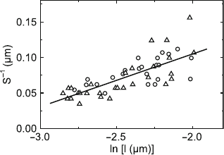
Fig. 8.1. Dependence of the dislocation bowing S on the logarithm of the segment
length l in Al–Zn–Mg. Data from [115]
superposition of the contrasts of the precipitates. This selection of segments
will certainly prefer strongly bowed segments, leading to higher values of τ
∗
.
The dependence of the dislocation curvature on the logarithm of the segment
length, predicted by the theory in Sect. 3.2.7, was proved also for this alloy,
as illustrated in Fig. 8.1. The constant in (3.45) amounts to C = −4.6, in
agreement with the results for MgO. Nevertheless, the theoretical constant
C = −1.61 was used for the evaluations. These methodical remarks hold also
for the other aluminium alloys discussed later.
With (7.6), it follows from l and S that l
sq
=60nm≈ l. Accordingly, the
square lattice distance measured directly at the pinned dislocations l
sq
is only
one third of the value l
th
sq
following from the concentration and size of the pre-
cipitates visible in the electron microscope. This means that the dislocations
“feel” about ten times more obstacles than the η
particles. The latter grow
from Guinier–Preston zones, which are still present in the material. They are
strong obstacles due to their stress field but they are not visible in the HVEM
micrographs. They were not considered important before the in situ experi-
ments were carried out. As the dislocations move very jerkily over distances
long compared to the obstacle distances, most of the dislocation configura-
tions are unstable or j ≈ 1 in Fig. 4.18. As a consequence, the normalized
stress τ
following from the dislocation curvature is only slightly lower than
the athermal strength τ
0
of the obstacle array. The overcoming of the obsta-
cles is then more or less of athermal nature. The obstacle data, together with
the data of the other Al alloys, are summarized in [115] and in Table 8.1. The
values of the effective stress τ
∗
are partly very high owing to the theoretical
value of the constant C = −1.61 used in (3.45). It may be concluded from
the in situ experiments on the Al–Zn–Mg alloy that the concentration of the
precipitates is strongly underestimated from the size and density of particles
visible in the electron micrographs. The obstacles are quite strong and are
overcome in an athermal way.
The flow stress component from precipitation hardening is certainly not
the only contribution to the flow stress of the order of magnitude of σ =
200 MPa. A stress component due to Taylor hardening from long-range
284 8 Metallic Alloys
elastic interactions between dislocations is estimated via (5.11) to amount to
τ
i
≈ 25 MPa at a dislocation density of 5 × 10
13
m
−2
. Further information on
the deformation processes can be inferred from the macroscopic deformation
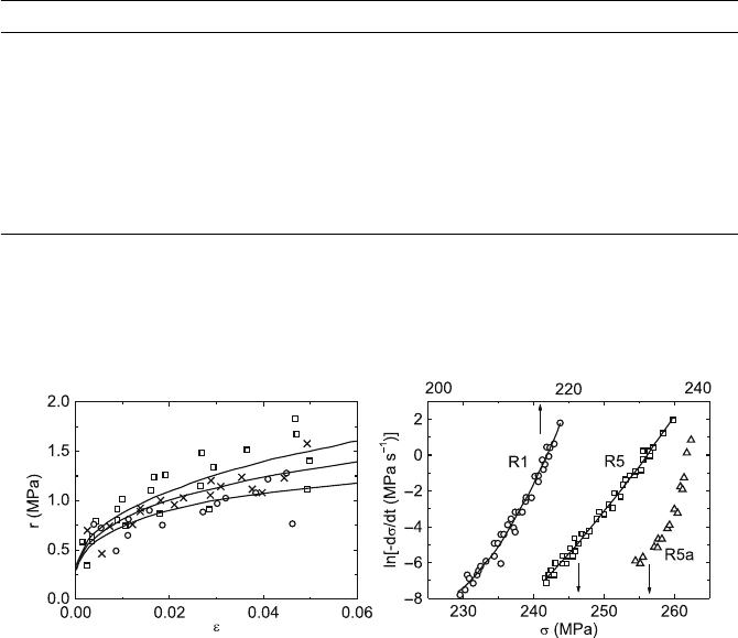
properties. Figure 8.2a presents the dependence of the strain rate sensitivity
r measured by strain rate cycling tests on the strain, with the strain rate
as a parameter. In general, the r values of about 1 MPa are very low result-
ing in high stress exponents m
= σ/r, which are characteristic of athermal
deformation. The activation volume V of about 450 b
3
fits the segment length
of l ≈ 220 b, yielding an activation distance of Δd = V/(bl) ≈ 2 b.Ther
values show the usual increase with strain due to work hardening. The inter-
esting point is the inverse dependence on the strain rate, which also holds for
Table 8.1. Parameters characterizing the interaction between dislocations and
precipitates in Al alloys
Al–Zn–Mg Al–Ag, 6 h Al–Ag, 9 h Al–Li, leading disls.
l (nm) 62 111 117 56
S (μm
−1
) 16 11.2 14.9 17
l
sq
(nm) 60 ≈110 ≈110 53
l
th
sq
(nm), CTEM 170 ≈20 ≈20 34
τ
0.48 0.62 0.87 0.45
τ
∗
(MPa) with C = −1.61 59 45 60 59
estimated τ
0
0.5 0.65 0.9 0.5
C −4.6 −5.6
The lines are: segment length, reciprocal major half axis of ellipses fitting bowed-
out dislocation segments, square lattice distance from in situ experiments, square
lattice distance from conventional transmission electron microscopy (CTEM), nor-
malized effective stress, effective stress, normalized athermal strength of obstacle
array, constant in (3.45)
(a)
(b)
Fig. 8.2. Strain rate sensitivity of the Al–Zn–Mg alloy. Dependence of the strain
rate sensitivity measured by strain rate cycling tests on the strain with the strain
rate as parameter (a). ˙ε =4×10
−6
s
−1
(squares), 4×10
−5
s
−1
(crosses), 4×10
−4
s
−1
(circles). Stress relaxation curves (b). R5a is a repeated relaxation after R5. Data
from [226]
8.1 Precipitation Hardened Aluminium Alloys 285
the flow stress itself. This inverse dependence is also obvious from the course
of stress relaxation curves plotted in Fig. 8.2b, with their abnormal bending
away from the stress axis. As described in Sect. 4.11, the inverse dependence
of r on ˙ε may result from diffusion processes in the dislocation cores and
corresponds to range A in Fig. 4.39. These effects are also manifest as strain
ageing when the deformation machine is stopped and as the strong reduction
of the relaxation rate at the repeated relaxation R5a with respect to the orig-
inal relaxation R5. As described in Sect. 2.1, differences between an original
relaxation curve starting from continuous deformation and a repeated one
started before steady deformation is reached, again document changes in the
microstructure during the first relaxation. According to [452], a great part
of the additions remain in solution and can associate with vacancies [453] to
form mobile elastic dipoles, which may generate Snoek atmospheres around
the dislocations and contribute to the flow stress. Thus, the combined use of
microscopic and macroscopic methods is necessary to gain information on the
different processes controlling the flow stress.
8.1.2 Al–Ag
Al–Ag alloys are a model system to investigate the decomposition of super-
saturated binary alloys and the influence of the resulting obstacle spectra
on the mechanical properties. Very detailed studies have been performed on
the decomposition kinetics and the influence of the size and density of the
precipitates on the yield stress of an Al-1 at% Ag alloy isothermally aged at
413 K after a suitable solution treatment [454, 455]. As a result, the mate-
rial shows a remarkable anomaly of the ageing kinetics during 10 h, where a
primary increase in the flow stress is followed by a drop and a re-increase.
As the silver-rich particles have neither a marked lattice constant misfit nor
a modulus misfit, stacking fault hardening is considered the main strength-
ening mechanism [456]. The primary increase was interpreted on the basis
of the size and density of precipitates determined by high-resolution electron
microscopy [454]. However, in situ straining experiments in an HVEM [283]
showed that the basic assumption was not fulfilled that all precipitates visible
in the electron microscope represent the relevant obstacle spectrum.
The in situ study was aimed at observing differences in the dislocation
behavior between the under-aged state after ageing at 413 K for 6 h and the
peak-aged state after 9 h. The basic features of the dislocation structure during
in situ straining are shown in Fig. 8.3. Similar micrographs were obtained for
both ageing states. As in Al–Zn–Mg, the dislocations exhibit a curly shape,
bowing out between localized obstacles. Such micrographs allow the obstacle
distances l and l
sq
to be determined as well as the curvature data S and
τ
all listed in Table 8.1. Included in the table are also the square lattice
distances l
th
sq
calculated from high-resolution TEM. Different from Al–Zn–Mg,
the relevant obstacle distances along the dislocations are now about 5 times
larger than those predicted from the size and density of contrast dots in the
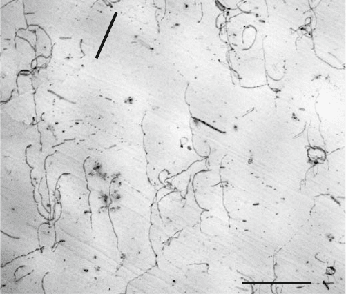
286 8 Metallic Alloys
1 µm
g
L
L
Fig. 8.3. Dislocation structure in an Al-1 at% Ag single crystal aged at 413 K for
9 h, taken during in situ deformation in an HVEM at room temperature. Dislocation
loops L. g = [600] parallel to tensile axis, (0
¯
11) foil normal. From the work in [283]
high-resolution micrographs. Thus, only part of the precipitates are active as
pinning points along the dislocations. While the square lattice distances are
almost equal for the two annealing states, the normalized stress for the peak-
aged state is clearly higher than that of the under-aged state. These stresses
are all very high, indicating that the precipitates are strong obstacles.
The dynamic behavior of the dislocations is demonstrated in the following
video clip.
Video 8.1. Dislocation motion in an Al-1 at% Ag single crystal at room tem-
perature: The clip consists of four short sequences of the same specimen area,
demonstrating the pinning of dislocations by the small precipitates. The dislocation
motion is very jerky over distances far longer than those between the precipitates.
Frequently, dislocation debris and larger dislocation loops are produced very sud-
denly. The appearance and disappearance of a large loop is indicated by a green
circle to the left of the site of the event.
As discussed for Al–Zn–Mg, the jerky motion over larger distances means that
τ
is only slightly smaller than the strength of the obstacle array τ
0
.
As mentioned earlier, stacking fault strengthening is widely accepted as the
main hardening mechanism in two-phase Al–Ag alloys [456,457]. Owing to the
difference between the stacking fault energies γ
sf
of aluminium (200 mJ m
−2
)
and silver (20 mJ m
−2
), a dislocation that encounters a (silver-rich) precipitate
will split into two partials enclosing a stacking fault. Following [456], the
contribution to the critical resolved shear stress τ
y
is given by

8.1 Precipitation Hardened Aluminium Alloys 287
τ
y
=
F
0
bl
=
Δγ
sf
d
bl
, (8.2)
with the quantities defined in Sect. 4.5 (F
0
maximum interaction force between
dislocation and precipitate, l mean distance between obstacles in the slip
plane). Δγ
sf
is the difference between the stacking-fault energies of the pre-
cipitate and the matrix, and d is the effective length of the dislocation in the
particle. The equation holds for the athermal surmounting of the obstacles,
which is in agreement with the large slip distances observed in the video clips.
The effective length d of the dislocation in the particle depends on the relation
between the particle radius and the splitting widths of the dislocation in the
matrix as well as in the particle.
The result of l
sq
≈ 5 l
th
sq
shows that the dislocations are not interacting with
all particles present. It seems likely that a small number of strong obstacles
governs the hardening behavior of this alloy. This view is supported by the
fact that the curvature of the dislocation segments between the obstacles can
explain the whole flow stress. It is well-known that the precipitates consist of
ε and η particles (e.g., [458]). Al-Kassab and Haasen [459] applied a field ion
microscope-atom probe to investigate an Al-3 at% Ag alloy, isothermally aged
at 413 K for different times. They found that, from early to intermediate stages
of decomposition, ε and η precipitates coexist with different concentrations of
silver atoms of 31 and 57%. It may be assumed that the silver-rich η precip-
itates control the flow stress. In a mixture of obstacles of different strengths,
the mean obstacle distance is determined mainly by the concentration of the
strong obstacles (Sect. 4.5.1).
Equation (8.2) can be used to estimate the difference Δγ
sf
between
the stacking-fault energies of the matrix and the precipitates. The follow-
ing parameters are applicable to the specimens aged for 6 h: d =2.3nm,
l = 110 nm, and τ
y
= 17 MPa from the macroscopic experiments [455]. This
results in Δγ
sf
= 240 mJ m
−2
, which is even larger than the stacking fault
energy of 200 mJ m
−2
for aluminium. On the other hand, the cutting planes
of the particles are, on the average, smaller than the particle diameter consid-
ered above. Thus, the obstacles observed in the in situ experiments seem to be
stronger than the usual models of stacking-fault strengthening can explain.
Possible explanations of this discrepancy are given in [283]. Because of the
low stacking fault energy in the particles, the stacking fault width should be
greater than the particle diameter. In this case, the stacking fault fills the
whole particle and the dislocation is fixed to the particle border. This results
in an additional elastic contribution to the interaction energy between particle
and dislocation [456].
8.1.3 Al–Li
Because of their light weight connected with high elastic stiffness and strength,
aluminium–lithium alloys are of considerable technical interest. They harden
288 8 Metallic Alloys
by precipitates of the ordered δ
phase by analogy with nickel base alloys
containing Ni
3
Al precipitates. The precipitates have the L1
2
structure. A dis-
location of the matrix with an a/2110 Burgers vector produces an antiphase
boundary (APB) in the particle. It can be removed when a second dislocation
of the same Burgers vector is passing. Thus, the second dislocation moving
exactly on the same slip plane is drawn into the particles with antiphase
boundaries. This opposes the elastic repulsion between the two dislocations.
Accordingly, it is energetically favorable if the dislocations move in pairs
leaving particles without faults on the cutting planes. The respective the-
ory [460–462] has originally been developed by Gleiter and Hornbogen and
is reviewed in [224]. Evaluations of particle distributions and macroscopic
measurements of the mechanical properties are given in [463–466].
Dislocation processes in single crystals grown from the commercial alloy
P53 from Alcan were observed in in situ straining experiments in an HVEM
[284, 467]. The single crystals contained 8.4 at% Li and were homogenized
at 843 K. Afterwards, precipitates of the δ
phase were grown by two-stage
annealing. The δ
particles were spherical, having an average diameter of
D =15.6 nm and a volume fraction of f =0.11. The alloy is then in the
under-aged state.
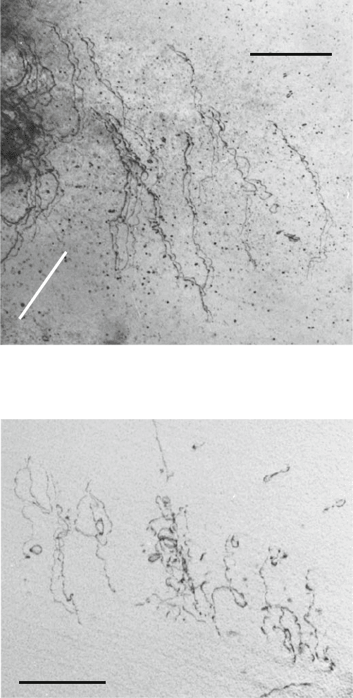
Figure 8.4 shows a typical dislocation structure. The dislocations move in
pairs, in accordance with other microstructural observations (e.g., [468]). The
leading dislocations of the pairs strongly bow out between pinning points. The
trailing dislocations are less strongly bowed, but also in forward direction. In
other parts of the specimens the dislocations move as single dislocations as
in Fig. 8.5. They also bow out between obstacles. In general, the dislocations
move very jerkily, usually over distances larger than a micrometer, which
indicates that the stress is close to the athermal strength of the obstacle array
(see Sect. 4.5.1, Fig. 4.18). Most dislocations show a loose arrangement, with
each dislocation or dislocation pair moving on an individual slip plane.
Quantitative data from dislocation pairs can be obtained from the micro-
graphs of dislocations under load using the model mentioned above and
outlined in Fig. 8.6. The leading dislocation 1 has to create the antiphase
boundaries inside the precipitates. It is driven by the applied stress τ and the
repulsive internal stress τ
i
arising from the trailing dislocation 2. Accordingly,
the following force balance holds
(τ + τ
i
) l
1
b − γ
APB
D
1
=0, (8.3)
where l
1
is the obstacle distance and D
1
the effective particle diameter along
the leading dislocation, and γ
APB
is the antiphase boundary energy.
The second dislocation is pushed forward by annihilating the antiphase
boundaries in the particles and backward by the internal stress. Thus,
(τ − τ
i
) l
2
b + γ
APB
D
2
=0. (8.4)
Theobstacledistancel
2
and the effective particle diameter D
2
generally differ
from the respective values of the leading dislocation. According to (3.24) and
8.1 Precipitation Hardened Aluminium Alloys 289
1 µm
TD
Fig. 8.4. Slip band of dislocation pairs in an Al-8.4 at% Li single crystal during in
situdeformationinanHVEMatroomtemperature. TD tensile direction. From the
work in [284]
1 µm
Fig. 8.5. Slip band of unpaired dislocations in an Al-8.4 at% Li single crystal during
in situ deformation in an HVEM at room temperature. From the work in [284]
290 8 Metallic Alloys
x
D
1
D
2
l
2
l
1
1
2
Fig. 8.6. Outline of the model of dislocation pairs in alloys with precipitates of an
ordered structure
with y
0
= 0, the internal stress between the dislocations of the pairs is given
by
τ
i
= μb/(2πx)
for screw dislocations, and by
τ
i
= μb/(2π[1 − ν]x)
for edge dislocations. Strictly speaking, these formulae hold only for straight
dislocations. x is the distance between the dislocations, which can be measured
from the micrographs.
Dislocation motion in pairs was simulated in Nimonic PE16, a material
strengthened in a way similar to the present Al–Li alloy by particles that have
to be cut by forming antiphase boundaries. The precipitates are also of the
L1
2
structure. The following video presents an example of the simulation by
V. Mohles performed in the group of E. Nembach at M¨unster University.
Video 8.2. Simulation of the motion of a dislocation pair in Nimonic PE16:
The video sequence presents the simulation of the motion of a pair of edge dis-
locations under conditions very similar to those in the in situ experiments on
Al-8.4 at% Li. The volume fraction of the precipitates amounts to f =0.089, the
radius of the particles is r =24b, and the normalized antiphase boundary energy
is g = γ
APB
/(bμ)=0.015. The simulation considers the obstacle resistance, the
interaction between the dislocations of the pair as well as the self-stress of the bow-
ing dislocation itself. In addition, viscous damping is included. a in the legend is
the fraction of the area swept. Details of the simulation method and some results
are given in [469]. The video shows the coupled motion of the (red) leading dis-
location and the (blue) trailing dislocation. As expected, the leading dislocation
strongly bows out while the trailing dislocation is quite smooth. The latter corre-
sponds to the model where the trailing dislocation is pushed forward by removing
the antiphase boundaries in the particles cut before by the leading dislocation. These
forward forces should be balanced by a slight backward curvature of the connected
dislocation segments in the matrix. However, this is in contrast to the experimental
observation that the trailing dislocations are bowed-out in forward direction, too.
Note that the normalized stress s =10
3
τ/μ, indicated in the legend, is raised by a
factor of almost two during the motion. If the critical (final) stress had acted right
from the beginning, the dislocations would have swept most of the area very quickly.
Nevertheless, the damped motion visible also in the last part of the video does not
correspond to the underdamped jerky motion in the experiments on Al–Li.

8.1 Precipitation Hardened Aluminium Alloys 291
Table 8.2. Interaction parameters of leading dislocations in pairs and single screw
dislocations with precipitates in Al-8.4 at% Li (Data from [284])
Disl. pairs Single screws
Screws Edges
l (nm) 58.9 52.7 53.6
S (μm
−1
) 17.5 16.5 18.5
l
sq
(nm) 57.5 47.5 51.5
1/x(μm
−1
) 19.1 18.3
τ
∗
(MPa) 62.7 55.3 68.0
τ
i
(MPa) 22.5 33.7
τ (MPa) 40.2 21.6
From the micrographs taken during the in situ experiments, the same
data as for the other aluminium alloys before were determined for the leading
dislocations of the pairs, separately for those of dominating screw and edge
character, as well as for unpaired screw dislocations. Details of the evaluation
are given in [284]. The results are listed in Table 8.2. In Sect. 8.1.1, the data
of Table 8.1 are averages of the values of screws and edges. The present alloy
shows also the dependence of the dislocation curvature on the logarithm of
the segment length as predicted in (3.45) and proved for MgO and Al–Zn–
Mg. The constant C is included in Table 8.1 and fits the values of the other
materials.
Using (8.1), a theoretical value of the square lattice distance can again
be calculated from the average particle diameter and volume fraction cited
above, yielding l
th
sq
= 34 nm, which is in relatively good agreement with the
measurements from the in situ experiments.
In the force balance (8.3), all parameters are known except the antiphase
boundary energy γ
APB
and D
1
. As the dislocations do not cut all the parti-
cles at the equator, the effective diameter may be D
1
= πD/4, where D is
the average diameter of the spherical particles. Using the same value for D
as above, it follows that D
1
=11.8nm. For γ
APB
, this yields 0.090 J m
−2
for
screw dislocations, and 0.071 J m
−2
for dislocations with a large edge compo-
nent. These values are remarkably smaller than the literature values of about
0.15 J m
−2
(e.g., [466]).
The force balance at the trailing dislocation (8.4) can be written as
D
2
/l
2
=(τ
i
− τ) b/γ
APB
.
According to Table 8.2, for the screw dislocations, τ
i
<τ,thatis,D
2
/l
2
becomes negative. That means, the dislocations of a pair of screws are not
so strongly coupled as the model predicts. According to the latter, the trail-
ing dislocation has to bow out in backward direction, which, however, has
not been observed in the micrographs of the present study. On the contrary,
many trailing dislocations are clearly visible bowing out forward. For the edge