Martienssen W., Warlimont H. (Eds.). Handbook of Condensed Matter and Materials Data
Подождите немного. Документ загружается.

22 Part 1 General Tables
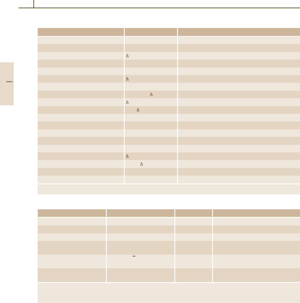
Table 1.2-13 Atomic units (a.u.)
Unit Symbol and definition Value in SI units
a.u. of charge: elementary charge e 1.60217653(14) ×10
−19
C
a.u. of mass: electron mass m
e
9.1093826(16) ×10
−31
kg
a.u. of action: reduced Planck constant = h/2π 1.05457168(18) ×10
−34
Js
a.u. of length, 1 bohr: Bohr radius a
0
= α/(4πR
∞
) 0.5291772108(18) ×10
−10
m
a.u. of energy, 1 hartree: Hartree energy
a
E
H
4.35974417(75) ×10
−18
J
a.u. of time /E
H
2.418884326505(16) ×10
−17
s
a.u. of force E
H
/a
0
8.2387225(14) ×10
−8
N
a.u. of velocity αc =a
0
E
H
/ 2.1876912633(73) ×10
6
m/s
a.u. of momentum /a
0
1.99285166(34) ×10
−24
kg m/s
a.u. of current eE
H
/ 6.62361782(57) ×10
−3
A
a.u. of charge density e/a
3
0
1.081202317(93) ×10
12
C/m
3
a.u. of electric potential E
H
/e 27.2113845(23) V
a.u. of electric field E
H
/(ea
0
) 5.14220642(44) ×10
11
V/m
a.u. of electric dipole moment ea
0
8.47835309(73) ×10
−30
Cm
a.u. of electric polarizability e
2
a
2
0
/E
H
1.648777274(16) ×10
−41
C
2
m
2
/J
a.u. of magnetic field B /(ea
2
0
) 2.35051742(20) ×10
5
T
a.u. of magnetic dipole moment (2µ
B
) 2µ
B
= e/m
e
1.85480190(16) ×10
−23
J/T
a.u. of magnetizability e
2
a
2
0
/m
e
7.89103660(13) ×10
−29
J/T
2
a.u. of permittivity e
2
/(a
0
E
H
) Fixed by definition as: 10
7
/c
2
= 1.112650056...10
−10
F/m
a
The Hartree energy is defined as E
H
= e
2
/(4πε
0
a
0
) = 2R
∞
hc =α
2
m
e
c
2
.
Table 1.2-14 Units of some special X-ray-related quantities
Unit Definition Symbol Value in SI units
Cu X unit λ(CuKα
1
)/1537.400 xu(CuKα
1
) 1.00207710(29) ×10
−13
m
Mo X unit λ(MoKα
1
)/707.831 xu(MoKα
1
) 1.00209966(53) ×10
−13
m
angstrom star λ(WKα
1
)/0.2090100 Å
∗
1.00001509(90) ×10
−10
m
Lattice parameter
a
of Si a 543.102122(20) ×10
−12
m
(in vacuum, at 22.5
◦
C)
(220) lattice spacing of Si d
220
= a/
√
8 d
220
192.0155965(70) ×10
−12
m
(in vacuum, at 22.5
◦
C)
Molar volume of Si V
m
(Si) = N
A
a
3
/8 V
m
(Si) 12.0588382(24) ×10
−6
m
3
/mol
(in vacuum, at 22.5
◦
C)
a
This is the lattice parameter (unit cell edge length) of an ideal single crystal of naturally occurring silicon free from impurities
and imperfections, and is deduced from measurements on extremely pure, nearly perfect single crystals of Si by correcting for the
effects of impurities.
Table 1.2-15 lists some other units which are com-
mon in older texts. For current texts, it should be noted
that if these units are used, the advantages of the SI are
lost. The relation of these units to SI units should be
specified in every document in which they are used.
For some selected quantities, there exists an inter-
national agreement that the numerical values of these
quantities measured in SI units are fixed at the values
given in Table 1.2-16.
Part 1 2.6

The International System of Units (SI), Physical Quantities, and Their Dimensions 2.6 Units Outside the SI 23
Table 1.2-15 Examples of other non-SI units
Unit Symbol Value in SI units
curie
a
Ci 1Ci= 3.7×10
10
Bq
röntgen
b
R 1R= 2.58 × 10
−4
C/kg
rad
c,d
rad 1rad= 1cGy= 10
−2
Gy
rem
d,e
rem 1rem= 1 cSv =10
−2
Sv
X unit
f
1 X unit
∼
=
1.002× 10
−4
nm
gamma
d
γ 1 γ = 1nT= 10
−9
T
jansky Jy 1Jy= 10
−26
W/(m
2
Hz)
fermi
d
1fermi= 1fm= 10
−15
m
metric carat
g
1 metric carat = 200 mg = 2×10
−4
kg
torr Torr 1Torr= (101 325/760) Pa
standard atmosphere atm
h
1atm= 101 325 Pa
calorie cal
i
micron
j
µ 1 µ = 1 µm =10
−6
m
a
The curie is a special unit employed in nuclear physics to express the activity of radionuclides.
b
The röntgen is a special unit employed to express exposure to X-ray or γ radiation.
c
The rad is a special unit employed to express absorbed dose of ionizing radiation. When there is a risk of confusion with the symbol
for the radian, rd may be used as the symbol for 10
−2
Gy.
e
The rem is a special unit used in radioprotection to express dose equivalent.
f
The X unit was employed to express wavelengths of X-rays. Its relationship to SI units is an approximate one.
d
Note that this non-SI unit is exactly equivalent to an SI unit with an appropriate submultiple prefix.
g
The metric carat was adopted by the 4th CGPM in 1907 for commercial dealings in diamonds, pearls, and precious stones.
h
Resolution 4 of the 10th CGPM, 1954. The designation “standard atmosphere” for a reference pressure of 101 325 Pa is still
acceptable.
i
Several “calories” have been in use:
•the 15
◦
C calorie: 1 cal
15
= 4.1855 J (value adopted by the CIPM in 1950);
•the IT (International Table) calorie: 1 cal
IT
= 4.1868 J (5th International Conference on the Properties of Steam, London, 1956);
•the thermochemical calorie: 1 cal
th
= 4.184 J.
j
The micron and its symbol, adopted by the CIPM in 1879 and repeated in Resolution 7 of the 9th CGPM (1948), were abolished by
the 13th CGPM (1967–1968).
Quantity Symbol Numerical value Unit
Relative atomic mass
a
of
12
C A
r
(
12
C) 12
Molar mass constant M
u
1×10
−3
kg/mol
Molar mass of
12
C M(
12
C) 12 × 10
−3
kg/mol
Conventional value K
J-90
483 597.9 GHz/V
of the Josephson constant
b
Conventional value R
K-90
25 812.807 Ω
of the von Klitzing constant
c
Standard atmosphere 101 325 Pa
Standard acceleration of free fall
d
g
n
9.80665 m/s
2
a
The relative atomic mass A
r
(X) of a particle X with mass m(X) is defined by A
r
(X) =
m(X)/m
u
, where m
u
= m(
12
C)/12 = M
u
/N
A
= 1 u is the atomic mass constant, M
u
is the
molar mass constant, N
A
is the Avogadro number, and u is the (unified) atomic mass unit. Thus
the mass of a particle X is m(X) = A
r
(X) u and the molar mass of X is M(X) = A
r
(X)M
u
.
b
This is the value adopted internationally for realizing representations of the volt using the
Josephson effect.
c
This is the value adopted internationally for realizing representations of the ohm using the
quantum Hall effect.
d
The value givenwasadopted by the3rd General Conferenceon Weights andMeasures (CGPM),
1903, and was the conventional value used to calculate the now obsolete unit kilogram force.
Table 1.2-16 Internationally
adopted numerical values for
selected quantities
Part 1 2.6
24 Part 1 General Tables
1.2.7 Some Energy Equivalents
In science and technology, energy is measured in
many different units. Different units are used de-
pending on the field of application, but owing to
the different possible forms of the energy con-
cerned, it is possible also to express the energy in
terms of other quantities. All forms of the energy,
however, are quantitatively related to one another
and are therefore considered as being equivalent.
Some of the most important equivalence relations
are
E = eU = mc
2
= hc/λ = hν =kT .
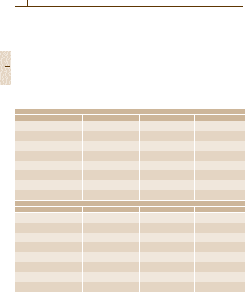
Table 1.2-17 Energy equivalents, expressed in the units joule (J), hartree (E
H
), volt (V), kilogram (kg), (unified) atomic mass unit
(u), reciprocal meter (m
−1
), hertz (Hz), and kelvin (K)
Unit
Energy Joule Hartree Volt Kilogram
1J (1J) = 1J (1J)
= 2.29371257(39) ×10
17
E
H
(1J)
= 6.24150947(53) ×10
18
eV
(1J)/c
2
= 1.112650056 × 10
−17
kg
1 E
H
(1 E
H
)
= 4.35974417(75) ×10
−18
J
(1 E
H
) = 1 E
H
(1 E
H
)
= 27.2113845(23) eV
(1 E
H
)/c
2
= 4.85086960(83) ×10
−35
kg
1eV (1eV)
= 1.60217653(14) ×10
−19
J
(1eV)
= 3.67493245(31) ×10
−2
E
H
(1eV) = 1eV (1eV)/c
2
= 1.78266181(15) ×10
−36
kg
1kg (1kg) c
2
= 8.987551787 × 10
16
J
(1kg) c
2
= 2.06148605(35) ×10
34
E
H
(1kg) c
2
= 5.60958896(48) ×10
35
eV
(1kg) = 1kg
1u (1u) c
2
= 1.49241790(26) ×10
−10
J
(1u) c
2
= 3.423177686(23) ×10
7
E
H
(1u) c
2
= 931.494043(80) ×10
6
eV
(1u)
= 1.66053886(28) ×10
−27
kg
1m
−1
(1m
−1
) hc
= 1.98644561(34) ×10
−25
J
(1m
−1
) hc
= 4.556335252760(30) ×10
−8
E
H
(1m
−1
) hc
= 1.23984191(11) ×10
−6
eV
(1m
−1
) h/c
= 2.21021881(38) ×10
−42
kg
1Hz (1Hz) h
= 6.6260693(11) ×10
−34
J
(1Hz) h
= 1.519829846006(10) ×10
−16
E
H
(1Hz) h
= 4.13566743(35) ×10
−15
eV
(1Hz) h/c
2
= 7.3724964(13) ×10
−51
kg
1K (1K) k
= 1.3806505(24) ×10
−23
J
(1K) k
= 3.1668153(55) ×10
−6
E
H
(1K) k
= 8.617343(15) ×10
−5
eV
(1K) k/c
2
= 1.5361808(27) ×10
−40
kg
Unit
Energy Atomic mass unit Reciprocal meter Hertz Kelvin
1J (1J)/c
2
= 6.7005361(11) ×10
9
u
(1J)/hc
= 5.03411720(86) ×10
24
m
−1
(1J)/h
= 1.50919037(26) ×10
33
Hz
(1J)/k
= 7.242963(13) ×10
22
K
1 E
H
(1 E
H
)/c
2
= 2.921262323(19) ×10
−8
u
(1 E
H
)/hc
= 2.194746313705(15) ×10
7
m
−1
(1 E
H
)/h
= 6.579683920721(44) ×10
15
Hz
(1 E
H
)/k
= 3.1577465(55) ×10
5
K
1eV (1eV)/c
2
= 1.073544171(92) ×10
−9
u
(1eV)/hc
= 8.06554445(69) ×10
5
m
−1
(1eV)/h
= 2.41798940(21) ×10
14
Hz
(1eV)/k
= 1.1604505(20) ×10
4
K
1kg (1kg)
= 6.0221415(10) ×10
26
u
(1kg) c/h
= 4.52443891(77) ×10
41
m
−1
(1kg) c
2
/h
= 1.35639266(23) ×10
50
Hz
(1kg) c
2
/k
= 6.509650(11) ×10
39
K
1u (1u) = 1u (1u) c/h
= 7.513006608(50) ×10
14
m
−1
(1u) c
2
/h
= 2.252342718(15) ×10
23
Hz
(1u) c
2
/k
= 1.0809527(19) ×10
13
K
1m
−1
(1m
−1
) h/c
= 1.3310250506(89) ×10
−15
u
(1m
−1
) = 1m
−1
(1m
−1
) c
= 299 792 458 Hz
(1m
−1
) hc/k
= 1.4387752(25) ×10
−2
K
1Hz (1Hz) h/c
2
= 4.439821667(30) ×10
−24
u
(1Hz)/c
= 3.335640951 × 10
−9
m
−1
(1Hz) = 1Hz (1Hz) h/k
= 4.7992374(84) ×10
−11
K
1K (1K) k/c
2
= 9.251098(16) ×10
−14
u
(1K) k/hc
= 69.50356(12) m
−1
(1K) k/h
= 2.0836644(36) ×10
10
Hz
(1K) = 1K
These equations tell us that a given energy E,whichis
usually measured either in units of joule (J) or units of
the Hartree energy (E
H
= 1 hartree), can also be speci-
fied by giving a voltage U,amassm, a wavelength λ,
a frequency ν, or a temperature T. These equations con-
tain, in addition to those variables, only well-known
fundamental constants.
Table 1.2-17 gives the values of the energy equiva-
lents of the joule and the hartree and for the SI units
corresponding to the five quantities U, m,λ,ν,andT .
The equivalents have been calculated on the basis of the
2002 CODATA adjustment of thevalues of the constants.
Part 1 2.7

The International System of Units (SI), Physical Quantities, and Their Dimensions References 25
References
2.1 Bureau International des Poids et Mesures: Le
système international d’unités, 7th edn. (Bu-
reau International des Poids et Mesures,
1998)
2.2 Organisation Intergouvernementale de la Conven-
tion du The International System of Units (SI),
Addenda and Corrigenda to the 7th Edition (Bureau
International des Poids et Mesures,
2000)
Part 1 2
Sèvres
Sèvres
Mètre:

26
This page intentionally left blank

27
Rudiments of
1.3. Rudiments of Crystallography
Crystallography deals basically with the question
“Where are the atoms in solids?” The purpose
of this section is to introduce briefly the ba-
sics of modern crystallography. The focus is on
the description of periodic solids, which repre-
sent the major proportion of condensed matter.
A coherent introduction to the formalism re-
quired to do this is given, and the basic concepts
and technical terms are briefly explained. Pay-
ing attention to recent developments in materials
research, we treat aperiodic, disordered, and
amorphous materials as well. Consequently,
besides the conventional three-dimensional
(3-D) descriptions, the higher-dimensional
crystallographic approach is outlined, and so is the
atomic pair distribution function used to describe
1.3.1 Crystalline Materials ........................... 28
1.3.1.1 Periodic Materials ................... 28
1.3.1.2 Aperiodic Materials.................. 33
1.3.2 Disorder............................................. 38
1.3.3 Amorphous Materials .......................... 39
1.3.4 Methods for Investigating
Crystallographic Structure.................... 39
References .................................................. 41
local phenomena. The section is concluded by
touching on the basics of diffraction methods, the
most powerful tool kit used by experimentalists
dealing with structure at the atomic level in the
solid state.
The structure of a solid material is very important,
because the physical properties are closely related to
the structure. In most cases solids are crystalline: they
may consist of one single crystal, or be polycrystalline,
consisting of many tiny single crystals in different orien-
tations. All periodic crystals have a perfect translational
symmetry. This leads to selection rules, which are very
useful for the understanding of the physical proper-
ties of solids. Therefore, most textbooks on solid-state
physics begin with some chapters on symmetry and
structure. Today we know that other solids, which have
no translational symmetry, also exist. These are amor-
phous materials, which have little order (in most cases
restricted to the short-range arrangement of the atoms),
and aperiodic crystals, which show perfect long-range
order, but no periodicity – at least in 3-D space. In this
chapter of the book, the basic concepts of crystallogra-
phy – how the space of a solid can be filled with atoms –
are briefly discussed. Readers who want to inform them-
selves in more detail about crystallography are referred
to the classic textbooks [3.1–5].
Many crystalline materials, especially minerals and
gems, were described more than 2000 years ago. The
regular form of crystals and the existence of facets,
which have fixed angles between them, gave rise to
a belief that crystals were formed by a regular repetition
of tiny, identical building blocks. After the discovery
of X-rays by Röntgen, Laue investigated crystals in
1912 using these X-rays and detected interference ef-
fects caused by the periodic array of atoms. One year
later, Bragg determined the crystal structures of alkali
halides by X-ray diffraction.
Today we know that a crystal is a 3-D array of atoms
or molecules, with various types of long-range order.
A more modern definition is that all materials which
show sharp diffraction peaks are crystalline. In this
sense, aperiodic or quasicrystalline materials, as well
as periodic materials, are crystals. A real crystal is never
a perfect arrangement. Defects in the form of vacancies,
dislocations, impurities, and other imperfections are of-
ten veryimportant for the physicalproperties of a crystal.
This aspect has been largely neglected in classical crys-
tallography but is becoming more and more a topic of
modern crystallographic investigations [3.6,7].
As indicated in Table 1.3-1, condensed matter can
be classified as either crystalline or amorphous. Both
of these states and their formal subdivisions will be
discussed in the following. The terms “matter”, “struc-
ture”, and “material” always refer to single-phase
solids.
Part 1 3
28 Part 1 General Tables
Table 1.3-1 Classification of solids
Condensed matter (solids)
Crystalline materials
Amorphous materials
Periodic structures
Aperiodic structures
Modulated structures Composite structures Quasicrystals
1.3.1 Crystalline Materials
1.3.1.1 Periodic Materials
Lattice Concept
A periodic crystal is described by two entities, the lattice
and the basis. The (translational) lattice is a perfect geo-
metrical array of points. All lattice points are equivalent
and have identical surroundings. This lattice is defined
by three fundamental translation vectors a, b, c. Starting
from an arbitrarily chosen origin of the lattice, any other
lattice point can be reached by a translation vector r that
satisfies
r = ua +vb +wc ,
where u, v,andw are arbitrary integers.
The lattice is an abstract mathematical construction;
the description of the crystal is completed by attaching
a set of atoms –the basis – to each lattice point. Therefore
the crystal structure is formed by a lattice and a basis
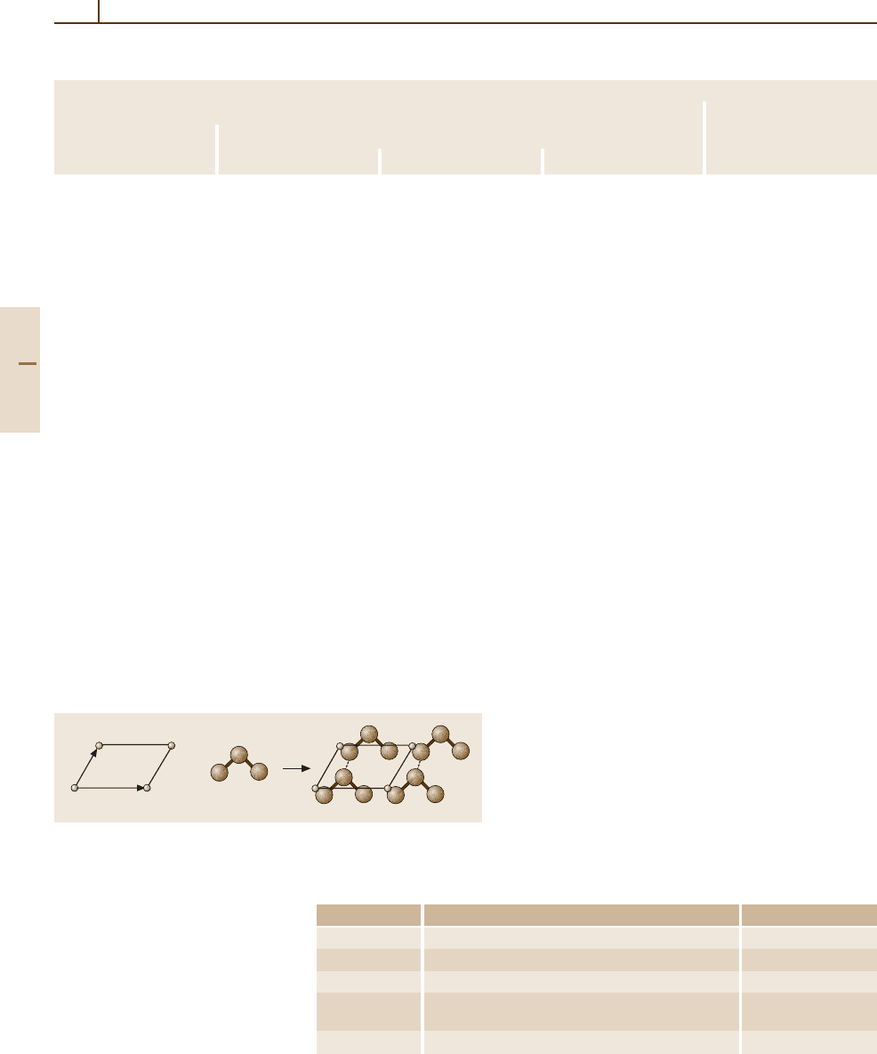
(see Fig. 1.3-1).
The parallelepiped that is defined by the axes a, b, c
is called a primitive cell if this cell has the small-
b
a
×
Fig. 1.3-1 A periodic crystal can be described as a convolution of
a mathematical point lattice with a basis (set of atoms). Open circles,
mathematical points; filled circles, atoms
Symbol Description Points per unit cell
P No centering (primitive) 1
I Body-centered (innenzentriert) 2
F All-face-centered 4
S; A, B, C One-face-centered (seitenzentriert); 2
in specific cases
(b, c), (a, c), and (a, b), respectively, in specific cases
R Hexagonal cell, rhombohedrally centered 3
Table 1.3-2 Centering types
for 3-D crystallographic unit
cells
est volume out of all possible cells. It contains one
lattice point per cell only (Fig. 1.3-2a). This cell is
a type of unit cell which fills the space of the crys-
tal completely under the application of the translation
operations of the lattice, i. e. movements along the
vectors r.
Conventionally, the smallest cell with the highest
symmetry is chosen. Crystal lattices can be transformed
into themselves by translation along the fundamental
vectors a, b, c, but also by other symmetry opera-
tions. It can be shown that only onefold (rotation angle
ϕ = 2π/1), twofold (2π/2), threefold (2π/3), fourfold
(2π/4), and sixfold (2π/6) rotation axes are permissible.
Other rotational axes cannot exist in a lattice, because
they would violate the translational symmetry. For ex-
ample, it is not possible to fill the space completely
with a fivefold (2π/5) array of regular pentagons. Ad-
ditionally, mirror planes and centers of inversion may
exist. The restriction to high-symmetry cells may also
lead to what is known as centering. Figure 1.3-2b illus-
trates a 2-D case. The centering types in 3-D are listed
in Table 1.3-2.
Planes and Directions in Lattices
If one peers through a 3-D lattice from various angles, an
infinity of equidistant planes can be seen. The position
and orientation of such a crystal plane are determined
by three points. It is easy to describe a plane if all
three points lie on crystal axes (i. e. the directions of
unit cell vectors); in this case only the intercepts need
to be used. It is common to use Miller indices to de-
Part 1 3.1
Rudiments of Crystallography 3.1 Crystalline Materials 29
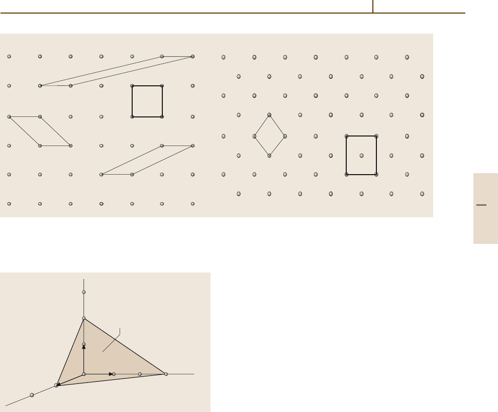
a) b)
Fig. 1.3-2a,b Possible primitive and centered cells in 2-D lattices. Open circles denote mathematical points. (a) In this
lattice, the conventional cell is the bold square cell because of its highest symmetry, 4mm.
(b) Here, convention prefers
90
◦
angles: a centered cell of symmetry 2mm is chosen. It contains two lattice points and is twice the area of the primitive
cell
z
2
x
y
(623)
1
3
a
c
b
Fig. 1.3-3 Miller indices: the intercepts of the (623) plane
with the coordinate axes
scribe lattice planes. These indices are determined as
follows:
1. For the plane of interest, determine the intercepts
x, y, z of the crystal axes a, b, c.
2. Express the intercepts in terms of the basic vectors
a, b, c of the unit cell, i. e. as x/a, y/b, z/c (where
a =|a|,...).
3. Form the reciprocals a/x, b/y, c/z.
4. Reduce this set to the smallest integers h, k, l. The
result is written (hkl).
The distance from the origin to the plane (hkl)in-
side the unit cell is the interplanar spacing d
hkl
.Negative
intercepts, leading to negative Miller indices, are writ-
ten as
¯
h. Figure 1.3-3 shows a (623) plane and its
construction.
A direction in a crystal is given as a set of three
integers in square brackets [uvw]; u, v, and w corres-
pond to the above definition of the translation vector r.
A direction in a cubic crystal can be described also by
Miller indices, as a plane can be defined by its nor-
mal. The indices of a direction are expressed as the
smallest integers which have the same ratio as the com-
ponents of a vector (expressed in terms of the axis
vectors a, b, c) in that direction. Thus the sets of in-
tegers 1, 1, 1and3, 3, 3 represent the same direction
in a crystal, but the indices of the direction are [111]
and not [333]. To give another example, the x axis of
an orthogonal x, y, z coordinate system has Miller in-
dices [100]; the plane perpendicular to this direction has
indices (100).
For all crystals, except for the hexagonal system,
the Miller indices are given in a three-digit system in the
form (hkl). However, for the hexagonalsystem, it is com-
mon to use four digits (hkil). The four-digit hexagonal
indices are based on a coordinate system containing four
axes. Three axes lie in the basal plane of the hexagon,
crossing at angles of 120
◦
: a , b,and−(a +b).Asthe
third vector in the basal plane can be expressed in terms
of a and b, the index can be expressed in terms of h and k:
i =−(h +k). The fourth axis is the c axis normal to the
basal plane.
Part 1 3.1
30 Part 1 General Tables
Crystal Morphology
The regular facets of a crystal are planes of the
type described above. Here, the lattice architecture of
the crystal is visible macroscopically at the surface.
Figure 1.3-4 shows some surfaces of a cubic crys-
tal. If the crystal had the shape or morphology of
a cube, this would be described by the set of facets
{(100), (010), (001), (
¯
100), (0
¯
10), (00
¯
1)}. An octahe-
dron would be described by {(111), (
¯
111), (1
¯
11), (11
¯
1),
(
¯
1
¯
1
¯
1), (1
¯
1
¯
1), (
¯
11
¯
1), (
¯
1
¯
11)}. The morphology of a crys-
talline material may be of technological interest (in
relation to the bulk density, flow properties, etc.) and can
be influenced in various ways, for example by additives
during the crystallization process.
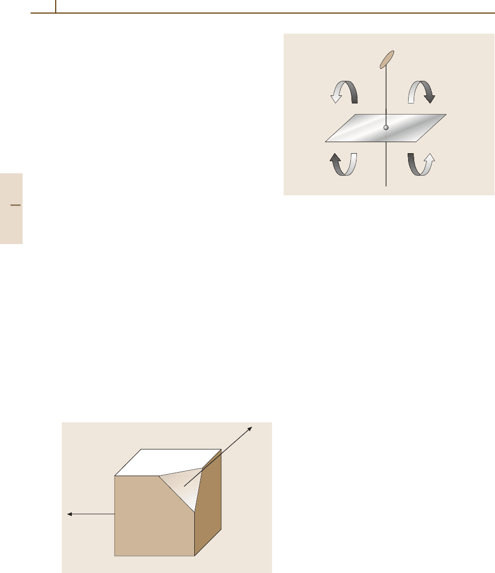
The 32 Crystallographic Point Groups
The symmetry of the space surrounding a lattice point
can be described by the point group, which is a set of
symmetry elements acting on the lattice. The crystal-
lographic symbols for the symmetry elements of point
groups compatible with a translational lattice are the ro-
tation axes 1, 2, 3, 4, and 6, mirror planes m,andthe
center of inversion
¯
1. Figure 1.3-5 illustrates, as an ex-
ample, the point group 2/m. The “2” denotes a twofold
axis perpendicular (“/”) to a mirror plane “m”. Note
that this combination of 2 and m implies, or gener-
ates automatically, an inversion center
¯
1. We have used
the Hermann–Mauguin notation here; however, point
groups of isolated molecules are more often denoted
by the Schoenflies symbols. For a translation list, see
Table 1.3-3.
No crystal can have a higher point group symmetry
than the point group of its lattice, called the holohedry.
In accordance with the various rotational symmetries,
(100)
(001)
(010)
[111]
[00-1]
(111)
Fig. 1.3-4 Some crystal planes and directions in a cubic
crystal, and their Miller indices
2
m
–1
Fig. 1.3-5 The point group 2/m (C
2h
). Any object in space
can be rotated by ϕ =2π/2 around the twofold rotational
axis 2 and reflected by the perpendicular mirror plane m,
generating identical copies. The inversion center
¯
1 is im-
plied by the coupling of 2 and m
there are seven crystal systems (see Table 1.3-3), and
the seven holohedries are
¯
1, 2/m, mmm,4/mmm,
¯
3m,
6/mmm,andm
¯
3m. Other, less symmetric, point groups
are also compatible with these lattices, leading to a to-
tal number of 32 crystallographic point groups (see
Table 1.3-4). A lower symmetry than the holohedry
can be introduced by a less symmetric basis in the unit
cell.
Since
¯
3m and 6/mmm are included in the same point
lattice, they are sometimes subsumed into the hexagonal
crystal family. So there are seven crystal systems but six
crystal families. Note further that rhombohedral sym-
metry is a special case of centering (R-centering) of the
trigonal crystal system and offers two equivalent possi-
bilities for selecting the cell parameters: hexagonal or
rhombohedral axes (see Table 1.3-4 again).
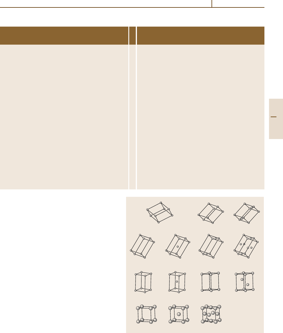
It can be shown that in 3-D there are 14 different
periodic ways of arranging identical points. These 14
3-D periodic point lattices are called the (translational)
Bravais lattices and are shown in Fig. 1.3-6. Table 1.3-4
presents data related to some of the crystallographic
terms used here. The 1-D and 2-D space groups can be
classified analogously but are omitted here.
The 230 Crystallographic Space Groups
Owing to the 3-D translational periodicity, symmetry
operations other than point group operations are pos-
sible in addition: these are glide planes and screw
axes. A glide plane couples a mirror operation and
a translational shift. The symbols for glide planes
Part 1 3.1
Rudiments of Crystallography 3.1 Crystalline Materials 31
Table 1.3-3 The 32 crystallographic point groups: translation list from the Hermann–Mauguin to the Schoenflies notation
Crystal Hermann–Mauguin Schoenflies Crystal Hermann–Mauguin Schoenflies
system symbol symbol
system symbol symbol
Triclinic 1 C
1
Trigonal 3 C
3
¯
1 C
i
¯
3 C
3i
Monoclinic 2 C
2
32 D
3
mC
s
3mC
3v
2/mC
2h
¯
3mD
3d
Orthorhombic 222 D
2
Hexagonal 6 C
6
mm2 C
2v
¯
6 C
3h
mmm D
2h
6/mC
6h
Tetragonal 4 C
4
622 D
6
¯
4 S
4
6mm C
6v
4/mC
4h
¯
62mD
3h
422 D
4
6/mmm D
6h
4mm C
4v
Cubic 23 T
¯
42mD
2d
m
¯
3 T
h
4/mmm D
4h
432 O
¯
43mT
d
m
¯
3mO
h
are a, b,andc for translations along the lattice vec-
tors a, b,andc, respectively, and n and d for some
special lattice vector combinations. A screw axis is
always parallel to a rotational axis. The symbols are
2
1
, 3
1
, 3
2
, 4
1
, 4
2
, 4
3
, 6
1
, 6
2
, 6
3
, 6
4
, and 6
5
, where, for
example, 6
3
means a rotation through an angle ϕ =2π/6
followed by a translation of 3/6 (= 1/2) of a full trans-
lational period along the sixfold axis.
Thus the combination of 3-D translational and point
symmetry operations leads to an infinite number of sets
of symmetry operations. Mathematically, each of these
sets forms a group, and they are called space groups.
It can be shown that all possible periodic crystals can
be described by only 230 space groups. These 230
space groups are described in tables, for example the
International Tables for Crystallography [3.8].
In this formalism, a conventional space group sym-
bol reflects the symmetry elements, arranged in the order
of standardized blickrichtungen (symmetry directions).
We shall confine ourselves here toexplain one instructive
example: P4
2
/mcm, space group number 132 [3.8]. The
full space group symbol is P 4
2
/m 2/c 2/m. The mean-
aP mP mC
oP oI oC oF
tP tI
hP
hR
cP cI cF
Fig. 1.3-6 The 14 Bravais lattices
Part 1 3.1