Mahle GmbH (Ed.) Cylinder Components: Properties, applications, materials
Подождите немного. Документ загружается.


1.6 Materials, coatings, and surface treatment 21
MF 025
Martensitic alloyed gray cast iron
High wear resistance
Alloying elements: Mo, Nb, V, W
ISO 6621-3: Subclass 25
High ultimate tensile strength with good wear resistance for second compression rings in
gasoline and diesel engines
Bending strength: min. 650 MPa
Hardness: 37 to 45 HRC
MF 032
Martensitic carbidic gray cast iron
High wear resistance
Alloying elements: Mo, Nb, V, W
ISO 6621-3: Subclass 32
High ultimate tensile strength with good wear resistance for second compression rings in
gasoline and diesel engines
Bending strength: min. 650 MPa
Hardness: 35 to 45 HRC
1.6.2.2 Martensitic nodular cast iron as a base material
MF 053
Martensitic nodular cast iron
Alloying elements: Ni, Mo
I
SO 6621-3: Subclass 53
First piston ring with high ultimate tensile strength and two-piece low-profile oil control rings
in gasoline and diesel engines
Bending strength: min. 1,300 MPa
Hardness: 28 to 42 HRC
MF 056
Martensitic carbidic nodular cast iron
Alloying elements: Ni, Mo, Nb
ISO 6621-3: Subclass 56
First piston ring with high ultimate tensile strength and two-piece low-profile oil control rings
in gasoline and diesel engines
Bending strength: min. 1,300 MPa
Hardness: 35 to 45 HRC

22 1 Piston rings
1.6.2.3 Carbon and stainless steels
MS 068
Carbon steel
Martensitic heat-treated
ISO 6621-3: Subclass 68
Base material for chrome-plated rails in three-piece oil control rings in gasoline engines
Tensile strength: no fracture in bending test
Hardness: 68 to 72 HR30N
MS 067
Austenitic stainless steel
Alloying elements: Cr, Ni
ISO 6621-3: Subclass 67
Expander ES-1 (type 81) for three-piece oil control rings in gasoline engines
Tensile strength: no fracture in bending test
Hardness: 59 to 67 HR30N
MS 062
Steel alloyed with chromium and silicon
ISO 6621-3: Subclass 62
Heat-resistant springs in two-piece oil control rings in diesel and gasoline engines
Tensile strength: 1,800 to 2,000 MPa
MS 066
Martensitic stainless steel
Alloying elements: Cr, Mo
ISO 6621-3: Subclass 66
Base material for nitrided, chrome-plated, or molybdenum-coated first piston rings in diesel
and gasoline engines
Tensile strength: 1,125 to 1,325 MPa
Hardness: 38 to 42 HRC
MS 064
Steel alloyed with chromium and silicon
ISO 6621-3: Subclass 64
Base material for chrome-plated, molybdenum-coated, and high-speed flame-sprayed first
piston rings for diesel and gasoline engines
Tensile strength: 1,590 to 1,960 MPa
Hardness: 48 to 54 HRC

1.6 Materials, coatings, and surface treatment 23
1.6.2.4 Running face and side face coatings
MCR 005
Chrome plating of the side faces
Galvanically applied
Coating of the side faces for first piston rings
High wear resistance on the bottom side and resistance to plating build-up
Hardness: min. 800 HV
MCR 024
Hard chrome plating
Galvanically applied
Piston rings in gasoline or diesel engines
Good wear resistance and seizure resistance
Hardness: min. 800 HV 0.1
MCR 236
Chrome-ceramic
Galvanically applied
Piston rings in diesel engines
Excellent wear and seizure resistance
Hardness: 900 to 1,200 HV 0.1
MSC 125/MSC 251/MSC 278/MSC 280
Mo + NiCr alloy (MSC 251, MSC 278) + Cermet (MSC 125, MSC 280)
Plasma-sprayed coating
Piston rings in gasoline or diesel engines
Good wear resistance and high seizure resistance
Hardness: min. 300 HV (MSC 125), min. 325 (MSC 251), min. 450 HV (MSC 278 and
MSC 280)
MSC 380
HVOF-Cermet
Coating by high-speed flame spraying
For first piston rings in diesel engines
Superior wear resistance and seizure resistance
Hardness: min. 500 HV

24 1 Piston rings
MSC 480
HDP-Cermet
Coating by optimized plasma-spray process (high-density plasma)
For first piston rings in diesel engines
Excellent wear resistance and seizure resistance
Hardness: min. 450 HV
MIP 230/MIP 250
Chrome-nitride coating with cathode-ray sputtering (PVD) – MIP 230
Doped chrome-nitride coating with cathode-ray sputtering (PVD) – MIP 250
For first piston rings in diesel engine and I-shaped oil control rings
Superior wear resistance and seizure resistance
Hardness: 1,200 to 1,600 HV (MIP 230); 1,600 to 2,000 HV (MIP 250)
1.6.2.5 Nitriding of running faces
MF 024 – N
Nitrided martensitic gray cast iron
S
econd rings in gasoline and diesel engines
Excellent wear resistance
ISO 6621-3: Subclass 24
Hardness: min. 600 HV 0.025 at 0.01 mm, min. 500 HV 0.050 at 0.03 mm
MS 065 – N
Nitrided 10 or 13% chromium stainless steel
Rails in three-piece oil control rings
High wear resistance
ISO 6621-3: Subclass 65
Hardness: min. 900 HV 0.050 at 0.01 mm, min. 700 HV 0.1 at 0.03 mm
MS 066 – N
Nitrided 17% Cr martensitic stainless steel
First piston ring in diesel engines, oil control rings in diesel and gasoline engines
High wear resistance
ISO 6621-3: Subclass 66
Hardness: min. 900 HV 0.050 at 0.01 mm, min. 700 HV 0.1 at 0.03 mm

1.6 Materials, coatings, and surface treatment 25
MS 067 – N
Nitrided austenitic stainless steel
Expander ES-2 (type 81) in gasoline engines
Excellent heat resistance and low tangential force loss
ISO 6621-3: Subclass 67
Nitrided area: min 0.004 mm
1.6.2.6 Surface protection
Some surface treatments can be used for special purposes, such as for oxidation resistance
or for protection against microwelding (Table 1
.1).
Table 1.1: Properties and applications of various protective coatings
MCA standard Protective coating or
treatment
Groove Properties
MPR 001 Tin-plating First piston ring Oxidation resistance
Run-in compatibility
MPR 022 Black-oxidizing Oil control rings and
rails
Oxidation resistance
MPR 023 Manganese phosphate First piston rings and
oil control rings
Oxidation resistance
MPR 152 Polymer coating First piston ring Resistance to microwelding
MPR 207 Zinc phosphate First piston rings and
oil control rings
Oxidation resistance
27
2 Piston pins and piston pin circlips
2.1 Function of the piston pin
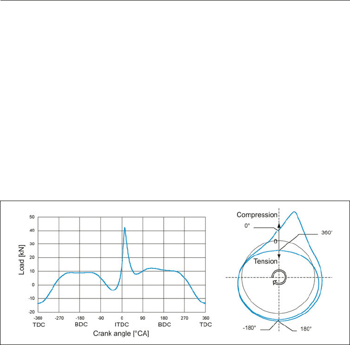
The piston pin is the link between the piston and the connecting rod. Due to the oscillating
motion of the piston and the interaction of gas and inertial forces, it is subjected to high loads
in alternating directions. Figure 2.1 shows the piston pin load for a gasoline engine at rated
power. The rotary motion of the connecting rod relative to the piston must be compensated
for at the bearing locations of the piston pin, in the pin boss, and the small end bore. Due to
the small relative motions, the lubrication conditions here are poor.
Figure 2.1: Piston pin load
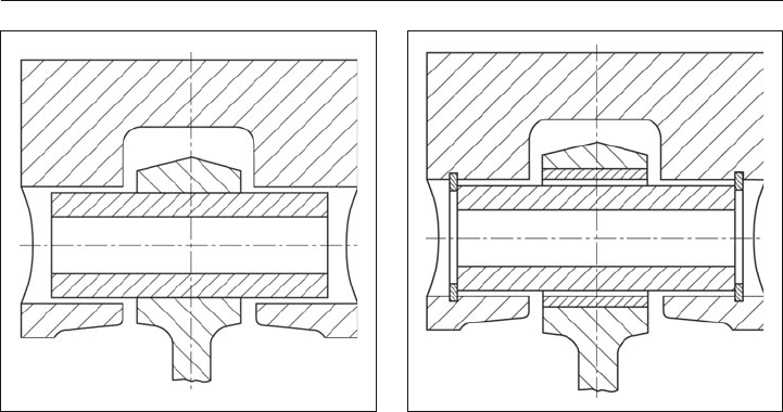
For pistons in gasoline engines of passenger cars with moderate specific output, the piston
pins can be fixed in the small end bore with shrinkage stresses (fixed pin connecting rod)
(Figure 2.2). This design allows savings due to the elimination of the piston pin circlips and
the bushing in the small end bore and makes automatic assembly of the piston, piston pin,
and connecting rod easier for high-volume production of engines.
In highly stressed gasoline engines and in diesel engines, the piston pin “floats” in the small
end bore (Figure 2.3). It needs to be secured with piston pin circlips to eliminate sideways
movement in the piston pin (see Section 2.7).
In large-bore pistons, the cooling oil is often fed through the connecting rod and the piston
pin, which features special oil feeding systems, to the pin boss.
28 2 Piston pins and piston pin circlips
2.2 Requirements
2.2.1 General
Piston pins must meet the following requirements:
N sufficient strength and ductility to withstand the loads without damage,
N high surface hardness, in order to achieve favorable wear behavior,
N high surface quality and shape accuracy for optimal fit with its sliding counterparts, the
piston and connecting rod,
N low weight, in order to keep inertia forces minimal,
N stiffness must be matched to the piston design, in order to avoid overloading the piston.
Despite these sometimes contradictory requirements, piston pin manufacture must be as
simple, and thus economical, as possible.
2.2.2 Strength
Under the effects of the gas and inertia forces, pressure and stress loads act on the piston
pin surface, the distribution of which is determined by the deformations of the piston pin
bores, piston pins, and small end bore, caused by the forces (see Section 2.4.3). As a result
of this pressure distribution, the piston pin is subjected to bending, ovalization, and shear
force. Added to this is a torsional load due to the connecting rod tilting motion. It is neglected
because of its limited proportion in the total load. On the other hand, the requirement is that
the piston pin must be as stiff and as light as possible.
Figure 2.2: Fixed pin connecting rod Figure 2.3: Connecting rod with floating pin
2.2 Requirements 29
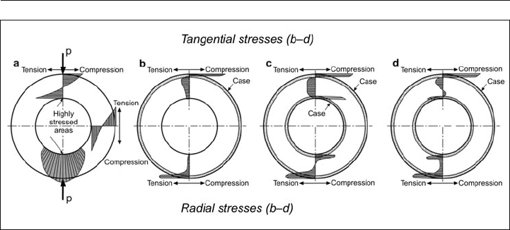
Figure 2.4: Stress distribution on the piston pin
a) effect of ovalization
b) without case hardening at inner bore
c) with case hardening at inner bore
d) decarburization at inner bore
Figure 2.4 shows the stress distribution on the piston pin during ovalization and various
microstructure states at the surface.
The ovalization of the piston pin results in the stress distribution shown in Figure 2.4a. The
maximum tensile stresses critical for fatigue resistance are inside, on the surface of the bore.
Residual stresses applied at the inner bore can counteract these tensile stresses, which has
a positive effect on the fatigue resistance of the piston pin. The same applies analogously for
the outside diameter, which is loaded mainly through bending.
The carbon and nitrogen diffusion into the surface layer, associated with case hardening or
nitriding of the piston pin, results in an increase in volume and thus residual stresses in the
layer. The effect on the residual stress state of the piston pin is shown in Figures 2.4b-d.
Practical experience confirms that this significantly increases fatigue resistance.
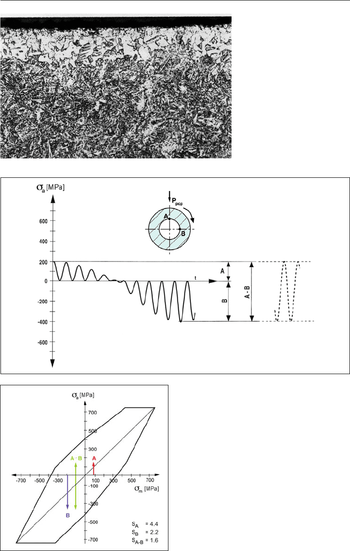
Decarburization of the bore surface (Figure 2.5), which leads to residual tensile stresses
(Figure 2.4d), is extremely detrimental to the fatigue resistance of the piston pin. Hardening
cracks, slag lines, and deep machining lines in the bore also greatly reduce fatigue resis-
tance.
Floating piston pins can rotate. This means that highly loaded positions of the piston pin
can move into less highly loaded positions, or from tensile to compressive loads, and vice
versa. This results in a varying load on the piston pin. These stress amplitudes result in higher
loading of the component, in contrast to piston pins that are fixed in the connecting rod,
and therefore do not rotate. Figure 2.6 shows the differences between a fixed and a rotating
piston pin, using stress amplitudes.
30 2 Piston pins and piston pin circlips
Figure 2.5:
Decarburization of the bore
surface of the piston pin
Figure 2.6:
Stress in a piston pin fixed in a connecting rod
(A, B) and a rotating piston pin (A-B)
2.2 Requirements 31
The pin loads are evaluated using a fatigue strength map, e.g., according to Smith. Such a
fatigue strength map must be determined for each material in use. Its limit lines correspond
to the safety factor S = 1. The permissible minimum safety factor is determined according to
the requirements and expected loads for each area of application, such as passenger cars,
commercial vehicles, or motorsport.
Clearance between the piston pin and the pin boss or connecting rod small end should be
selected such that scuffing cannot occur between the contact areas with the piston and the
connecting rod. The clearance should be checked carefully, especially under warm operating
conditions, due to different thermal expansion coefficients of the materials used.
In order to avoid pin boss cracks, limits of the temperature-dependent material and load fac-
tors, such as surface pressure in the boss, must not be exceeded.
2.2.3 Deformation
Another requirement is that the piston pin must be light, in addition to having sufficient rigid-
ity and strength. Rigidity relative to bending can be increased greatly, as the fourth power
of the increase in diameter. Bending also increases approximately as the third power of the
support span of the piston pin, i.e., with the pin boss spacing. A reduction in this value thus
causes a significant reduction in bending and thus increases rigidity. If a shorter piston pin
can be used, then mass reduction is also possible.
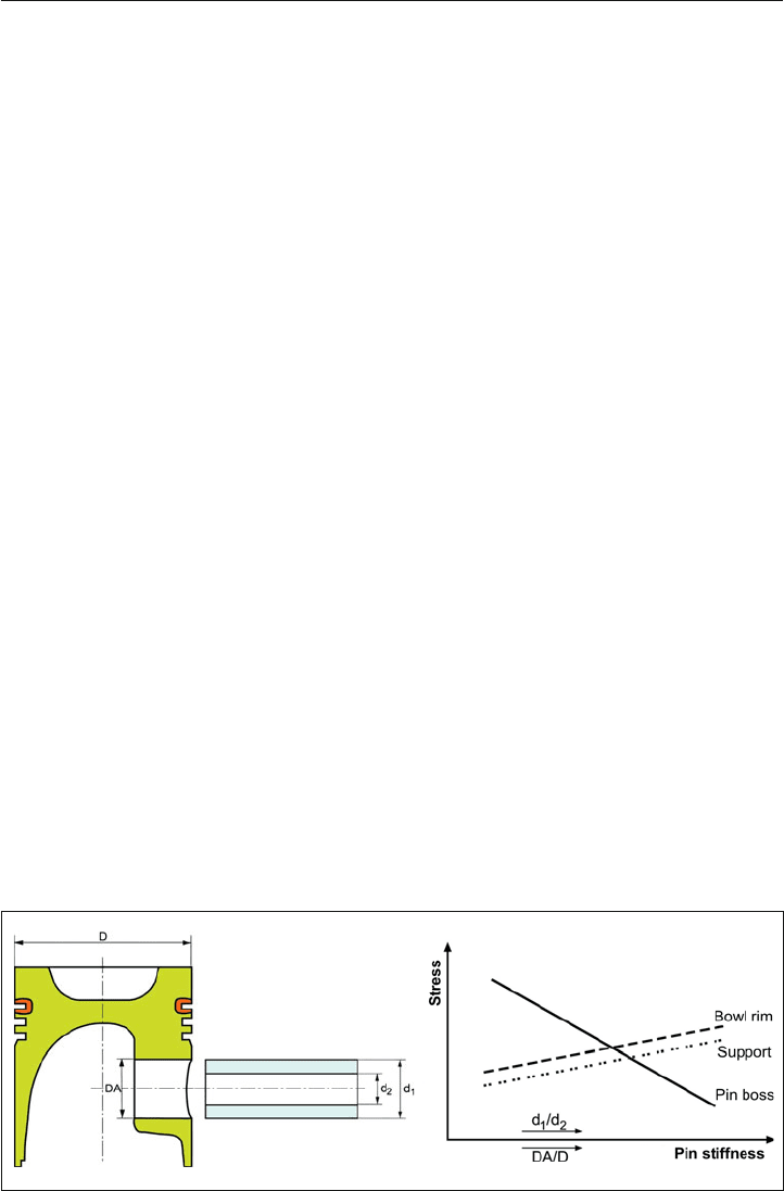
An increase in rigidity relative to ovalization can be achieved only with a greater wall thick-
ness and thus always increases mass. The stiffness of the piston pin has a significant effect
on the loads on the pin bore, pin boss, support, and bowl rim, as shown in Figure 2.7.
The susceptibility of the piston to pin boss cracks is shown in Figure 2.8 as a function of
the piston pin geometry, as a result of engine testing. Due to higher peak cylinder pres-
Figure 2.7: Piston stress as a function of piston pin stiffness