Lyons W.C. (ed.). Standard handbook of petroleum and natural gas engineering.2001- Volume 1
Подождите немного. Документ загружается.

MWD and LWD
925
where m is the decelerated mass. For a 2-kg mass and am
=
500 g
(5,000
m/s*)
F
=
2
x
0.66
x
5000
=
660
daN
Note:
1
daN
=
2.25
Ib
Measuring devices run inside the drillstring are mainly subject to axial
impacts. These shocks come from sudden halts in the mule shoe or from an
obstruction in the string. The measuring devices used while drilling are generally
subjected to axial and angular impacts caused by the bouncing of the bit on
the bottom and by the catching of the rollers and stabilizers on the borehole
walls. There is very little information in the literature about measuring impacts
while drilling.
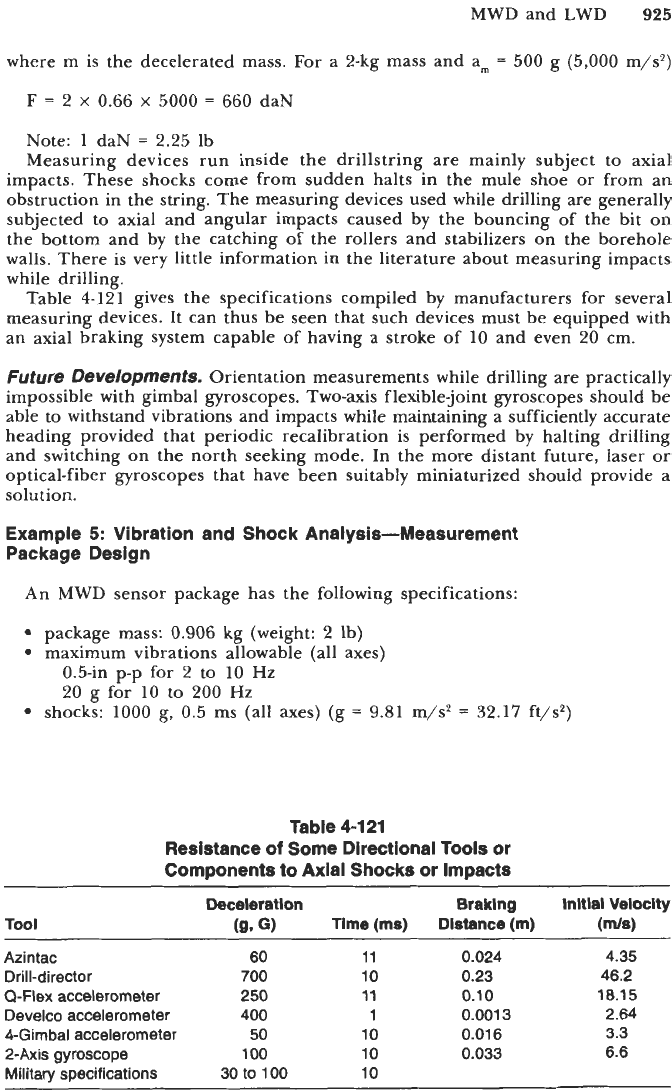
Table
4-12
1
gives the specifications compiled by manufacturers for several
measuring devices. It can thus be seen that such devices must be equipped with
an axial braking system capable of having a stroke of
10
and even
20
cm.
Future Developments.
Orientation measurements while drilling are practically
impossible with gimbal gyroscopes. Two-axis flexible-joint gyroscopes should be
able to withstand vibrations and impacts while maintaining a sufficiently accurate
heading provided that periodic recalibration is performed by halting drilling
and switching on the north seeking mode. In the more distant future, laser
or
optical-fiber gyroscopes that have been suitably miniaturized should provide a
solution.
Example
5:
Vibration and Shock Analysis-Measurement
Package Design
An
MWD
sensor package has the following specifications:
package mass:
0.906
kg
(weight:
2
Ib)
maximum vibrations allowable (all axes)
0.5411 p-p for
2
to
10
Hz
20
g for
10
to
200
Hz
shocks:
1000
g,
0.5 ms (all axes) (g
=
9.81
m/s'
=
32.17
ft/s2)
Table
4-1
21
Resistance
of
Some Directional Tools or
Components to Axial Shocks or Impacts
Tool
Deceleration Braklng Initial Velocity
(9.
G)
Time
(ms)
Distance
(m)
(ds)
Azintac
60
11
0.024
4.35
Drill-director
700
10
0.23 46.2
Develco accelerometer 400
1
0.001
3 2.64
4-Gimbal accelerometer
50
10
0.01
6 3.3
2-Axis gyroscope
100
10
0.033 6.6
Military specifications 30
to
100
10
Q-Flex
accelerometer
250
11
0.10
18.15
926
Drilling and Well Completions
1.
Vz’ibrations:
a. Compute the maximum acceleration that the instrument will accept at
2
and at
10
Hz.
b. Compute the peak to peak motion which can be applied to the instru-
ment at
10
and
200
Hz.
c. Compare the
10-Hz
values. At what frequency will the peak to peak data
of the low frequency be consistent with the acceleration data of the high
frequency?
d. The package is held in a housing with several rubber rings laterally
assumed to behave like perfect springs. Two different ring stiffnesses
are available with total values
of:
100
lb/in
10,000
lb/in
Compute the resonant frequencies for lateral vibrations. In the frequency
range usually encountered in drilling, which one should be used?
Assume that the shock specification refers to the maximum deceleration
(am,) of a half sine wave impact. The mean deceleration will be taken equal
to
0.66
amax.
a. Assuming a dampener in the tool housing exerting a constant force and
the housing stopping abruptly, compute according to the specifications:
the distance of deceleration
9
the velocity at the beginning of the deceleration
the braking force applied to the sensor package
compute:
the braking length for the velocity calculated in a.
the maximum deceleration, is it acceptable?
will such a coil spring be suitable for the vertical vibrations generated
2.
Shocks
along
the borehole
axis
(sensor package axis):
b. Now if the braking force is supplied with a coil spring of
5,000
lb/in.
in rotary drilling?
Solution
1.
a.
0.1
and
2.55
g
b.
3.91
and
0.039
in.
c. At
10-Hz
amplitudes:
0.5
and
3.91
in.;
28
Hz
d.
22
and
221
Hz;
lO,OOO-lb/in. ring more suitable since frequency further
from drilling frequencies
2.
a. d
=
0.03
in.;
v
=
10.6
ft/s; F
=
1320
lb
b. x
=
0.13
in.; a
=
324
g (am
=
491
g); acceptable;
f
=
156
Hz;
acceptable
Example
6:
Vibration and
Shock
Analysis-Mule
Shoe
Engaging
Shock
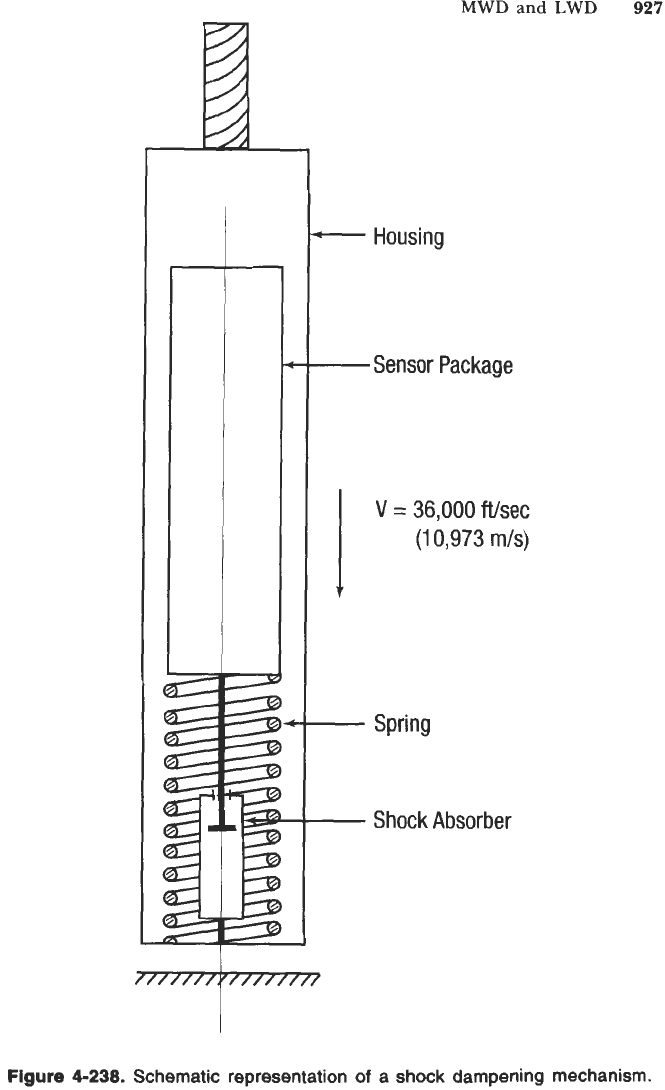
A steering tool sensor and electronic package is mounted in a housing in
Figure
4-238
with a shock absorber and a spring to decrease the value of
deceleration when engaging the mule shoe.
The package has a mass of
2
kg or a weight of
4.415
lb. Assume a downward
velocity of about
10
ft/s. The shock absorber develops a constant force (inde-
pendent
of
the relative velocity) of
10
lb
(44.48
N). The spring stiffness is
57.10
lb/in. The potential energy due to gravity will be neglected.
1.
Taking into account
only
the shock absorber, compute the distance x
traveled by the instrument package with respect to the housing when the
MWD
and
LWD
927
///////,I////////
c
-
Housing
Sensor Package
I
V
=
36,000
Wsec
(1
0,973
m/s)
1
-
Spring
Shock Absorber
-
928
Drilling and Well Completions
housing stops abruptly. Compute the maximum deceleration x in g's
and the deceleration time t. All calculations can be made in English or
metric units.
2.
Taking into account the spring
only
compute the distance traveled x and
the maximum deceleration a in g's when the housing stops abruptly.
3.
Now if both the spring and the shock absorber are acting together, what
will be the distance traveled x and the maximum deceleration a in g's when
the housing stops abruptly?
4.
What is the advantage in adding a shock absorber to the spring in such a
system?
Solution
1.
Neglect the effect of gravity. Energy balance: Fx
=
4
mv2
(v
=
3.048
m/s)
x
=
mv2/2F
=
0.209
m
a
=
F/m
=
22.24
m/s2
=
2.26
g
x
=
+at2
+
t
=
(2~/a)'/~
=
0.137
s
x
=
0.209
m
=
0.685
ft
=
8.23
in.
=
20.9
cm
a
=
2.26
g
t
=
0.137
s
=
137
ms
2.
Before the tool hits, going down at a constant velocity, the spring is already
compressed by the weight of the instrument package,
so
the effect of
gravity can be neglected. Energy balance:
;Smv2
=
+kx2
x
=
(mv2/k)'/'
=
0.043
m
=
0.141
ft
=
1.69
in.
Fma
=
kx
=
430
N
a
=
F/m
=
215
m/s2
=
705.38
ft/s2
=
21.9
g
x
=
0.043
m
=
0.141
ft
=
4.3
cm
=
1.69
in.
a
=
21.9
g
3.
Still neglecting gravity. Energy balance: Fx
+
+kx2
=
+mv2
kx2
+
2Fx
-
mv2
=
0
x
=
[-F
+
(F2
+
kmv2)1/21/k
=
0.0388
m
=
0.127
ft
=
1.53
in.
=
3.88
cm
F,
=
FS
+
1/2
kx
=
432.5
N
a
=
F/m
=
216.2
m/s2
=
709.5
ft/s2
=
22.03
g
x
=
3.88
cm
=
1.53
in.
a
=
22.03
g
4.
Oscillations will be dampened; x slightly decreased:
3.88
cm versus
4.3
cm.
Teledrift and Teleorienter
The first transmission of data during drilling using mud pulses was com-
mercialized by
B.J.
Hughes Inc. in
1965
under the name of
teledrift
and
teleorienter.
Both tools are purely mechanical.
A
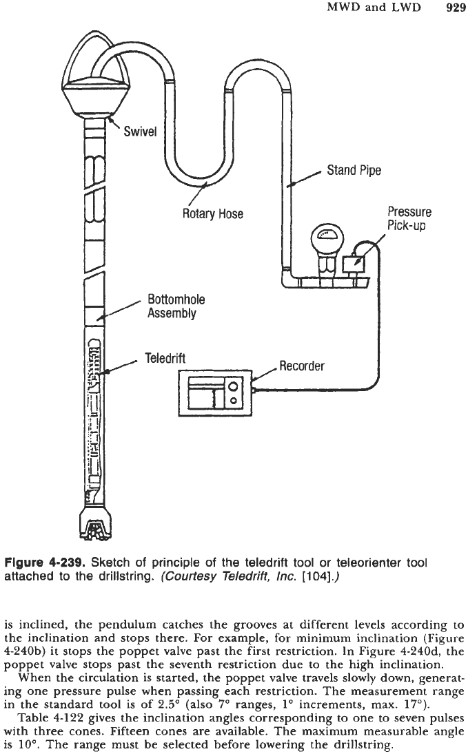
general sketch of principle is
given in Figure
4-239.
The tool is now operated by Teledrift Inc.
The tool generates at bottom positive pulses by restricting momentarily the
flow of mud each time that the mud flow (pumps) is started. The pulses are
detected at surface on the stand pipe and recorded as a function
of
time.
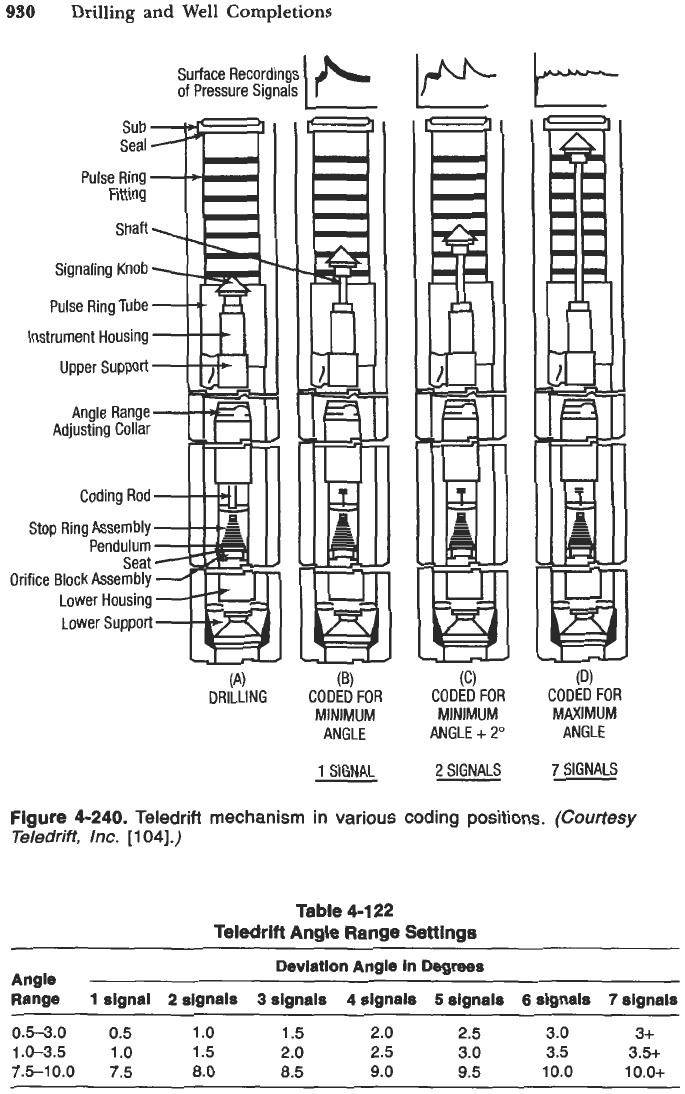
Figure
4-240
shows the sketch of principle of the teledrift unit which is
measuring inclination.
A
pendulum hangs in a conical grooved bore.
A
spring tends to move the
pendulum and the poppet valve upwards when the circulation stops. If the tool
MWD and LWD
929
Pressure
Pick-up
Figure
4-239.
Sketch
of
principle
of
the teledrift tool or teleorienter tool
attached
to
the drillstring.
(Courtesy
Teledrift,
Inc.
[104].)
is inclined, the pendulum catches the grooves at different levels according to
the inclination and stops there.
For
example, for minimum inclination (Figure
4-240b) it stops the poppet valve past the first restriction. In Figure 4-240d, the
poppet valve stops past the seventh restriction due to the high inclination.
When the circulation is started, the poppet valve travels slowly down, generat-
ing one pressure pulse when passing each restriction. The measurement range
in the standard tool
is
of 2.5" (also
7"
ranges,
1"
increments, max. 17").
Table 4-122 gives the inclination angles corresponding to one to seven pulses
with three cones. Fifteen cones are available. The maximum measurable angle
is
IO".
The range must be selected before lowering the drillstring.
930
Drilling and Well Completions
Surface Recordings
of
Pressure Signals
Pulse Ring
Fitting
Shaft
Signaling Knob
Pulse Ring Tube
Instrument Housing
Upper Support
Angle Range
Adjusting Collar
Coding Rod
Stop Ring Assembly
Pendulum
Seat
Orifice Block Assembly
Lower Housing
Lower Support
DRILLING
(B)
CODED
FOR
MINIMUM
ANGLE
1
SIGNAL
I
(C)
CODED
FOR
MINIMUM
ANGLE
+
2"
2
SIGNALS
I
(D)
CODED
FOR
MAXIMUM
ANGLE
7
SIGNALS
Figure
4-240.
Teledrift
mechanism
in
various
coding
positions.
(Courtesy
Teledrift,
lnc.
[
1
041.)
Table
4-1
22
Teledrift Angle Range Settings
Deviation Angle in
Degrees
Angle
Range
1
signal
2
signals
3
signals
4
signals
5
signals
6
signals
7
signals
0.5-3.0
0.5
1
.o
1.5 2.0
2.5
3.0 3+
1.0-3.5
1.0 1.5
2.0
2.5 3.0 3.5 3.5+
7.5-10.0
7.5
8.0
8.5
9.0 9.5 10.0
1
o.o+
MWD
and
LWD
931
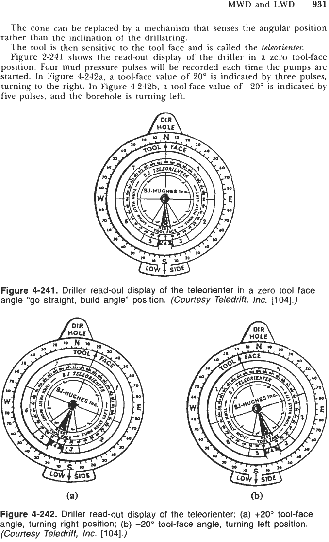
The cone can be replaced by a mechanism that senses the angular position
The tool is then sensitive to the tool face and is called the
teleorienter.
Figure 2-241 shows the read-out display of the driller in a zero tool-face
position. Four mud pressure pulses will be recorded each time the pumps are
started. In Figure 4-242a, a tool-face value of
20"
is
indicated by three pulses,
turning to the right. In Figure 4-24213, a tool-face value
of
-20" is indicated by
five pulses, and the borehole is turning left.
rather than the inclination of the drillstring.
f.;;;\
HOLE
Figure
4-241.
Driller read-out display of the teleorienter in a zero tool face
angle "go straight, build angle" position.
(Courtesy Teledrift,
Inc.
[104].)
Figure
4-242.
Driller read-out display of the teleorienter: (a)
+20°
tool-face
angle, turning right position; (b)
-20"
tool-face angle, turning left position.
(Courtesy Teledrift,
Inc.
[
1
041.)
932
Drilling and Well Completions
These tools have been widely used in the past by the cost conscious operators.
The tool could be rented and operated by the rig floor personnel. However,
the inclination ranges are limited, only one tool, teledrift
or
teleorienter, can
be used during a trip, and only the tool-face angle is read by the teleorienter,
not the azimuth.
These tools are still available but tend to be replaced by the MWD systems.
Mud Pressure and EM Telemetry
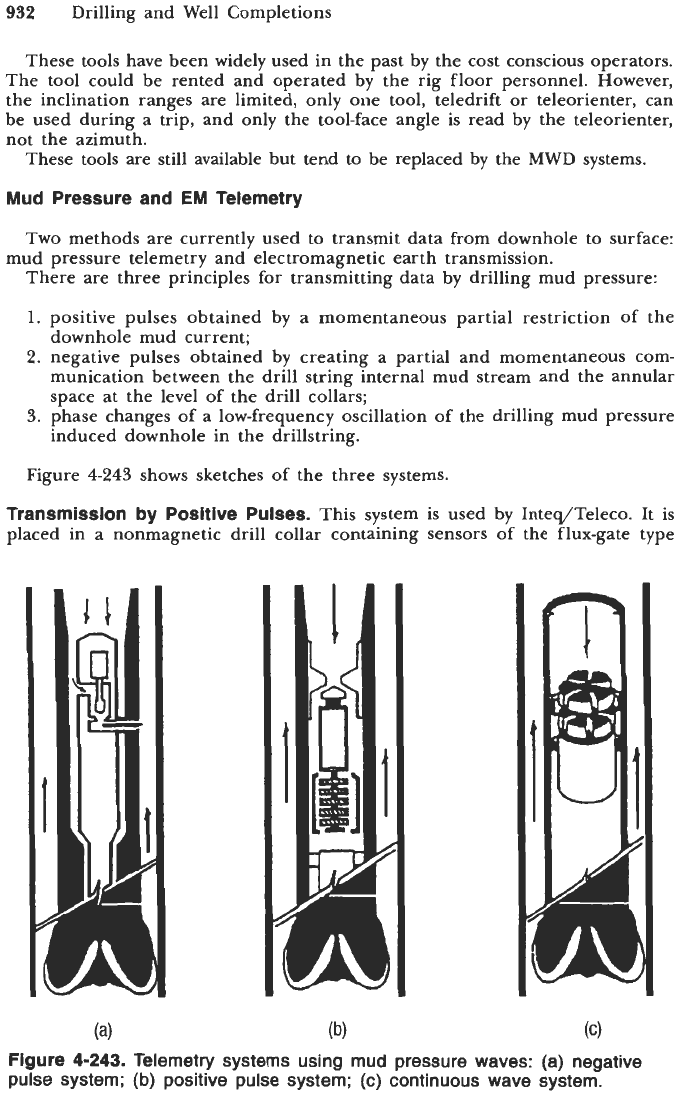
Two methods are currently used to transmit data from downhole to surface:
There are three principles for transmitting data by drilling mud pressure:
1.
positive pulses obtained by a momentaneous partial restriction of the
downhole mud current;
2.
negative pulses obtained by creating a partial and momentaneous com-
munication between the drill string internal mud stream and the annular
space at the level of the drill collars;
3.
phase changes of a low-frequency oscillation of the drilling mud pressure
induced downhole in the drillstring.
mud pressure telemetry and electromagnetic earth transmission.
Figure
4-243
shows sketches of the three systems.
Transmission by Positive Pulses.
This system is used by Inteq/Teleco. It is
placed in a nonmagnetic drill collar containing sensors of the flux-gate type
Figure
4-243.
Telemetry systems using mud pressure waves: (a) negative
pulse system;
(b)
positive pulse system; (c) continuous wave system.
MWD and
LWD
933
for measuring the direction
of
the earth’s magnetic field and accelerometers for
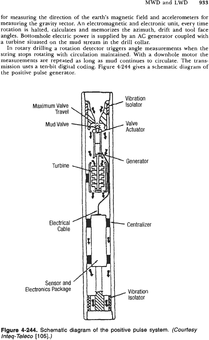
measuring the gravity vector. An electromagnetic and electronic unit, every time
rotation is halted, calculates and memorizes the azimuth, drift and tool face
angles. Bottomhole electric power is supplied by an AC generator coupled with
a turbine situated on the mud stream in the drill collar.
In rotary drilling a rotation detector triggers angle measurements when the
string stops rotating with circulation maintained. With a downhole motor the
measurements are repeated as long as mud continues to circulate. The trans-
mission uses a ten-bit digital coding. Figure
4-244
gives a schematic diagram of
the positive pulse generator.
Maximum Valve
Travel
\
MudValve
-
Turbine
%
Electrical
Cable
Sensor and
Electronics Package
Vibration
Isolator
4
A
Valve
Actuator
.
Generator
-
Centralizer
,
Vibration
Isolator
Figure
4-244.
Schematic diagram
of
the positive pulse system.
(Courtesy
Inteq-Teleco
[105].)
934
Drilling and Well Completions
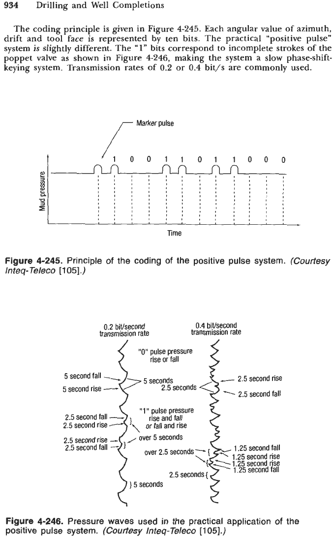
The coding principle is given in Figure
4-245.
Each angular value of azimuth,
drift and tool face is represented by ten bits. The practical “positive pulse”
system is slightly different. The
“1”
bits correspond to incomplete strokes
of
the
poppet valve as shown in Figure
4-246,
making the system a
slow
phase-shift-
keying system. Transmission rates of
0.2
or
0.4
bit/s are commonly used.
Marker pulse
t
011011000
Time
Figure
4-245.
Principle
of
the coding
of
the positive pulse system.
(Courtesy
Inteq-Teleco
[105].)
0.4
biysecond
transmission rate
0.2 biffsecond
transmission rate
iioii
pulse pressure
rise or fall
5 second fall
--r
-
2.5 second rise
5 second rise
-
\
Seco2?dseconds pulse pressure
~
2.5 second fall
2.5 second fall
-
rise
and
fall
2.5 second rise
2.5 second rise
-
J
Over
seconds
2.5 second fall
-
1
-
1.25 second fall
‘{
1 25 second rise
7.25 second fall
’1
or fall and rise
over 2.5 seconds’-{
2.5 seconds
{
-,
.25 second
)
5 seconds
Figure
4-246.
Pressure waves used in the practical application
of
the
positive pulse system.
(Courtesy Inteq-Teleco
11
051.)
