Linden D., Reddy T.B. (eds.) Handbook of batteries
Подождите немного. Документ загружается.

24.28 CHAPTER TWENTY-FOUR
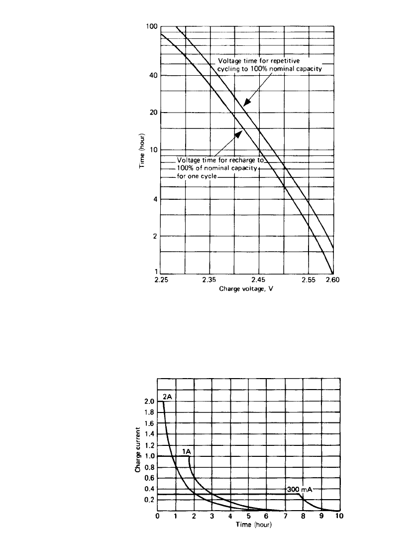
FIGURE 24.33 Charge voltage vs. time on charge at 25⬚C.
FIGURE 24.34 Charge current vs. time at 2.45-V constant
voltage with various current limits (2.5-Ah battery, C / 10 rate).
VALVE REGULATED LEAD-ACID BATTERIES 24.29
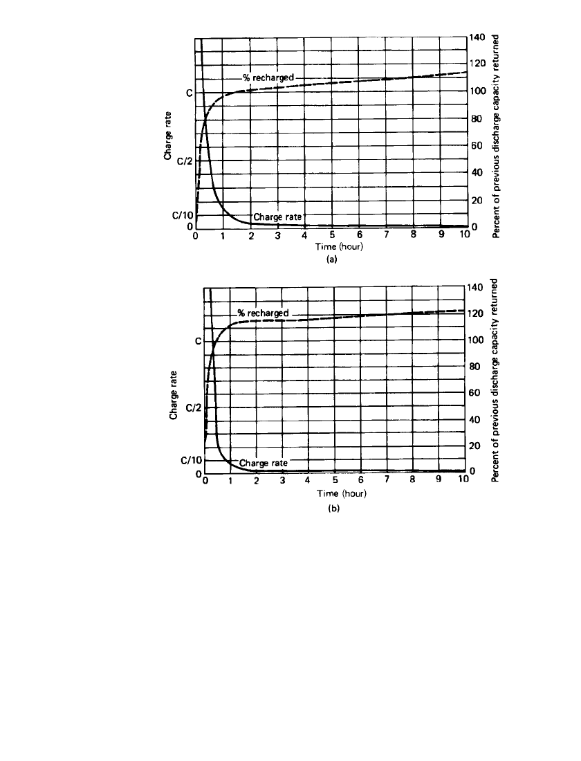
FIGURE 24.35 Charge rate and percent recharged vs. time during con-
stant-voltage charge at 25⬚C. (a) 2.35 V. (b) 2.50 V.
24.5.3 Fast Charging
17
A fast charge is defined as a method of charge that will return the full capacity in less than
4 h. However, many applications require 1 h or less.
Unlike conventional flooded lead-acid batteries, the VRLA design uses a starved electro-
lyte system where most of the electrolyte is contained within a highly retentive separator,
which then creates the starved plates necessary for homogeneous gas-phase transfer. The
gassing problem inherent in conventional lead-acid cells is not evident with this system, as
the oxygen given off on overcharge is able to recombine within the VRLA battery. The large
surface area of the thin plates used in some VRLA batteries reduces the current density to
a level far lower than normally seen in the fast charge of conventional lead-acid batteries,
thereby enhancing the fast-charge capabilities.
24.30 CHAPTER TWENTY-FOUR
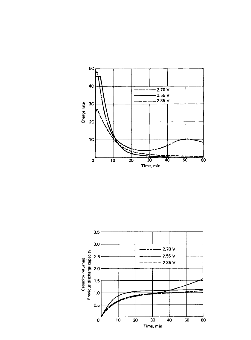
FIGURE 24.37 Charge efficiency vs. time for three charge
voltages.
Figure 24.36 shows the charge rate or the current the VRLA battery can accept for a
1-h charge at three different voltages. The charger has a capability of delivering up to a 5C
charge rate. The battery has a high charge acceptance at the beginning of the charge time:
in fact, in the case of the 2.55-V-per-cell charge, the cell accepted the full current capability
of the charger for the first 3 to 4 min. In the case of the 2.7-V-per-cell charge, there was a
considerable amount of overcharging starting at 30 min, which caused internal heating and
a consequent increase in charge current.
FIGURE 24.36 Charge rate vs. time for three charge voltages.
Figure 24.37 is a set of curves of normalized charge efficiency versus time in minutes
for the three different voltages. This efficiency figure was calculated by dividing the total
Ampere-hour capacity returned by the previous discharge capacity removed. On the 2.55 V
charge, 100% of the capacity removed on the previous cycle was returned in 15 min. With
the 2.7 V charge, a 60% overcharge was returned at the end of the 60-min charge.
VALVE REGULATED LEAD-ACID BATTERIES 24.31
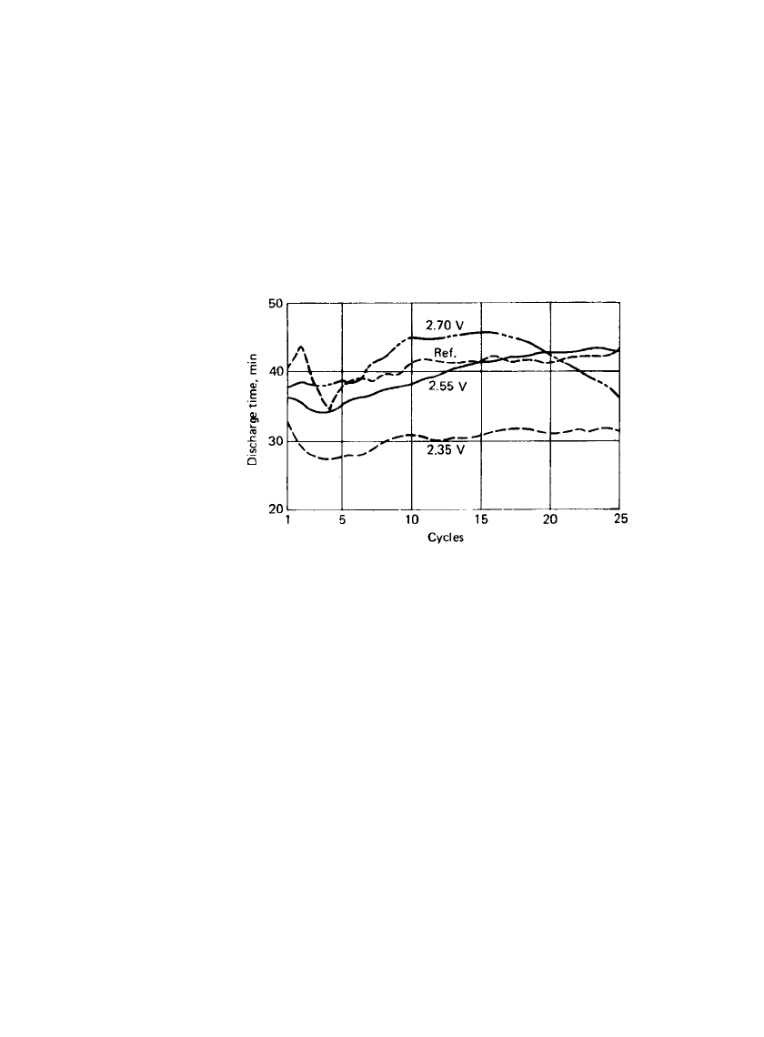
Figure 24.38 plots the discharge time in minutes vs. cycle number for the three charge
voltages. Also, a set of reference batteries was charged at 2.5 V constant voltage for 16 h
and discharged at the 1C rate. This reference curve is displayed to show the expected capacity
at the 1C rate. It can be seen from these data that the 2.55-V-per cell curve most closely
approximates the reference line. The battery charged at 2.7 V per cell received too much
overcharge and, therefore, the capacity degraded after 15 cycles. The battery charged at 2.25
V achieved a value of approximately 75% of the reference and continued to cycle at that
level.
These data show that the thin-plate VRLA battery can be fast-charged to 100% of the
rated capacity in less than 1 h. A constant-voltage charger set at 2.5 to 2.55 V per cell and
capable of the 3C to 4C rate of charge is preferred. It should be noted, as discussed, that
charging at 2.7 V per cell for prolonged periods will damage the battery.
FIGURE 24.38 Effect of cycling on discharge time for three
charge voltages.
24.5.4 Float Charging
When the VRLA battery is to be float-charged as in a standby application, the constant-
voltage charger should be maintained between 2.3 and 2.4 V for maximum life. Continuous
charging at greater than 2.4 V per cell is not recommended because of accelerated grid
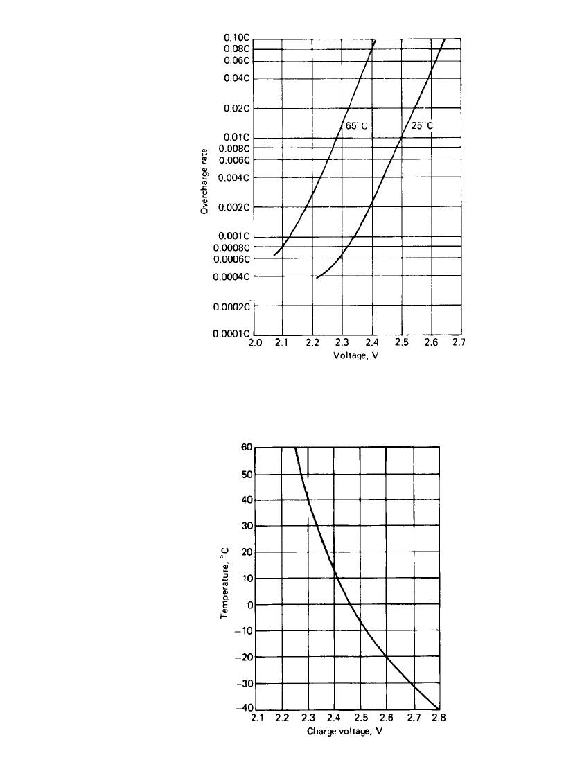
corrosion. Figure 24.39 gives the approximate values of voltage a battery will attain when
float-charged at 25 and 65
⬚C, or the charge rate a battery will accept if it has been charged
for a sufficient period of time so that it is in a state of overcharge equilibrium. These curves
can also be used to determine the approximate value of continuous constant current (trickle
charge) that will maintain the proper float voltage. As an example, if a battery were trickle-
charged at the 0.001C rate, its average voltage per cell on overcharge would be 2.35 V at
25
⬚C. Conversely, if a cell were constant-voltage-charged at 2.35 V, its overcharge rate would
be 0.001C.
High temperatures accelerate the rate of the reactions which reduce the life of a battery.
At increased temperatures, the voltage necessary for returning full capacity in a given time
is reduced because of the increased reaction rates within the battery. To maximize life, a
negative charging temperature coefficient of approximately
⫺2.5 mV/⬚ C per cell is used at
temperatures significantly different from 25
⬚C. Figure 24.40 shows the recommended charg-
ing voltage at various temperatures for a sealed battery float-charged at 2.35 V per cell at
25
⬚C. It is obvious from this curve that at extremely low temperatures, a significantly greater
temperature coefficient than
⫺2.5 mV/⬚C is required to achieve full recharge of the cell.
Figure 24.40 also shows the voltage compensation under cycling service. The voltage com-
pensation keeps the charging current at about the same value that it would be at 25
⬚C when
24.32 CHAPTER TWENTY-FOUR
FIGURE 24.39 Overcharge current and voltage.
FIGURE 24.40 Recommended charge voltage
at various temperatures (temperature compensa-
tion.)
VALVE REGULATED LEAD-ACID BATTERIES 24.33
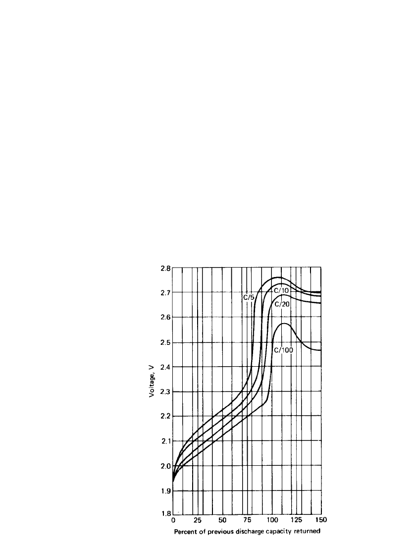
FIGURE 24.41 Voltage curves for batteries charged
at various constant-current rates at 25⬚C.
the battery temperature is different. Temperature compensation of the charging voltage pre-
vents thermal runaway of the batteries when they are used at high temperatures and assures
adequate charging if the battery temperature is low.
When trickle-charging, it may be necessary to increase the charge rate at higher temper-
atures to maintain the proper float voltage. From Fig 24.39, it can be seen that for a battery
trickle-charged at the 0.001C rate at 25
⬚C, the float voltage would be 2.34 V. However, at
the same rate at 65
⬚C, the float voltage would be approximately 2.12 V, which is below the
open-circuit voltage of the cell. At 65
⬚C the trickle-charge current would need to be increased
to approximately 0.01C to maintain the proper float voltage.
24.5.5 Constant-Current Charging
Constant current is another efficient method of charging the VRLA battery. Constant-current
charging is accomplished by the application of a nonvarying constant-current source. This
charge method is especially effective when several cells are charged in series, since it tends
to eliminate any charge imbalance in a battery. Constant-current charging charges all cells
equally because it is independent of the charging voltage of each cell in the battery. Figure
24.41 shows a family of curves of battery voltage versus percent capacity of previous dis-
charges returned at different constant-current charging rates. As shown by these curves at
different charge rates, the voltage increases sharply as the full charge state is approached.
This increase in voltage is caused by the plates going into overcharge when most of the
24.34 CHAPTER TWENTY-FOUR
active material on the plates has been converted from lead sulfate to lead on the negative
plate and to lead dioxide on the positive plate. The voltage increase will occur at lower
states of charge when the cell is being charged at higher rates. This is because at the higher
constant-current charge rates the charging efficiency is reduced. The voltage curves in Fig.
24.41 are somewhat different from those for a conventional lead-acid battery due to the
effect of the recombination of gases on overcharge within the system. The VRLA battery is
capable of recombining the oxygen produced on overcharge up to the C /3 rate of constant-
current charge. At higher rates the recombination reaction is exceeded by the rate of gas
generation.
While constant-current charging is an efficient method, continued application at rates
above C /500, after the battery is fully charged, can be detrimental to life. At overnight
charge rates (C/10 to C /20), the large increase in voltage at the nearly fully charged state
is a useful indicator for terminating or reducing the rates for a constant-current charger. If
the rate is reduced to C /500, the battery can be left connected continuously and give 8 to
10 years of life at 25
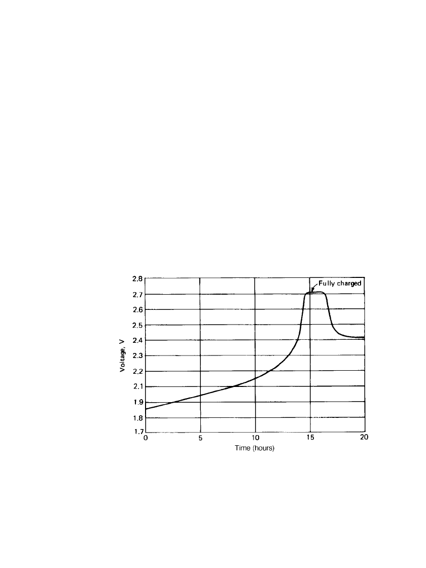
⬚C. Figure 24.42 is a plot of voltage versus time for a battery charging
at the C /15 rate of constant current at 25
⬚C. This battery had previously been discharged to
100% depth of discharge at the C /5 rate. This curve shows that the battery is not fully
charged at the time the voltage increase occurs and must receive additional charging. If a
battery is to be charged with constant current at higher than room temperature, then some
temperature compensation must be built into the voltage-sensing network. As explained in
Sec. 24.5.4, at higher temperatures and given charging rates, the battery voltage on over-
charge is reduced. Therefore the rise in voltage at close to full charge will be somewhat
depressed.
FIGURE 24.42 Constant-current charge at C/ 15 rate, 25⬚C.

VALVE REGULATED LEAD-ACID BATTERIES 24.35
24.5.6 Taper-Current Charging
Although taper-current chargers are among the least expensive types of chargers, their lack
of voltage regulation can be detrimental to the cycle life of any type of battery. The VRLA
battery can withstand charge voltage variations, but some caution in using taper-current
chargers is recommended. A taper-current charger contains a transformer for voltage reduc-
tion and a half- or full-wave rectifier for converting from alternating to direct current. The
output characteristics are such that as the voltage of the battery increases during charge, the
charging current decreases. This effect is achieved by use of the proper wire size and the
turns ratio. Basically, the turns ratio from primary to secondary determines the output voltage
at no load, and the wire size in the secondary determines the current at a given voltage. The
transformer is essentially a constant-voltage transformer which depends entirely on the AC
line voltage regulation for its output-voltage regulation. Because of this method of voltage
regulation, any changes in input line voltage directly affect the output of the charger. De-
pending on the charger design, the output-to-input voltage change can be more than a direct
ratio; for example, a 10% line-voltage change can produce a 13% output-voltage change.
When considering the cost advantage of using a half-wave rectifier versus a full-wave
rectifier in a taper-current charger, it should be noted that the half-wave rectifier supplies a
50% higher peak-to-average-voltage ratio than the full-wave rectifier. Therefore the total life
of the battery for a given average charge voltage can be reduced for the half-wave type of
charger because of the higher peak voltages. A DC ripple can lead in time to decreased
performance through degradation of the active material and the grid. An AC ripple can be
a more significant factor in premature battery failure, especially in float or uninterruptible
power systems. The repeated charging and discharging of the battery shortens the battery
life through heat generation and corrosion.
There are several charging parameters which must be met. The parameter of main concern
is the recharge time to 100% nominal capacity for cycling for applications. This parameter
can primarily be defined as the charge rate available to the battery when each cell is at 2.2
and 2.5 V. The charge voltage at which approximately 50% of the charge has been returned
to the battery at normal charge rates of C /10 to C/ 20 is 2.2-V-per-cell; the 2.5 V per cell
point represents the voltage at which the battery is in overcharge. Given the charge rate at
2.2 V, the recharge time for a taper-current charger can be defined by
1.2
⫻ capacity discharged previously
Recharge time ⫽
charge rate at 2.2 V
It is recommended that the charge rate at 2.5 V be between C/ 50 maximum and C /100
minimum to ensure that the battery will be recharged at normal rates and will not be severely
overcharged if the charger is left connected for extended time periods.
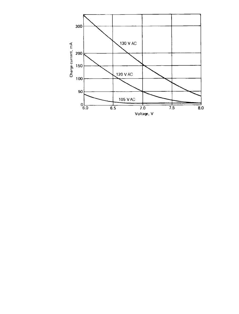
Figure 24.43 is a set of output voltage versus current curves for a typical 2.5-Ah-battery
taper-current charger. The three curves show the change in output with a variation in input
voltage from 105 to 130 V AC. This particular charger, at 120-V AC input, will charge a
three-cell D-sized battery (rated at 2.5 Ah) which had been previously discharged to 100%
depth of discharge in 30 h by the following equation:
1.2
⫻ 2.5
Recharge time ⫽⫽30 h
0.100 A
24.36 CHAPTER TWENTY-FOUR
FIGURE 24.43 Taper-current charger characteristics for 2.5-Ah cylin-
drical three-cell VRLA battery.
24.5.7 Parallel/Series Charging
VRLA batteries can be charged or discharged in parallel. When more than four strings of
cells are paralleled, it is advisable to use diodes in both the charge and the discharge path
in the circuit. The discharge diodes prevent a battery from discharging into a paralleled
battery should a cell short-circuit in the battery. The charge diodes, in conjunction with the
fuse, will prevent a battery with a short-circuited cell from accepting all the charge current
from the charger and subsequently prevent the other paralleled batteries from being fully
charged. The fuse should be sized by dividing the maximum charge current by the number
of batteries in parallel and multiplying this value times 2. This should result in the fuse
opening on charge in a parallel string which has a short-circuited cell.
When float-charging many cells in series, 12 or more, for example, it is advantageous to
use a trickle charge of C/500 maximum in parallel with the float charger. This trickle charge
will tend to balance all cells in the battery by driving a continuous trickle charge equally
through all cells.
24.5.8 Charge-Current Efficiency
Charge-current efficiency is the ratio of the current that is actually used for electrochemical
conversion of the active material from lead sulfate to lead and lead dioxide to the total
current supplied to the cell on recharge. The current which is not used for charging is
consumed in parasitic reactions within the cell such as corrosion and gas production.
The charging efficiency is high for a VRLA battery. The distinctly high ratio of plate
surface area to Ampere-hour capacity allows for higher charging rates and, therefore, efficient
charging.
Charge-current efficiency is a direct function of the state of charge. The charge efficiency
of a battery is high until it approaches full charge, at which time the overcharge reactions
begin and the charge efficiency decreases. Obviously, past the point of full recharge, the
efficiency falls to zero.
VALVE REGULATED LEAD-ACID BATTERIES 24.37
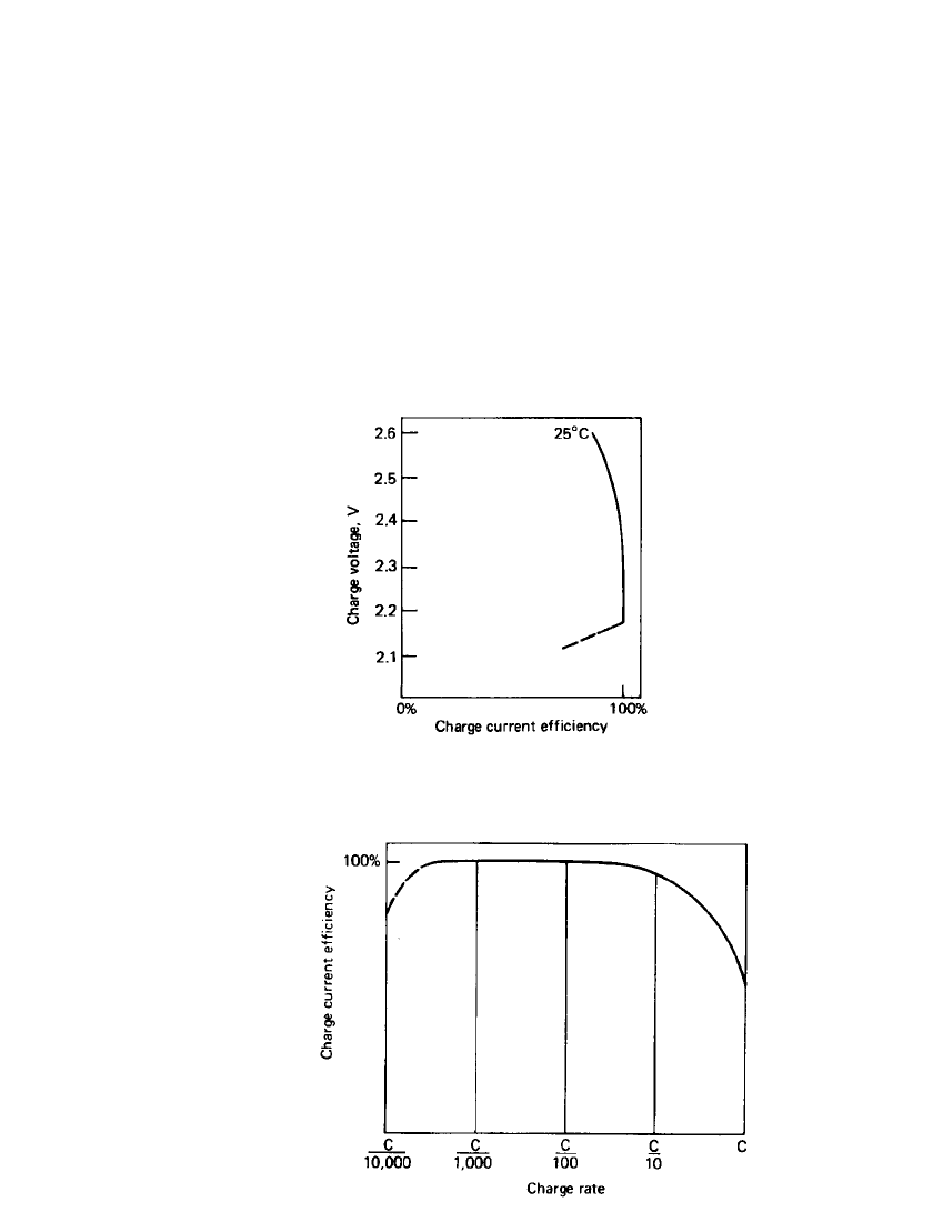
Figure 24.44 is a curve of charge current efficiency versus voltage at various constant
voltages. Increasing voltage decreases the efficiency because of increased parasitic currents.
The efficiency shows a marked decrease below the open-circuit voltage, typically 2.15 to
2.18 V, because the charge voltage is not high enough to support the charging reaction.
Figure 24.45 is a curve of efficiency versus log rate at various constant-current charge
rates. As can be seen from the curve, at rates up to C/ 10 the efficiency approaches 100%.
At higher rates there is a decrease in efficiency because, as the cell approaches the fully
charged state, the surfaces of the plates become fully charged. This increases the charging
reaction rates and results in increased voltages and gassing. At low charge rates, the efficiency
drops because the charge current is equivalent to the parasitic currents and the battery voltage
approaches the open-circuit value.
Figure 24.46 shows the charge acceptance during charge at various temperatures and
charge rates.
FIGURE 24.44 Constant-voltage charge efficiency.
FIGURE 24.45 Constant-current charge efficiency.