Linden D., Reddy T.B. (eds.) Handbook of batteries
Подождите немного. Документ загружается.


20.2 CHAPTER TWENTY
In the reserve construction, the electrolyte is physically separated from the electrode active
materials until the battery is used and it is stored in a reservoir prior to activation. This
design feature provides a capability of essentially undiminished output even after storage
periods, in the inactive state, of over 14 years. The reserve feature, however, results in an
energy density penalty of as much as 50% compared with the active lithium primary batteries.
Key contributors to this penalty are the activation device and the electrolyte reservoir.
In the selection of a lithium anode electrochemical system for packaging into a reserve
battery, besides such important considerations as physical properties of the electrolyte so-
lution and performance as a function of the discharge conditions, factors such as the stability
of the electrolyte and the compatibility of the electrolyte with the materials of construction
of the electrolyte reservoir are of special importance.
20.2 CHEMISTRY
20.2.1 Lithium/Vanadium Pentoxide (Li / V
2
O
5
) Cell
The basic cell structure of this system consists of a lithium anode, a microporous polypro-
pylene film separator, and a cathode that is usually composed of 90% V
2
O
5
and 10% graphite,
on a weight basis. When it is used in a reserve battery, the prevalent electrolyte is 2M LiAsF
6
⫹ 0.4M LiBF
4
in methyl formate (MF) because of its excellent stability during long-term
storage.
As shown in Fig. 20.1, the Li/V
2
O
5
system has a two-plateau discharge characteristic. A
net cell reaction, involving the incorporation of lithium in V
2
O
5
, has been postulated to
account for the first plateau,
Li
⫹ VO → LiV O
25 25
The initial voltage level ranges from 3.4 to 3.3 V, decreases to 3.3 to 3.2 V for approximately
50% of the active life of the first discharge plateau, at which point the range again decreases
to a level of 3.2 to 3.1 V, which is maintained for the balance of the first plateau of discharge.
After completion of the first plateau, the Li/V
2
O
5
system undergoes a rapid change in voltage
to the second discharge plateau around a voltage range of 2.4 to 2.3 V. This step involves
the formation of reduced forms of V
2
O
5
, although specific mechanisms remain unclear.
1
This
second plateau is relatively more sensitive to temperature and discharge rate, and it is for
this reason that most Li/V
2
O
5
cells (active and reserve) are designed to operate at only the
first discharge plateau level.
2
The long-term storage capability of Li/V
2
O
5
reserve cells is heavily dependent on the
stability of the electrolyte solution. LiAsF
6
in MF electrolyte is unstable due to the decom-
position reactions involving the hydrolysis of methyl formate followed by the dehydration
of the hydrolysis product(s).
3
These reactions result in a premature fracture of the glass
ampoule used as the electrolyte reservoir. The stability of the LiAsF
6
:MF electrolyte solution
was achieved by making the solution either neutral or alkaline. In practiced, this is accom-
plished by using two electrolyte salts (LiAsF
6
⫹ LiBF
4
:MF) and by incorporating lithium
metals to scavenge water in the glass ampoule.
20.2.2 Lithium/Thionyl Chloride (Li /SOCl
2
)
The basic cell structure that is generally used for this system consists of a lithium anode, a
nonwoven glass separator and a Teflon
-bonded carbon cathode which serves only as the
reaction site medium. One unique feature of this chemistry is the fact that thionyl chloride
(SOCl
2
) serves two functions—as the solvent of the commonly used LiAlCl
4
in SOCl
2
elec-
trolyte solution and as the active cathode material (see Sec. 14.6).

AMBIENT-TEMPERATURE LITHIUM ANODE RESERVE BATTERIES 20.3
Figure 20.1 shows the marked advantage in discharge performance of the Li /SOCl
2
sys-
tem. The accepted net cell reaction for this system is
4Li
⫹ 2SOCl → 4LiCl ⫹ S ⫹ SO
22
Most of the sulfur dioxide formed during discharge is dissolved in the electrolyte and prac-
tically no gas pressure is generated.
4
Depending on the discharge rate and temperature the
Li/ SOCl
2
system normally exhibits a working voltage range of between 3.0 and 3.6 V with
a flat discharge characteristic. These excellent discharge characteristics—high voltage and
flat discharge—are best attained in a reserve cell, especially is the discharge current density
is high. In an active primary Li /SOCl
2
cell, the lithium anode is coated with a passive LiCl
film. Under sustained storage coupled with high-temperature exposure the passivating film
will limit the current-handling capability of the anode as well as increasing the time required
to reach operating voltage.
4
The conventional LiAlCl
4
in SOCl
2
electrolyte solution has proved to have excellent
stability. Electrolyte glass ampoules exposed to
⫹74⬚C did not show any sign of apparent
degradation up to at least 12 years of storage. Because of this and its overall performance
superiority, the Li/ SOCl
2
reserve cell has become the system of choice for high-energy
reserve batteries.
Recently the use of excess AlCl
3
, a Lewis acid, in the conventional LiAlCl
4
in SOCl
2
electrolyte solution was shown to improve the rate capability of the Li/SOCl
2
system.
5,6
It
should be noted, however, that the inherent stability of this high-rate electrolyte has yet to
be established so as to ensure its application in reserve cells.
20.2.3 Lithium/Sulfur Dioxide (Li/ SO
2
)
The Li/ SO
2
system uses a basic cell structure consisting of a lithium anode, a separator, and
a Teflonated
carbon cathode, similar to one used in the Li /SOCl
2
system, which serves as
the reaction site. The electrolyte solution commonly employed contains a mixture of lithium
bromide (LiBr), acetonitrile (AN), and sulfur dioxide (SO
2
), which also serves as the active
cathode material.
One serious problem in using the LiBr in AN–SO
2
electrolyte solution for reserve cells
is its instability during storage. Although this electrolyte solution is commonly employed in
active primary cells, it is unsuitable for reserve battery applications because it decomposes
to form highly reactive and solid products when stored in the absence of cell components.
Replacing LiBr with lithium hexafluoroarsenate (LiAsF
6
) results in an electrolyte solution
with good stability. The functional performance of the LiAsF
6
electrolyte is equivalent or
superior to that of the LiBr solution for low to moderate rate.
7–9
.
The Li/SO
2
reserve battery, using the stable electrolyte solution (LiAsF
6
in AN-SO
2
),
follows the same net cell reaction
2Li ⫹ 2SO → LiSO ↓
2224
as in the active primary cell. It should be noted, however, that LiAsF
6
in AN–SO
2
electrolyte
solution is limited to moderate- or lower-rate applications due to poorer electrolyte conduc-
tivity. Because of this, the emphasis on using the Li/SO
2
system for reserve applications
has been shifted to the higher-performance Li /SOCl
2
system.

20.4 CHAPTER TWENTY
20.2.4 Lithium/Pre-Charged Li
x
CoO
2
(0.5 ⱕ x ⬍ 1) Cell
The use of pre-charged Li
x
CoO
2
is a new approach to high-voltage and high-energy cathode
systems for reserve battery applications. Key criteria are the ability to process the cathode
materials into a stable raw material for the reserve cells. In the case of the Li
x
CoO
2
cathode,
lithium can be extracted electrochemically to where x
ⱖ 0.5 and then processed successfully
as a raw material for primary active cell applications.
10
The Li /pre-charged Li
x
CoO
2
(0.5 ⱕ
x ⬍ 1) cell structure is very similar to the Li/ V
2
O
5
cell. Except for the difference in cathode
material, all other design features are essentially the same.
Both the Li /V
2
O
5
and Li/pre-charged Li
x
CoO
2
(0.5 ⱕ x ⬍ 1) cells offer an unique design
feature, permitting the cells to be recharged when demanded by a specific application. One
application that used the pre-charged Li
x
CoO
2
cathode technology is described in Sec. 20.3.2.
20.3 CONSTRUCTION
20.3.1 General Considerations
Lithium anode reserve batteries are basically composed of three major components:
1. Activation and electrolyte delivery system
2. Electrolyte reservoir
3. Cell and/ or battery unit
However, the actual design can vary widely, depending on the application. The design can
vary from a simple, small, single cell with an ampoule manually activated, to a very large,
complex, multicell battery with an automatic electric initiation mechanism to transfer the
electrolyte from the reservoir chamber to a high-voltage multicell battery stack. Both the
electrodes and the hardware components are essentially the same as the primary active units,
but with allowances made for electrolyte storage and electrolyte delivery into the cells at the
time of activation. In addition, the electrochemical and hardware components must be con-
structed of a rugged maintenance-free design to survive severe environmental and perform-
ance requirements as most are used in military or special applications. For example, Table
20.1 lists typical requirements of lithium reserve batteries and illustrates the reason for many
of their unique construction and design features.
TABLE 20.1 Typical Characteristics of Lithium
Anode Reserve Batteries
Operating temperature range ⫺55 to 70⬚C
10- to 20-year unactivated storage life
Hermetically sealed
High energy density
High reliability
Low electrical noise
Flat discharge voltage profile
Rapid voltage rise after initiation
Mechanical environmental capability:
Acceleration shocks up to 20,000 g
High spin up to 20,000 rpm
Transportation and deployment vibration levels
Operating life from several seconds up to 1 year

AMBIENT-TEMPERATURE LITHIUM ANODE RESERVE BATTERIES 20.5
Some common construction features are used in the design of lithium reserve batteries.
The outer case is generally made of a 300-series stainless steel since it offers the corrosion
resistance against both the internal system and the external environment during its long-term
use. Various welding techniques such as laser, tungsten inert gas (TIG), resistance, and
electron beam can be applied to the 300-series stainless steels. Thus the outer case provides
a true 20-year reliability, capable of maintaining the hermeticity required for reserve lithium
batteries. The electrical terminals used are generally glass-to-metal types, which also provide
the hermeticity required for long-term storage.
20.3.2 Types of Lithium Anode Reserve Batteries
Three basic lithium reserve battery types are being manufactured at the present time:
1. Single-cell battery with electrolyte stored in a glass ampoule
2. Multiple single cells using bellows for the electrolyte storage reservoir
3. Multicells of bipolar construction with either a glass ampoule or a reservoir for electrolyte
storage
Ampoule Type. Single-cell reserve types using an ampoule as the electrolyte storage res-
ervoir are the most reliable of the reserve designs due to their simple construction and lack
of intercell leakage problems associated with multicell batteries. One group of these cells is
sized to the ANSI standard specifications, and the other group consists of those cells built
for special-purpose applications which are not sized to the ANSI specifications. Both groups,
however, are very similar in construction.
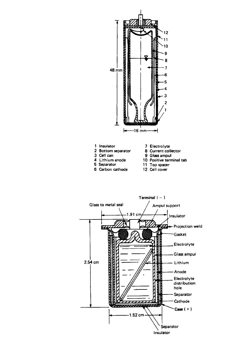
Figure 20.2 shows the cross section of a reserve lithium anode cell in an A-size config-
uration of about 1 Ah, using the Li/ SOCl
2
system.
6
The cell consists of concentrically
arranged components. A lithium anode is swaged against the inner wall of a stainless-steel
cylindrical can. A nonwoven glass separator is located adjacent to the anode. The Teflon
-
bonded carbon cathode is inserted against the separator. A cylindrical nickel current collector
provides the electrical contact to the positive terminal and houses the hermetically sealed
glass ampoule. The ampoule is held firmly in place by upper and lower insulating supports,
which protect it from premature breakage while permitting transmission of a direct force at
the bottom of the case to shatter the ampoule at the time of activation. The unit is sealed
hermetically to ensure long shelf life in the unactivated condition. Activation is achieved by
applying a sharply directed force at the bottom of the cell case to shatter the glass ampoule.
The electrolyte is absorbed by the porous cathode and the glass separator, thereby activating
the battery.
Another design has been developed for mine and fuze applications, using both the
Li/V
2
O
5
and the Li /SOCl
2
systems, in the capacity range of 100 to 500 mAh.
11
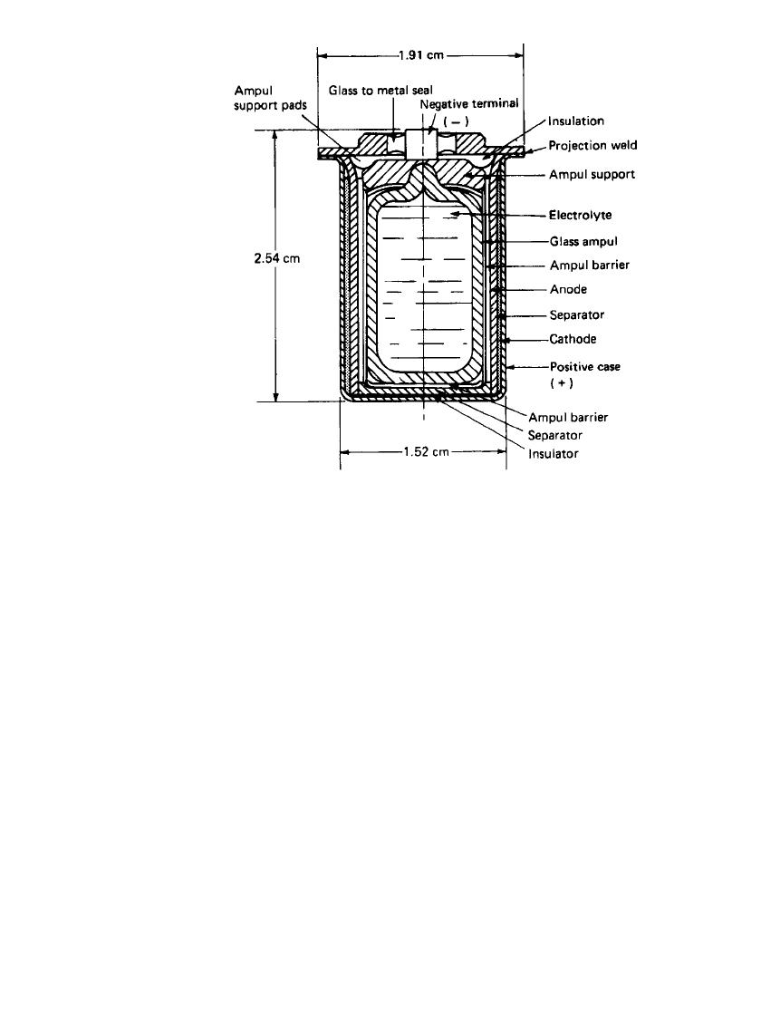
The cross
sections of these two cells are shown in Figs. 20.3 and 20.4 respectively. Both cells are
similar with respect to the external hardware and the internal arrangement of the components.
The case and header assembly are projection-welded together at the case flange. The header
serves as the cover for the cells and incorporates a glass-to-metal seal for the center terminal
pin made of nickel-iron Alloy52. The terminal pin has negative polarity (both cell designs),
and the balance of the header and case surface have positive polarity. The hermetically sealed
hardware in conjunction with the reserve feature of the design makes it possible to achieve
storage times in excess of 20 years.
The internal arrangement of the components consists of annularly located electrodes about
a central glass ampoule used as the electrolyte solution reservoir. In addition there are various
insulating components in the upper and lower portions of the cell, used to prevent internal
short-circuiting.
20.6 CHAPTER TWENTY
FIGURE 20.2 Cross section of Li / SOCl
2
A-size re-
serve cell. (Courtesy of Tadiran Industries, Ltd.)
FIGURE 20.3 Cross section of Li / V
2
O
5
reserve cell. Alliant
model G2659. (Courtesy of Alliant Techsystems, Inc.)
AMBIENT-TEMPERATURE LITHIUM ANODE RESERVE BATTERIES 20.7
FIGURE 20.4 Cross section of LiSOCl
2
reserve cell. Alliant
model G2659B1. (Courtesy of Alliant Techsystems, Inc.)
Several features account for most of the design differences between these two cells. In
the Li/SOCl
2
reserve cell, the glass ampoule also contains the cathode oxidant, SOCl
2
, while
the cathode oxidant of the Li /V
2
O
5
reserve cells is contained in the cathode structure. Di-
rectly adjacent to the Li/SOCl
2
cell case is the Teflonated carbon, while in the case of
the Li /V
2
O
5
cell, the cathode is molded from a dry mixture of V
2
O
5
and graphite. The
Teflonated
-carbon cathode for the reduction of SOCl
2
is made in sheet form and is attached
to a metal grid rolled to shape and inserted against the inside wall of the case. Another
difference is the way the electrical connection is made for the two cathodes. The V
2
O
5
connection is made by the direct-pressure contact of the molded cathode, whereas with the
SOCl
2
system the cathode lead is welded to the case at the time the cover is welded. The
lithium anode structure consists of pure lithium metal, which is pressed onto an expanded
metal grid of 316L stainless steel. One end of a flat 316L stainless-steel lead is spot-welded
to the pin of the glass-to-metal seal. Rolled into a cylinder, the anode is inserted into the
cell next to the separator. Both cells are provided with an ampoule support in order to survive
the shock environment specified. In the Li /SOCl
2
system, Tefzel and glass have been found
to be chemically stable for use as insulators, separators, and supports. The Li /V
2
O
5
system
allows more flexibility because many rubbers and plastics can be used.
Multicell Single-Activator Design. For those applications where higher than single-cell
voltages are required, a battery is constructed of two or more cells, depending, of course,
on the voltage needed. Typical voltages are 12 and 28 V, and for lithium anode cells with a
2.7 to 3.3-V operating voltage, this would require anywhere from 4 to 10 cells for each
battery. This family of batteries is unique with respect to the method of cell activation and
the containment of electrolyte in multiple cells initiated from a single self-contained reservoir
of electrolyte. Batteries of this design are used in preference ot the bipolar type to achieve
higher cell capacities and to allow discharge times up to 1 year or more, through the tight
20.8 CHAPTER TWENTY
control of intercell leakage. The leakage currents are controlled and limited to usually less
than several percent of the discharge current. This feature, however, limits these batteries
from being miniaturized, which is possible with many bipolar designs.
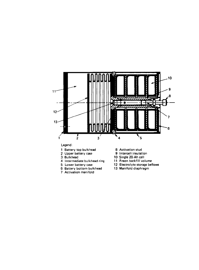
An example of this design approach is the Li /SO
2
reserve battery illustrated in Fig. 20.5.
The battery is cylindrical and contains three main components: (1) the electrolyte storage
reservoir section, (2) the electrolyte manifold and activation system, and (3) the reserve cell
compartment. About one-half of the internal battery volume contains the electrolyte reservoir.
The reservoir section consists primarily of a collapsible bellows in which the electrolyte
solution is stored. Surrounding the bellows, between it and the outer battery case, is a space
that holds a specific amount of gas /liquid. The gas is selected such that its vapor pressure
always exceeds that of the electrolyte, thereby providing the driving force for eventual liquid
transfer into the cell chamber section once the battery has been activated.
FIGURE 20.5 Cross section of 20-Ah Li /SO
2
multicell battery.
In the remaining half of the battery volume there is the centrally located electrolyte
manifold and activation system housed in a 1.588-cm-diameter tubular structure plus the
series stack of four torroidally shaped cells that surround the manifold/ activation system.
The manifold and cells are separated from the reservoir by an intermediate bulkhead. In
the bulkhead there is a centrally positioned diaphragm of thin section to be pierced by the
cutter contained within the manifold. In fabrication, the diaphragm is assembled as part of
the tubular manifold which, in turn, is welded as a subassembly to the intermediate bulkhead.
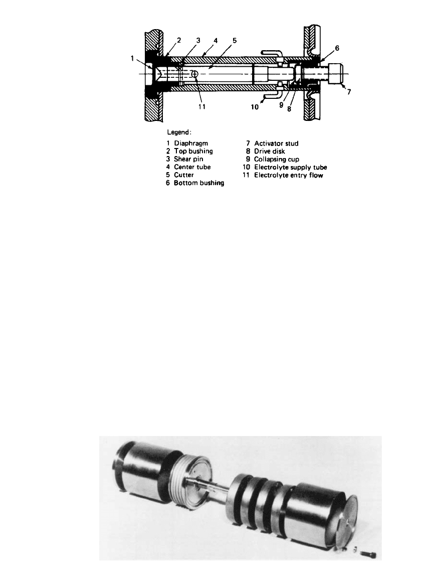
Figure 20.6 is a more detailed cross-sectional view of the electrolyte manifold and activation
system with the major components identified.
The activating mechanism consists of a cutter that is manually moved into the diaphragm,
cutting it and thereby allowing electrolyte to flow. The movement of the cutter is accom-
plished by the turning of an external screw that is accessible in the bottom base of the
battery. The cutter section and the screw mechanism are isolated from one another by a
small collapsible metal cup that is sealed hermetically between the two sections. This pre-
vents external electrolyte leakage. The manifold section is a series of small nonconductive
plastic tubes connected to one end of the central cylinder and to each of the individual cells
at the other end. The long length and small cross-sectional area of the tubes minimize
intercell leakage losses during the period of time that electrolyte is present in the manifold
structure.
AMBIENT-TEMPERATURE LITHIUM ANODE RESERVE BATTERIES 20.9
FIGURE 20.6 Cross section of electrolyte manifold and activa-
tion system.
FIGURE 20.7 Pictorial view of 20-Ah Li / SO
2
multicell battery.
In this application four individual cells are required to meet the voltage requirement. (The
number of cells is, of course, adjustable with minor modification to meet a wide range of
voltage needs.) Each cell contains flat circular anodes and cathodes that are separately wired
in parallel to achieve the individual cell capacity and plate area needed for a given set of
requirements. To fabricate, the components, with intervening separators, are alternately
stacked around the cell center tube, after which the parallel connections are made. The cells
are individually welded about the inner tube and outer perimeter to form hermetic units
ready for series stacking within the battery. Connections from the cells are made to external
terminals which are located in the bottom bulkhead of the battery.
Figure 20.7 shows the major battery components prior to assembly. The components
shown are fabricated primarily from 321 stainless steel, and the construction is accomplished
with a series of TIG welds. The hardware shown is designed specifically for use with the
lithium/ sulfur dioxide electrochemical system: however, it is adaptable, with minor modifi-
cations to other liquid and solid oxidant systems. The battery can also be adapted to electrical
rather than manual activation.
An example of this reserve design approach being used with the lithium/ thionyl chloride
chemistry is shown in Fig. 20.8a. This high-power reserve battery, designated by the U.S.
Navy as battery BA-6511 SLQ, was developed to provide electric power for a family of
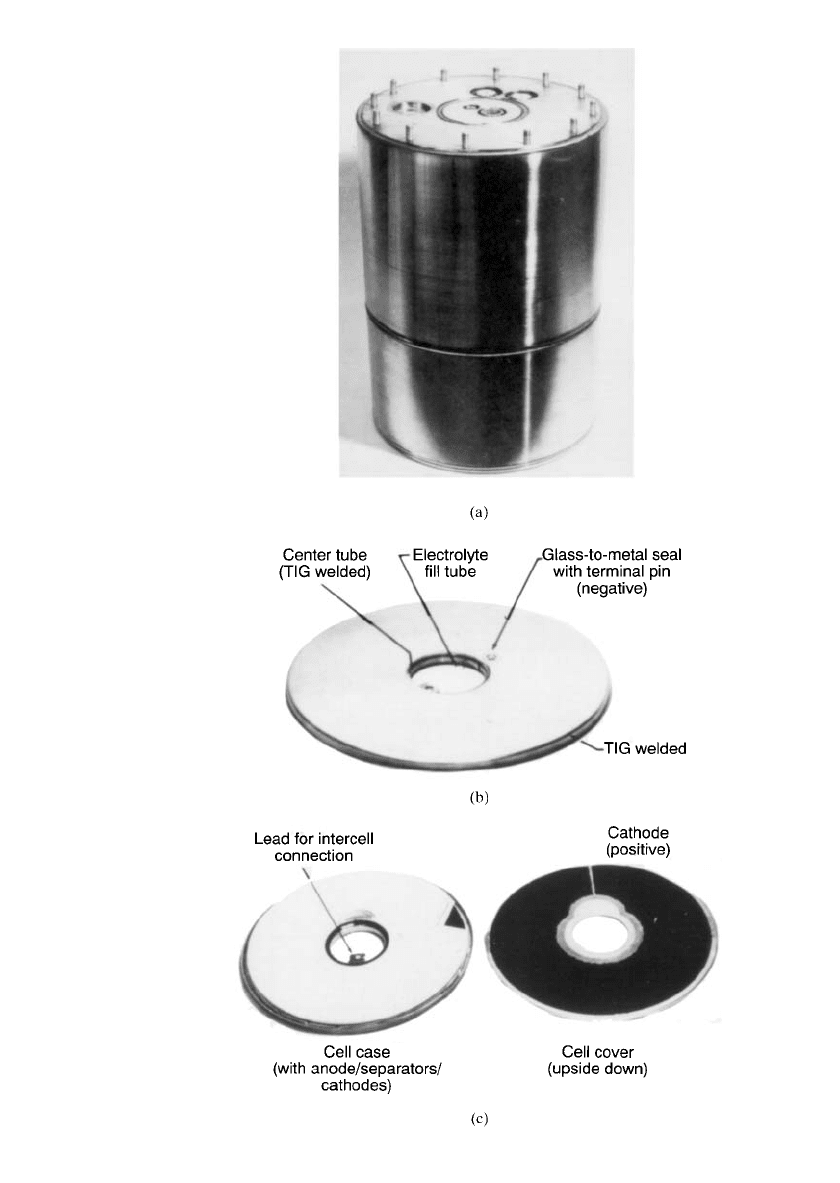
20.10 CHAPTER TWENTY
FIGURE 20.8 High-power reserve battery BA-6511 / SLQ. (a) Li / SOCl
2
reserve battery. (b) High-power cells. (c) High-power cell case and elec-
trode assembly. (Courtesy of Alliant Techsystems, Inc.)

AMBIENT-TEMPERATURE LITHIUM ANODE RESERVE BATTERIES 20.11
ocean buoys.
12
The reserve battery was selected for this application to eliminate the problems
of self-discharge and passivation associated with extended stand of an active battery, but also
for safety as the electrolyte is stored separately from the battery until activation.
The battery weighs about 145 lb and is contained in a package that is 29.2 cm in diameter
and 43.2 cm long. The battery contains 21 cells; 18 cells compose a 56-V section, delivering
4 kW, and rated at 65 Ah; 3 cells are in a 10-V section, delivering 7 A, and rated at 57 Ah.
The electrolyte is stored in a reservoir and is distributed to the 21 cells via a unique mani-
folding system. Activation is initiated by an explosive squib, and a stored energy system
within the reservoir provides the motive power. The cell design used for this battery (Fig.
20.8b) is a circular wafer with a hole through the center to provide a channel for electrical
and tubing connections. The two types of cells used in the battery are physically similar,
differing only in height and capacity as a result of one less set of electrodes. The cells used
in the high-voltage, high-rate section contain five anodes and six cathodes. Anodes are single-
sided with lithium pressed onto expanded nickel grids. The cathode is cut from coated stock
of Teflonated
carbon on a nickel screen, as shown in Fig. 20.8c. Nonwoven glass separators
are used. The specifications for the two cells are listed in Table 20.2.
TABLE 20.2 Characteristics of Li/ SOCl
2
Reserve Cells Model G3070A2
Low-rate reserve cell High-rate reserve cell
Performance
Open-circuit voltage 3.67 V 3.67 V
(activated)
Voltage under load 3.40 V, 7 A at 20
⬚C 3.10 V, 72 A at 20⬚C
Rated capacity 57 Ah at 7 A to 65 Ah at 72 A to
2.67 V at 20
⬚C 2.63 V at 20⬚C
Physical characteristics:
Max diameter, OD 28.5 cm 28.5 cm
Max diameter, ID 6.7 cm 6.7 cm
Max height 0.89 cm 1.04 cm
Cell weight with electrolyte 1310 g 1485 g
Case material Stainless steel Stainless steel
Source: Alliant Techsystems, Inc.
Another more recent example of this reserve design using a pre-charged Li
x
CoO
2
(0.5 ⱕ
x ⬍ 1) chemistry
13
is shown in Fig. 20.9. This reserve battery consists of three hermetically-
welded cell cases with a central reservoir enclosed in a stainless steel battery housing. Such
a battery was developed to power the Hand-Emplaced Wide Area Munitions (HWAM).
Figure 20.10 shows another multicell battery designed for light weight missile applica-
tions.
14
Based on the Li /oxyhalide technology, it used advanced thin electrode technology
that has high energy utilization and low electrical impedance. A composite separator was
also used that combines high electrolyte absorption and mechanical integrity. This type of
high power design sees applications such as the Theater High Altitude Area Defense
(THAAD) in a Kill Vehicle for the Ground Based Interceptor (GBI) program. Other advan-
tages of this light weight, high power battery are: (1) reduction in battery weight over the
thermal or silver zinc system; (2) specific energy greater than 250 Wh/kg; (3) gain in weight
advantage as the mission time increases or as the energy to power ratio increases; (4) high
power delivery even after 10 years of storage at temperature below
⫺32⬚C; and (5) low
operating temperature allowing locations near heat sensitive electronics.
