Linden D., Reddy T.B. (eds.) Handbook of batteries
Подождите немного. Документ загружается.

19.2 CHAPTER NINETEEN
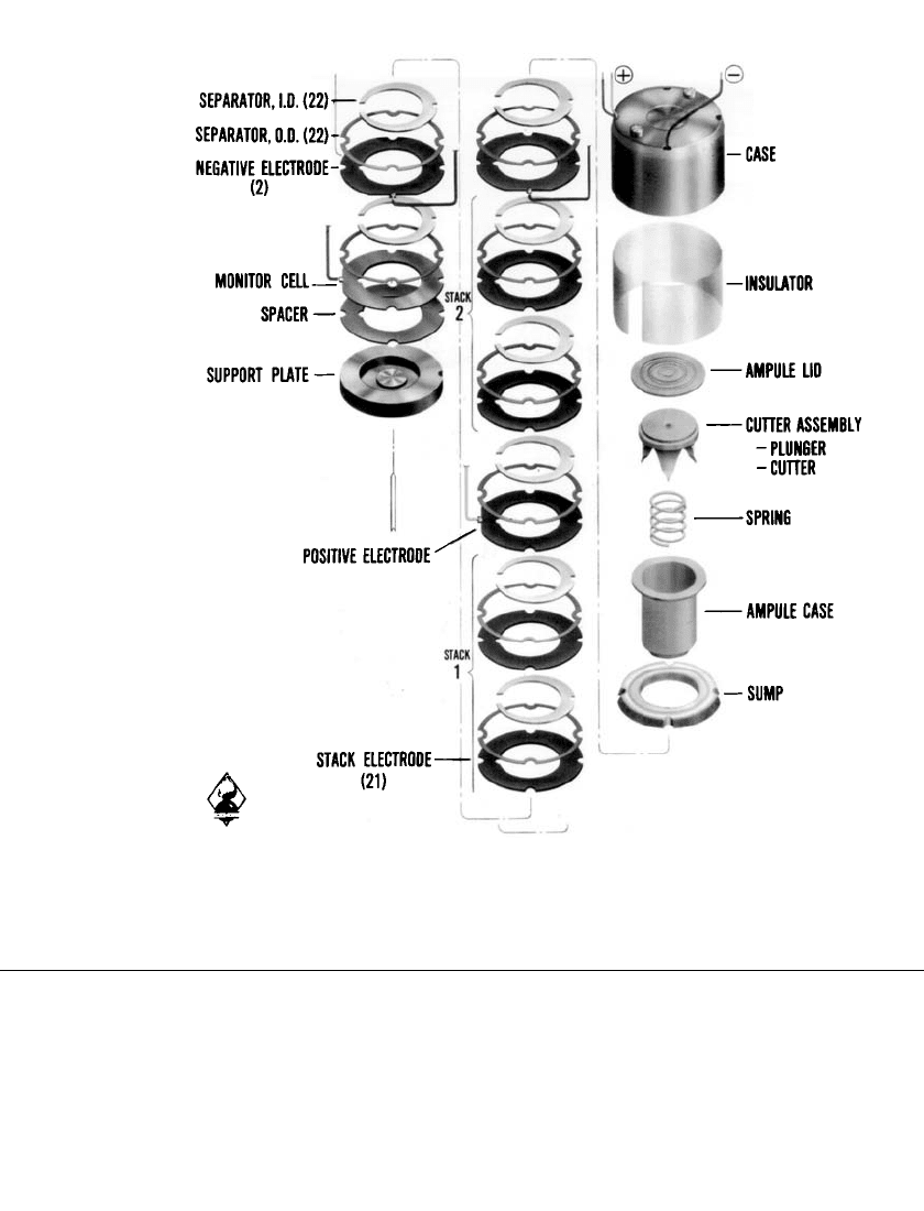
FIGURE 19.2 Component parts of lead/ fluoboric acid / lead dioxide multicell reserve bat-
tery, PS 416 power supply. (Courtesy of U.S. Department of the Army.)
19.2 CHEMISTRY
The chemistry most commonly employed in spin-dependent liquid-electrolyte reserve bat-
teries has been the lead /fluoboric acid/lead dioxide cell represented by the following sim-
plified reaction:
Pb
⫹ PbO ⫹ 4HBF → 2Pb(BF ) ⫹ 2H O
24 422
Fluoboric acid, rather than the more common sulfuric acid electrolyte, is used for these
applications because it performs better at the very low temperatures required for these mil-
itary applications. This low-temperature performance is due in part to the absence of insol-
uble reaction products as the reserve battery discharges.

SPIN-DEPENDENT RESERVE BATTERIES 19.3
More recently, spin-dependent liquid-electrolyte reserve batteries employing lithium an-
odes have been developed. The most promising system is that in which thionyl chloride
serves in the dual role of electrolyte carrier and active cathodic depolarizer (see Chap. 20).
The accepted cell reaction for this system is
4Li
⫹ 2SOCl → 4LiCl ⫹ S ⫹ SO .
22
At one time, the zinc /potassium hydroxide/silver oxide system was also employed in spin-
dependent reserve batteries. More frequently, this reserve system has been used in nonspin
applications, such as missiles, where the electrolyte is driven into place by a gas generator
or other activation method (Chap. 18). This system is again finding favor in some applications
where the potential hazards of lithium-based systems can create safety problems. The chem-
istry of the zinc/ silver oxide couple can be represented by either of two reactions, depending
on the oxidation state of the silver oxide:
2AgO
⫹ Zn → Ag O ⫹ ZnO
2
Ag O ⫹ Zn → 2Ag ⫹ ZnO
2
Within the past five years, thermal batteries that can operate at high spin rates (300 rps)
have been developed and successfully demonstrated. These batteries have been based on the
now standard lithium (alloy)/iron disulfide couple employed in most thermal batteries (see
Chap. 21 for a detailed discussion of these chemistries).
19.3 DESIGN CONSIDERATIONS
19.3.1 Electrode-Stack Arrangement
The electrode stack may be arranged in two ways. One favors a high-voltage output, and
the other a high-current output. The former generally uses bipolar electrodes; that is, elec-
trodes wherein anodic and cathodic materials, respectively, are applied to the opposite sides
of a metal substrate. Such bipolar electrode plates are stacked in a pile or series configuration,
making automatic contact from one cell to the next. The voltage output of such a stack is
the sum of all the cells. In the high-current configuration, electrode plates coated with anodic
material on both sides of the substrate are stacked alternately with plates coated with cathodic
material on both sides. All anodic plates are connected electrically in parallel through tabs.
All cathodic plates are similarly connected. The two electrical connections constitute the
effective terminals of the battery. This type of parallel stack is, in effect, a single electro-
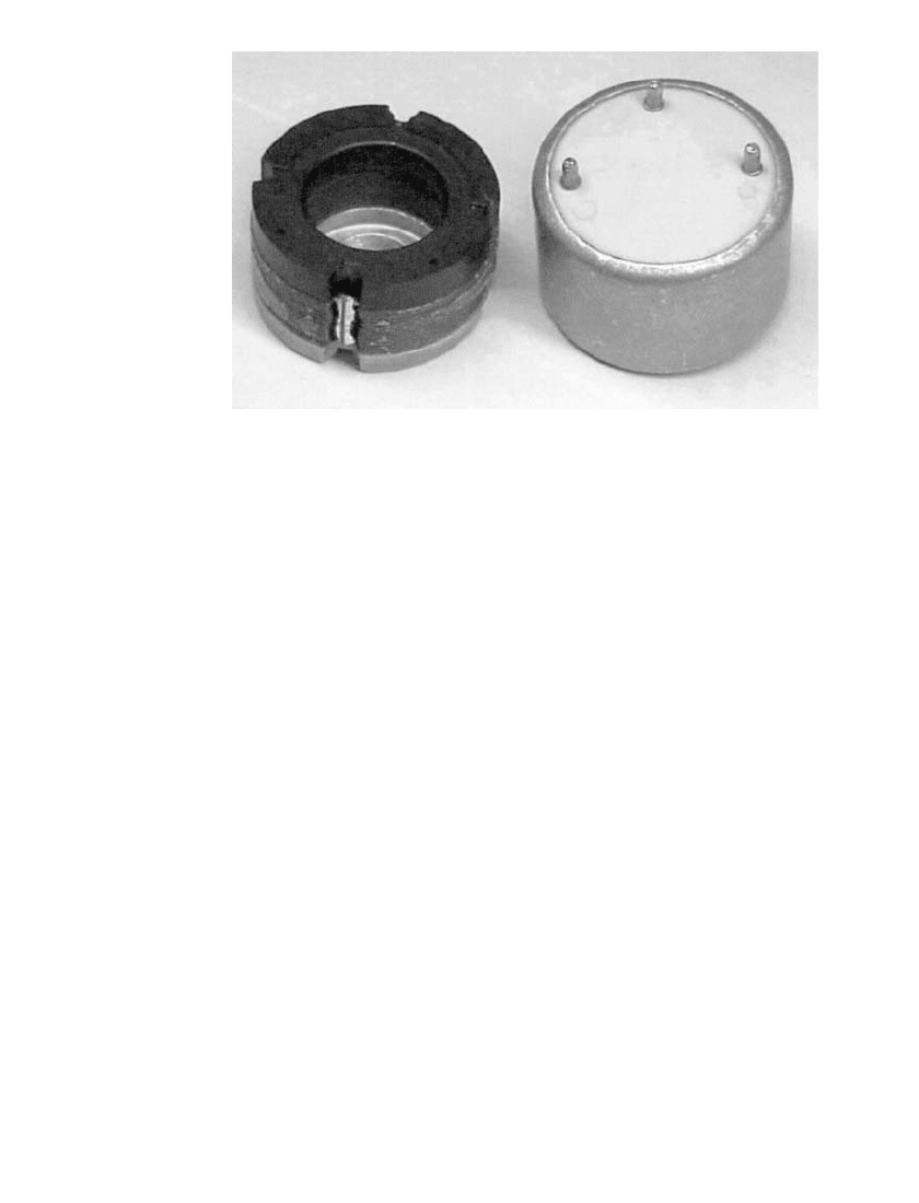
chemical cell with a larger electrode area (Fig. 19.3). Where required by the application,
multiples of series stacks can be connected in parallel, thereby yielding both high-voltage
and high-current outputs.
19.4 CHAPTER NINETEEN
FIGURE 19.3 Electrode stack and case of lead / fluoboric acid / lead dioxide par-
allel-construction (single cell) battery. (Courtesy of U.S. Department of the Army.)
19.3.2 Electrolyte Volume Optimization
The electrolyte capacity of the ampoule must be matched to the composite volume of all
the cells in the battery. A parallel construction battery is reasonably tolerant of electrolyte
flooding or starvation since it is a single cell. A series configuration, however, can tolerate
no flooding since that condition produces intercell short circuits in the electrolyte fill channel
or manifold. The opposite condition, that is, insufficient electrolyte, may leave one or more
cells empty and therefore fail to provide continuity throughout the cell stack.
Since temperature extremes have a greater effect on the expansion and contraction of the
liquid electrolyte than on the volume of the cells, an electrolyte volume that ensures that the
cells will be reasonably full at low temperatures usually leads to an excess of electrolyte at
higher temperatures. This excess must be accommodated in the design of the battery by the
use of a ‘‘sump.’’ In some short-life batteries, a match is established at high temperature
with the recognition that cells will be less than full at lower temperatures. To ensure that
some electrolyte enters each cell (so that continuity can be maintained), leveling holes may
be provided from cell to cell. Though kept very small to reduce the effect of inevitable
intercell short circuits, these holes do dissipate some of the capacity of the battery.
19.3.3 Cell Sealing
Since the individual cells of a spin-dependent liquid-electrolyte reserve battery are generally
annular in shape and are filled by centrifugal force, the periphery of the cell must be sealed
to keep electrolyte from leaking out. This sealing is typically accomplished by a plastic
barrier formed around the outside of the electrode-spacer stack. For lead/ fluoboric acid /lead
dioxide batteries, this barrier is formed by fish paper (a dense, impervious paper) coated
with polyethylene that melts at a relatively low temperature (similar to that used on milk
cartons). Cell spacers are punched from the coated fish paper and placed between the elec-
trodes. The stack is then clamped together and heated in an oven at a temperature sufficient
to fuse the polyethylene, which then acts as an adhesive and sealer between the electrodes.

SPIN-DEPENDENT RESERVE BATTERIES 19.5
19.3.4 Ampoules
Early designs of liquid-electrolyte reserve batteries used glass ampoules to house the elec-
trolyte, and in fact, some modern batteries still use such ampoules. These ampoules are
generally smashed by the acceleration force of gunfire or by the explosive output of a primer
or squib. Although these forces are ample, there is also a tendency for rough handling or a
drop on a hard surface to cause inadvertent glass ampoule breakage. This would destroy the
battery due to the premature leakage of electrolyte into the cells.
A major advance in battery ruggedness resulted from the design of metal, usually copper,
ampoules with internal cutting mechanisms. One version employs a cutter that is activated
by a combination of spin and acceleration (Fig. 19.4), both provided by the act of gunfire.
Another version relies on a dashpot cutter mechanism (Figs. 19.1 and 19.2). This mechanism
requires a sustained acceleration (several milliseconds experienced in gunfire), but will not
function when subjected to the much shorter (a portion of a millisecond) shock pulse re-
sulting from being dropped on a hard surface. The use of these ‘‘intelligent’’ ampoules,
which are capable of discriminating between the forces of gunfire and those of rough han-
dling, has resulted in a substantial improvement in battery reliability and safety.
FIGURE 19.4 Three-bladed cutter for copper ampoule re-
quiring spin and acceleration for activation. (Courtesy of U.S.
Department of the Army.)
19.3.5 Safety in Lithium-Based Batteries
For at least the past ten years, reserve single-cell batteries that use various lithium-based
electrochemistries have been employed in a number of fuzing applications. These cells are
normally constructed with an anode-separator-cathode assembly spirally wound around a
centrally located glass electrolyte ampoule. The electrolyte ampoule is normally broken upon
gunfire or as the result of the bottom of the cell case being struck with a squib- or spring-
driven device. Since these are single-cell devices, there is no chance for intercell short-
circuiting and subsequent safety problems.
However, in multicell pile configuration reserve batteries, there is a considerable chance
for intercell short-circuiting in the common electrolyte manifold. This intercell shortcircuiting
not only dissipates the capacity of the cells, but it can also allow for dendritic growth, which
can lead to electronic short-circuiting of the cells with catastrophic results. Experience has
shown that such dendritic growth can be minimized or eliminated if all interior metallic
surfaces of the battery have a nonconductive (usually Teflon-based) coating.

19.6 CHAPTER NINETEEN
19.4 PERFORMANCE CHARACTERISTICS
19.4.1 General
Energy and Power Density. Liquid-electrolyte reserve batteries are not normally rated in
terms of energy or power per unit weight or per unit volume. Because of the need to provide
double the volume for the electrolyte (one volume in an ampoule, the other in the cells
themselves), such batteries are not highly space efficient. Space is also consumed by the
ampoule-opening mechanism and the cell-sealing material. Furthermore, the cell area is
sometimes not exposed to the electrolyte because of the spin eccentricity of the projectile,
which houses the battery. Finally, such batteries are generally designed for short-lifetime
applications, such as the flight time of an artillery projectile (approximately 3 min).
Operating Temperature Limits. Like most other batteries, the performance of liquid-
electrolyte reserve batteries is affected by temperature. Military applications frequently de-
mand battery operations at all temperatures between
⫺40 and 60⬚C, with storage limits of
⫺55 to 70⬚C. These requirements are routinely met by the lead /fluoboric acid/lead dioxide
systems and, with some difficulty at the low-temperature end, by the lithium/ thionyl chloride
and zinc/potassium hydroxide/silver oxide systems. Provision is occasionally made to warm
the electrolyte prior to the activation of the two latter systems.
Voltage Regulation. Since the voltage sustained by a liquid-electrolyte reserve battery at
low temperatures and under heavy electric loading is much lower than that which it delivers
at high temperatures, a serious problem of voltage regulation frequently results. In some
situations, the ratio of high- to low-temperature voltage may be as much as 2:1. This problem
may be avoided by the use of thermal batteries (Chap. 21), which provide their own pyro-
technically induced operating temperature, irrespective of the ambient temperature. Until
recently, thermal batteries were extremely ineffective at high spin rates, but progress has
been made in this field and thermal batteries capable of withstanding spin rates of 300 rps
are now available.
Shelf Life. The shelf life of liquid-electrolyte reserve batteries is highly dependent on the
storage temperature, with high temperatures being the more deleterious. Zinc /silver oxide
cells are probably the most vulnerable of the generally used systems because of the reduction
of silver oxide and the passivation of zinc. Ten-year storage life is probably the best that
can be expected unless the battery is substantially overdesigned. Lead/fluorboric acid/ lead
dioxide batteries also degrade with time, in both the loss of capacity and the lengthening of
activation time. However, if objectionable organic materials are avoided in battery construc-
tion and the battery is designed with some safety factors, 20 to 25 years of shelf life may
be realized. Lithium/thionyl chloride reserve systems are still too new to have a documented
storage history; however, a long storage capability is projected for a properly (dry) built and
sealed battery.
Linear and Angular Acceleration Limits. Since spin-activated batteries are normally ex-
pected to be used in environments where guns are used, they must be built to withstand the
forces of gunfire. With the development of the ampoules and the construction methods de-
scribed, such batteries can withstand linear acceleration to the 20,000 to 30,000-g level and
spin rates as great as 30,000 rpm. The sizes intended for small-caliber (20 to 40-mm) pro-
jectiles will withstand linear g levels 2 to 5 times that high.
As an assist in withstanding these forces, the battery assembly is sometimes encapsulated
in a supporting plastic. A popular design involved a molded plastic cup to house the stack
and ampoule assembly, which was locked in place with an epoxy resin. More recently, the
stack and ampoule assembly has been encapsulated in situ in a RIM (reaction impingement
molding) process using a high-impact polyurethane foam, a process that allows demolding
in just minutes. These two types of support are shown in Fig. 19.5.

SPIN-DEPENDENT RESERVE BATTERIES 19.7
FIGURE 19.5 Stack and ampoule assembly of a lead / fluoboric acid /lead
dioxide reserve battery supported by potting in epoxy in a molded case (left)
and by in situ molding using a reaction impingement molded polyurethane
foam (right). (Courtesy of U.S. Department of the Army.)
Activation Time. The time from initiation of the battery to the point at which it delivers
and sustains a requisite level of voltage across a specified electric load is defined as the
activation time. For a spin-dependent liquid-electrolyte reserve battery, this time would in-
clude the times for ampoule opening, electrolyte distribution, clearing of electrolyte short
circuits in the filling manifold, depassivation of electrodes, and elimination of any form of
polarization. Activation times are usually longest at low temperatures, where increased vis-
cosity of the electrolyte and decreased ion mobility are most significant.
The application normally establishes the maximum allowable activation time, and reserve
batteries are frequently designed to reach 75 or 80% of their peak voltage within this required
time. A typical application requiring a very short activation time, perhaps less than 100 ms,
would be a time fuze for an artillery projectile. Battery power is required to start the timer.
Hence a stretch-out or uncertainty of time to reach timer voltage could result in a serious
timing error, with a corresponding ineffectiveness of gunfire. In some cases, safety can be
adversely affected by a timing error. In less critical situations, 0.5 to 1.0 s is allowed for
activation.
19.4.2 Performance of Specific Electrochemical Systems
The physical and electrical characteristics of several typical spin-dependent reserve batteries
are presented in Table 19.1.
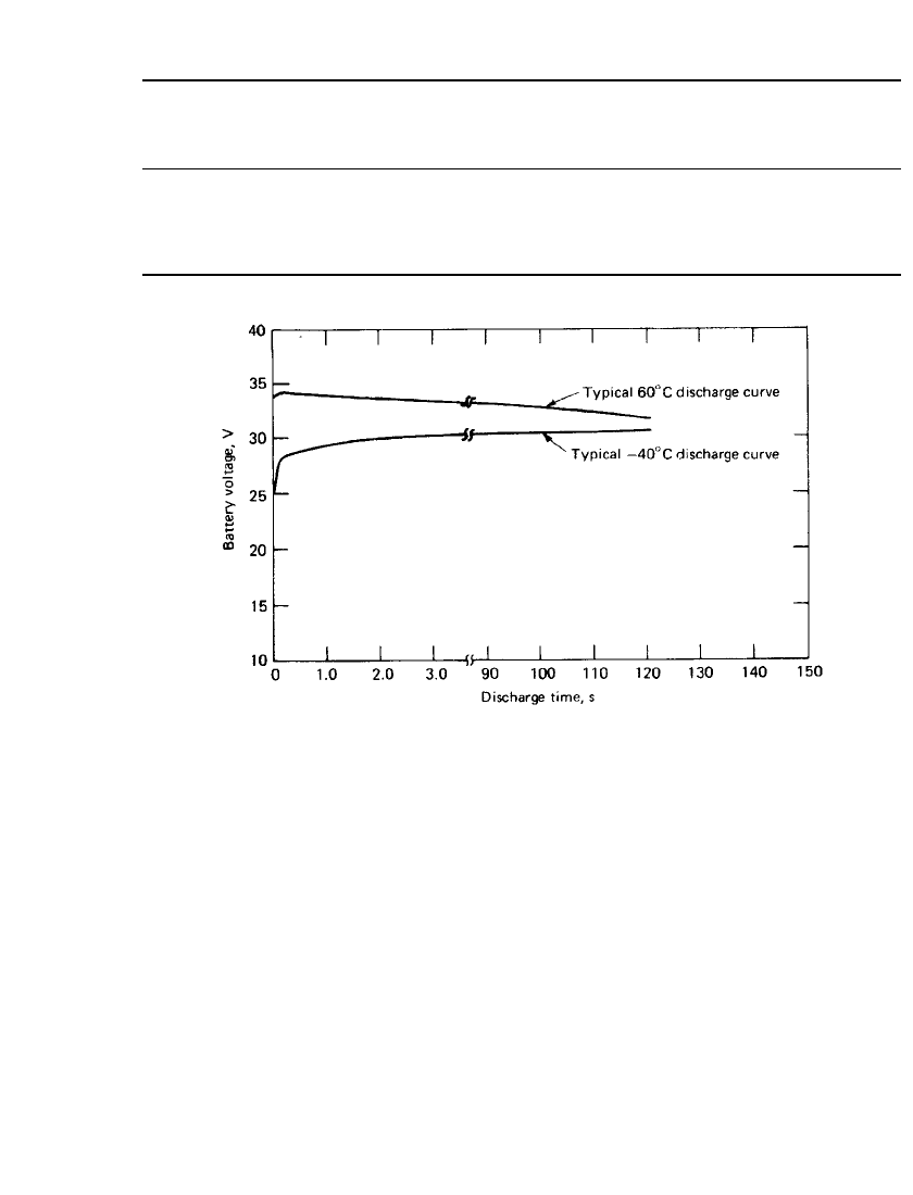
Lead/ Fluoboric Acid/ Lead Dioxide Battery. Discharge curves for a typical lead/fluoboric
acid/ lead dioxide liquid-electrolyte reserve battery employed to power the proximity fuze of
an artillery shell are given in Fig. 19.6. The slight rise in the low-temperature curve is due
to its gradual rise in temperature in a room-temperature spinning tester. Similarly, the high-
temperature curve is falling faster than it would in a true isothermal situation.
19.8 CHAPTER NINETEEN
TABLE 19.1 Typical Spin-Dependent Reserve Batteries
Reference
Electro-chemical
system
Height,
cm
Diameter,
cm
Weight,
g
Nominal
voltage,
V
Nominal
capacity,
Wh
Fig. 19.1 Pb/ HBF
4
/PbO
2
4.1 5.7 280 35 0.5
Fig. 19.3 Pb/ HBF
4
/PbO
2
2.5 3.8 75 1.5 0.05
Fig. 19.8 Li/ SOCl
2
1.67 3.8 70 12 0.37
Zn/ KOH/AgO 1.3 5.1 80 1.4 0.65
FIGURE 19.6 Discharge curves of a spinning lead / fluoboric acid / lead dioxide
series-configuration reserve battery. Current density: 100 mA / cm
2
.(Courtesy of U.S.
Department of the Army.)
Lithium/ Thionyl Chloride Battery. Until recently, spin-dependent batteries were expected
to function for short periods of time and only under sustained spin (necessary to keep the
electrolyte within the cells). New applications have arisen that require a battery capable of
withstanding artillery fire and spinning for a short time followed by some substantial oper-
ating time in a nonspin mode. Such applications include artillery delivery of mines or com-
munication jammers intended to function after impact with the ground, or projectiles and
submunitions that are operative while being slowed down by parachute.
The lithium-based liquid-electrolyte reserve battery holds promise of fulfilling this diffi-
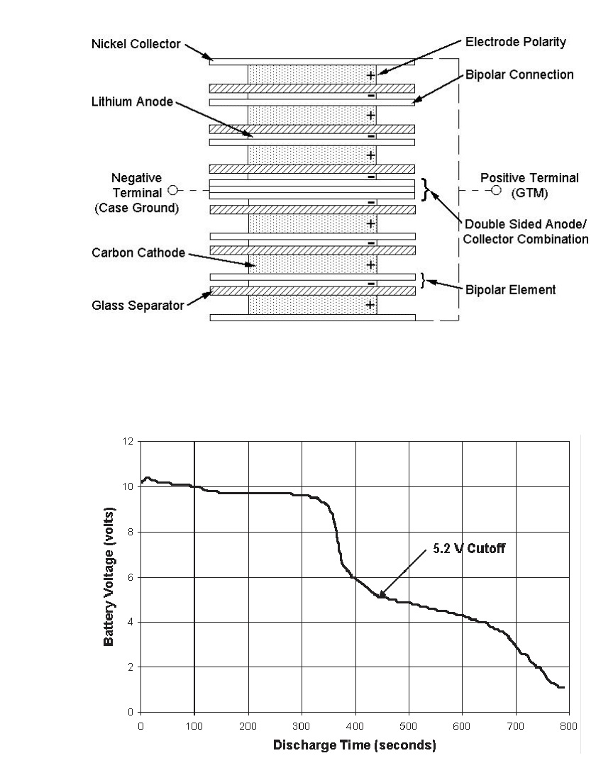
cult combination of requirements. A typical cell, as illustrated in Fig. 19.7, incorporates an
absorbing separator such as a nonwoven glass mat between the electrodes, and a long, high-
resistance electrolyte filling path. After cell filling under spin, the absorbing material causes
the electrolyte to be retracted away from the manifold and retained within the cell after
cessation of spin. These design features, coupled with the long wet-stand capability of the
lithium/ thionyl chloride system, have paved the way for reserve batteries in applications that
previously had to depend on the use of active batteries with relatively shorter storage ca-
pability. A discharge curve for a multicell, liquid-electrolyte reserve battery is given in Fig.
19.8 (also see Chap. 20).
SPIN-DEPENDENT RESERVE BATTERIES 19.9
FIGURE 19.7 Quarter cross-sectional view of the cell stack of a lithium/ thionyl chloride reserve battery.
(Courtesy of Alliant Power Sources Company.)
FIGURE 19.8 Discharge curve of a spinning (45 rps) lithium/ thionyl chloride reserve battery at 25⬚
C. Current density: 35 mA /cm
2
.(Courtesy of Alliant Power Sources Company.)

19.10 CHAPTER NINETEEN
Spin-Capable Thermal Batteries. Because of their lower susceptibility to temperature ex-
tremes and known superior shelf life (without degradation), thermal batteries have been
desired as an alternative to liquid-electrolyte reserve batteries for some time. The primary
failure mode for thermal batteries in a high-spin environment had always been intercell short-
circuiting at the cell stack edges due to the leakage of molten conductive materials at battery
operating temperatures. New construction techniques, new electrochemistries that allow for
higher electrolyte binder contents, and lithium alloy anodes that prevent migration of the
anode material have made spin-capable thermal batteries practical.
BIBLIOGRAPHY
Benderly, A. A.: ‘‘Power for Ordnance Fuzing,’’ National Defense, Mar.–Apr. 1974.
Biggar, A. M.: ‘‘Reserve Battery Requiring Two Simultaneous Forces for Activation,’’ Proc. 24th Annual
Power Sources Symp., Electrochemical Society, Pennington, NJ, pp. 39–41, 1970.
Biggar, A. M., R. C. Proestel, and W. H. Steuernagel: ‘‘A 48-Hour Reserve Power Supply for a Scat-
terable Mine,’’ Proc. 26th Annual Power Sources Symp., Electrochemical Society, Pennington, NJ, pp.
126–129, 1974.
Doddapaneni, H., D. L. Chua, and J. Nelson: ‘‘Development of a Spin Activated, High Rate, Li / SOCl
2
Bipolar Reserve Battery,’’ Proc. 30th Annual Power Sources Symp., Electrochemical Society, Penning-
ton, NJ, pp. 201–204, 1982.
Krieger, F. C.: ‘‘Miniaturized Thermal Reserve Battery,’’ Proc. 38th Annual Power Sources Conference,
U.S. Army CECOM / ARL, Cherry Hill, NJ, pp. 231–234, 1998.
Morganstein, M., and A. B. Goldberg: ‘‘Reaction Impingement Molding (RIM) Encapsulation of a Fuze
Power Supply,’’ Proc. of the 4th International SAMPE Electronics Conference, Society for the Ad-
vancement of Material and Process Engineering, Covina, CA, pp. 753–764, 1990.
Schisselbauer, P. F., and D. P. Roller, ‘‘Reserve g-Activated, Li/ SOCl
2
Primary Battery for Artillery
Applications,’’ Proc. 37th Annual Power Sources Conference, U.S. Army CECOM /ARL, Cherry Hill,
NJ, pp. 357–360, 1996.
Turrill, F. G., and W. C. Kirchberger: ‘‘A One-Dollar Power Supply for Proximity Fuzes,’’ Proc. 24th
Annual Power Sources Symp., Electrochemical Society, Pennington, NJ, pp. 36–39, 1970.
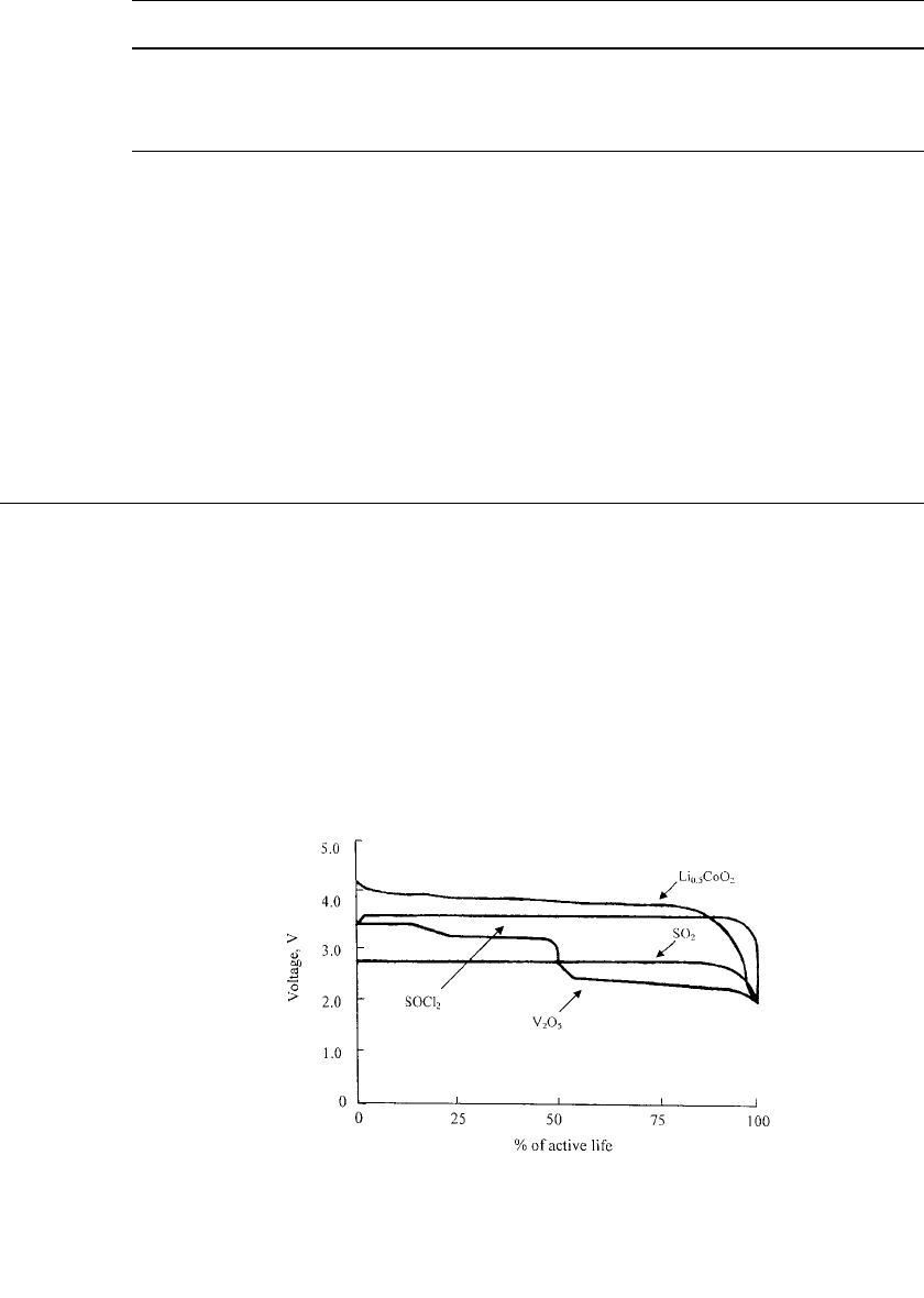
20.1
FIGURE 20.1 Performance comparison of lithium anode primary
systems at 20⬚C. Thionyl chloride (SOCl
2
)—3.6 V; vanadium pent-
oxide (V
2
O
5
)—3.4 V; sulfur dioxide (SO
2
)—2.9 V; precharged lith-
iated cobalt oxide (Li
x
CoO
2
, x ⫽ 0.4 ⫺ 0.5) ⫺ 4.0 V.
CHAPTER 20
AMBIENT-TEMPERATURE LITHIUM
ANODE RESERVE BATTERIES
David L. Chua, William J. Eppley, and Robert J. Horning
20.1 GENERAL CHARACTERISTICS
The use of lithium metal as an anode in reserve batteries provides a significant energy
advantage over the traditional reserve batteries because of the high potential and low equiv-
alent weight (3.86 Ah/ g) of lithium. A lithium reserve battery can operate at a voltage close
to twice that of the conventional aqueous types. Due to the reactivity of lithium in aqueous
electrolytes, with the exception of the special lithium-water and lithium-air batteries (see
Sec. 38.6), lithium batteries must use a nonaqueous electrolyte with which lithium is non-
reactive.
The various ambient-temperature active (non-reserve) lithium batteries are covered in
Chap. 14. Of these systems, the ones demonstrating the higher energy densities and rate
capabilities are Li/ SO
2
, Li/V
2
O
5
, Li /SOCl
2
, and Li/ Li
x
CoO
2
. The discharge characteristics
of these batteries are shown in Fig. 20.1. These are the electrochemical systems that are
predominately employed in the reserve-type configurations.
