Linden D., Reddy T.B. (eds.) Handbook of batteries
Подождите немного. Документ загружается.

LITHIUM-ION BATTERIES 35.29
35.2.6 Separator Materials
Li-ion cells use thin (10 to 30
m), microporous films to electrically isolate the positive and
negative electrodes. To date, all commercially available liquid electrolyte cells use micro-
porous polyolefin materials as they provide excellent mechanical properties, chemical sta-
bility and acceptable cost. Nonwoven materials have also been developed but have not been
widely accepted, in part due to the difficulty in fabricating thin materials with uniform, high
strength.
81
Requirements for Li-ion separators include:
•
High machine direction strength to permit automated winding
•
Does not yield or shrink in width
•
Resistant to puncture by electrode materials
•
Effective pore size less than 1
m
•
Easily wetted by electrolyte
•
Compatible and stable in contact with electrolyte and electrode materials
Microporous polyolefin materials in current use are made of polyethylene, polypropylene
or laminates of polyethylene and polypropylene. Also available are surfactant coated mate-
rials, designed to offer improved wetting by the electrolyte. These materials are fabricated
by either a dry, extrusion type process or a wet, solvent based process.
82
The properties of
commercial materials, including pore dimensions, porosity, and permeability, have been re-
ported.
83
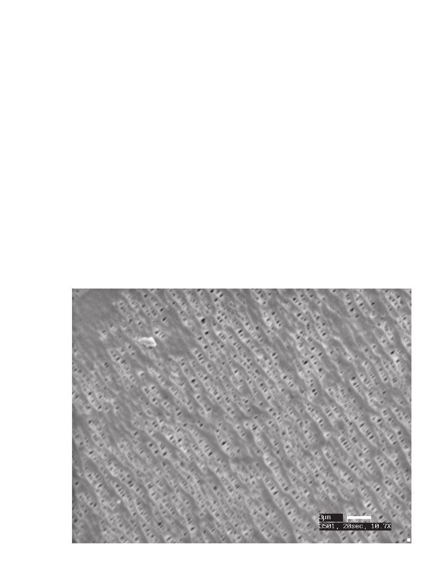
Commercial materials offer pore size of 0.03
m to 0.1
m, and 30 to 50% porosity,
as illustrated by the SEM micrograph of a commercial material in Fig. 35.28.
FIGURE 35.28 SEM micrograph of Celgard 3501 separator. (Courtesy of Yardney Technical Products,
Inc.)
35.30 CHAPTER THIRTY-FIVE
The low melting point of polyethylene (PE) materials enables their use as a thermal fuse.
As the temperature approaches the melting point of the polymer, 135
⬚C for polyethylene and
165
⬚C for polypropylene (PPE), porosity is lost.
84
Tri-layer materials (PPE/PE/PPE) have
been developed where a polypropylene layer is designed to maintain the integrity of the
film, while the low melting point of polyethylene layers is intended to shutdown the cell if
an over-temperature condition is reached.
35.2.7 Additives
To further improve battery performance, electrolyte additives have been developed. Some,
such as BF
3
,
85
and related complexes, are designed to passivate the surface of electrode
materials thereby reducing their propensity to degrade. Others, such as hexamethyldisilazane
(HMDS), have been used to reduce interfacial resistance,
86
and react with and immobilize
water and HF, thus improving cell performance:
87
(CH ) SiN(H)Si(CH ) ⫹ HO→ (CH ) SiOSi(CH ) ⫹ NH
33 33 2 33 33 3
NH ⫹ HF → NH F
34
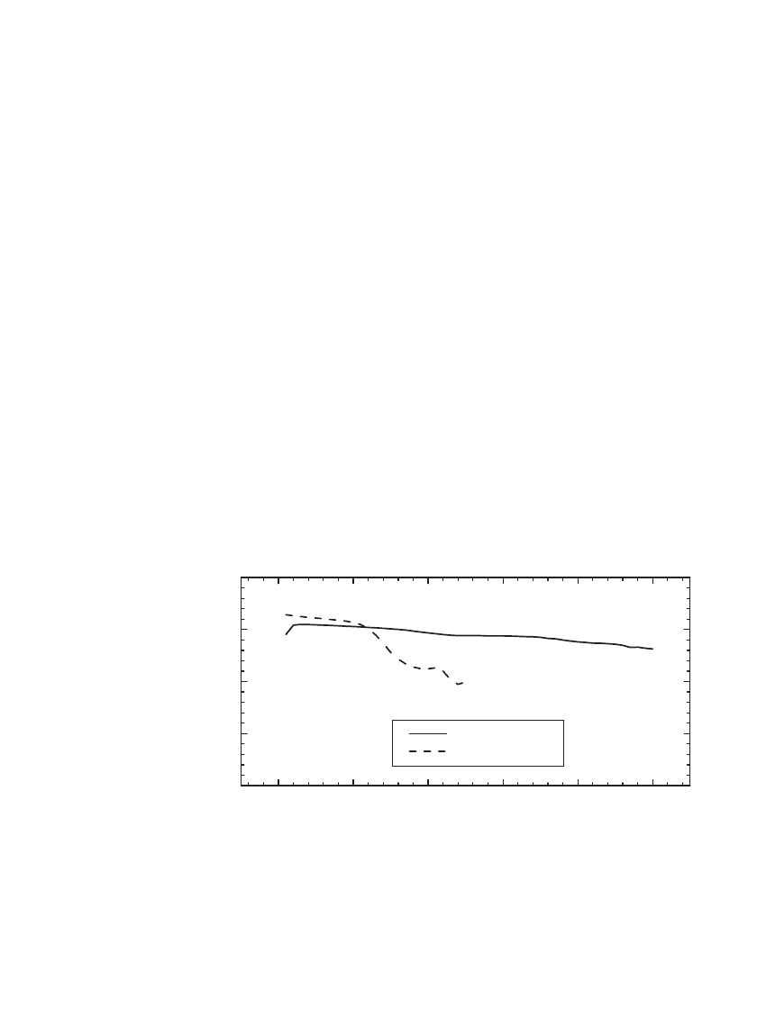
To illustrate the utility of one such additive, Fig. 35.29 shows the specific capacity of a
Li/ LiMn
2
O
4
battery cycled at 55⬚C using an electrolyte with and without HMDS additive.
As shown, the cell with the HMDS additive provided lower capacity fade in this case, as
the additive removed the water and HF impurities that contribute to the degradation of the
electrode materials.
0 1020304050
60
80
100
120
140
Specific Capacity
Cycle
With HMDS
Without HMDS
FIGURE 35.29 The specific capacity of C / LiMn
2
O
4
battery when cycled at 55⬚Cin
an electrolyte with and without HMDS additive. Cycled at C/ 2 rate, 4.2 V to 3.5 V.
(Courtesy of Carus Chemical.)

LITHIUM-ION BATTERIES 35.31
35.3 CONSTRUCTION OF CYLINDRICAL AND PRISMATIC Li-ION
CELLS AND BATTERIES
Cylindrical and prismatic Li-ion batteries have been developed. Wound designs are typical
in small cells (
⬍4 Ah); however in large cell designs, prismatic configurations with flat plate
construction are more common. For prismatic Li-ion batteries two cell design types are
practiced, flat mandrel wound pseudo-prismatic designs and flat-plate true prismatic designs.
Since Li-ion cells are fabricated in the discharged state, they must be charged before use.
35.3.1 Construction of Wound Li-ion Cells
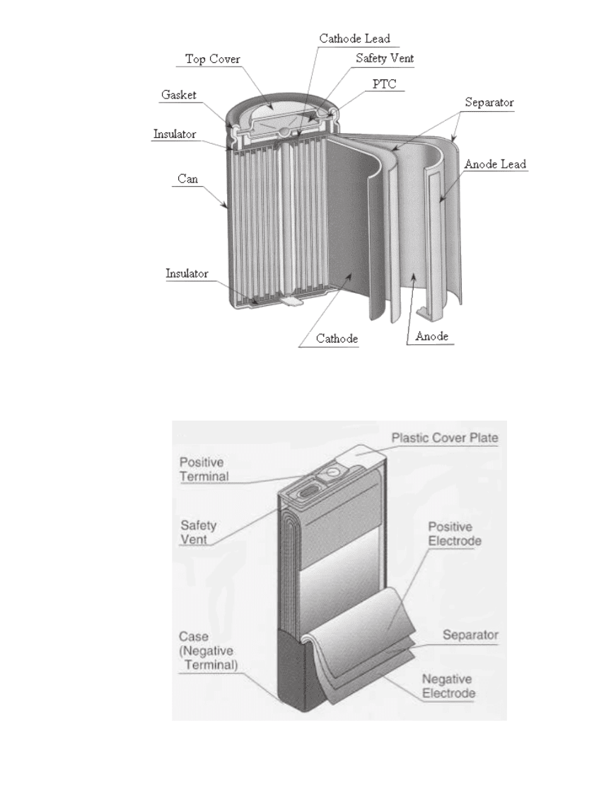
The construction of a cylindrical wound Li-ion cell is illustrated in Fig. 35.30. The fabrication
of wound prismatic cells is similar to cylindrical versions except that a flat mandrel is used
instead of a cylindrical mandrel. A schematic diagram of a wound prismatic cell is shown
in Fig. 35.31. The construction consists of a positive and negative electrode separated by a
16
mto25
m thick microporous polyethylene or polypropylene separator. Positive elec-
trodes consist of 10
mto25
m Al foil coated with the active material to a total thickness
typically
⬃180
m. Negative electrodes are typically 10
mto20
m Cu foil coated with
a carbonaceous active material to a total thickness
⬃200
m. The thin coatings and separator
are required because of the low conductivity of non-aqueous electrolytes,
⬃10 mS /cm,
88
and
slow Li
⫹
diffusion in the positive and negative electrode materials, about ⬃10
⫺
10
m
2
s
⫺
1
.
Typically a single tab at the end of the wind is used to connect the current collectors to their
respective terminals. The case, commonly used as the negative terminal, is typically Ni-
plated steel. When used as the positive terminal, the case is typically aluminum. Most com-
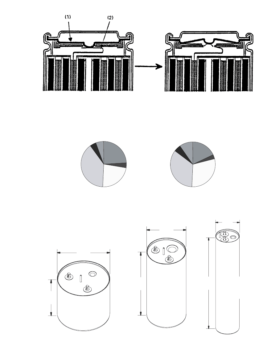
mercially available cells utilize a header that incorporates disconnect devices, activated by
pressure or temperature, such as a PTC device, and a safety vent. One design is illustrated
in Fig. 35.32. These devices can limit cell performance at high rates, i.e. in a typical 18650
cell, 12 A discharge results in disconnect after 20 seconds once the temperature of the
disconnect device reaches 70
⬚C due to resistive heating. The header-can seal is typically
formed through a crimp.
In a typical 18650 cell, the positive current collector is coated on both sides with 12 g
of LiCoO
2
resulting in an electrode thickness of ⬃7.0 mil. Typically 6.5 g of carbon is used
on the negative electrode and the positive to negative ratio is such that the carbon negative
is utilized at a maximum of 270 mAh /g, 10% less than the capacity typical for MCMB
carbon and 100 mAh/g less than the theoretical capacity of carbon, (372 mAh/g).
89
The
mass distribution for the components in two 18650 products is illustrated in Fig. 35.33.
For specialized applications, such as for satellites, larger cylindrical cells have been de-
veloped. The ‘‘25 Ah’’ cells developed by Blue Star Advanced Technology, are depicted in
Fig. 35.34. These products utilize a LiCoO
2
based positive and a graphite negative. As shown,
the header incorporates two glass-to-metal seal terminals, a rupture disk and a fill port. The
mass of the major components of one cell is described in Table 35.10. As indicated, the cell
container accounts for 14% of the mass while the electrodes and the electrolyte account for
81% of the cell mass. This cell delivers 121 Wh /kg and 280 Wh /L, slightly less than the
lower aspect ‘‘25 Ah Design II’’ cell which offers 125 Wh/ Kg and 265 Wh/L.
35.32 CHAPTER THIRTY-FIVE
FIGURE 35.30 Cross-sectional view of a cylindrical Li-ion cell. (Courtesy of
the University of South Carolina. Reproduced with permission from the Journal
of Power Sources.)
FIGURE 35.31 Schematic drawing of a wound prismatic cell. (Cour-
tesy of Japan Storage Battery Co., Ltd.)
LITHIUM-ION BATTERIES 35.33
FIGURE 35.32 Detail of the construction of a cell header with a breaker and vent mechanism for an
abnormal rise of internal pressure, (1) Aluminum burst disk, (2) Aluminum lead. (Courtesy of Sony
Corp.)
Sanyo
Separator
5.0%
Can
18.1%
Header
2.9%
Negative
Electrode
29.5%
Positive
Electrode
34.7%
Electrolyte
9.8%
Sony
Separator
4.4%
Can
24.2%
Header
3.4%
Negative
Electrode
23.0%
Positive
Electrode
39.4%
Electrolyte
5.5%
FIGURE 35.33 Mass distribution in 18650 Li-ion products. The batteries
weighed 39.4 g and 37.7 g respectively. (Courtesy of the University of South
Carolina.)
29Ah
121 Wh/Kg
280 Wh/L
890g
4.8 cm
20.9 cm
6.7 cm
11.5 cm
28.5 Ah
125 Wh/Kg
265 Wh/L
848.0g
8.9 cm
6.35 cm
24.0 Ah
110 Wh/Kg
219 Wh/L
784.3g
FIGURE 35.34 25 Ah cylindrical Li-ion cells. (Courtesy Blue Star Advanced Technologies. Re-
produced with permission from SAE paper 01-1390, 1999.)
35.34 CHAPTER THIRTY-FIVE
TABLE 35.10 Mass Analysis of a 29 Ah
Cylindrical Cell. (Courtesy of Blue Star Advanced
Technologies. Reproduced with permission from
SAE paper 01-2640, 1999.)
Component Mass (g) % of total
Case 108.5 12.2
Cap assembly 15.5 1.8
Electrolyte 217.9 24.5
Positive electrode 339.2 38.1
Negative electrode 165.0 18.5
Miscellaneous 43.4 4.9
Total 889.5 100
Fill Port
Rupture Disk
Positive Terminal
Positive Terminal
Cell Cover
Cell Case
Negative Terminal
Fill Tube
Rupture Disk
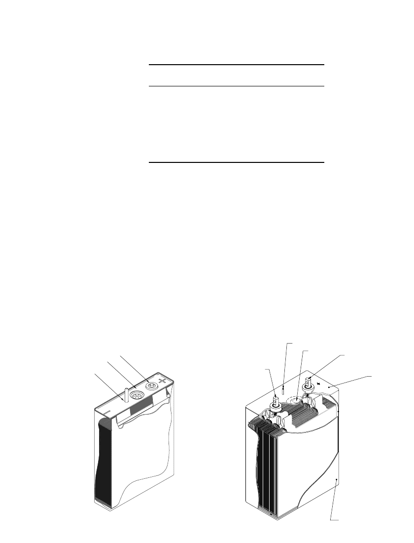
FIGURE 35.35 Schematic view showing the header and electrodes of 7 Ah (case negative) and 40
Ah (case neutral) flat plate prismatic Li-ion cells. (Courtesy of Yardney Technical Products, Inc.)
35.3.2 Construction of Flate-plate Prismatic Li-ion Batteries
The construction of flat-plate prismatic cells is illustrated in Fig. 35.35. As in a wound cell,
a microporous polyethylene or polypropylene separator separates the positive and negative
electrodes. Typically each plate in the cell has a tab, the tabs are bundled and welded to
their respective terminals or to the cell case. Cell cases of either nickel-plated steel or 304L
stainless steel have been used. As shown, the cover typically incorporates one or two ter-
minals, a fill port and a rupture disk. The terminal may be a glass-to-metal seal, for low cost
applications compression type seals have been used, or the terminal may incorporate devices
similar to those found in the header of cylindrical products to provide pressure, temperature
and over current interrupt in one component. The case to cover seal is typically formed either
by TIG or laser welding.

LITHIUM-ION BATTERIES 35.35
35.4 Li-ION BATTERY PERFORMANCE
The general performance characteristics of Li-ion batteries are outlined in Table 35.11. As
indicated in the table, Li-ion batteries have a high voltage, typically operating in the range
of 2.5 to 4.2 V, approximately three times that of NiCd or NiMH. As such, fewer cells are
required for a battery of a given voltage. Li-ion batteries offer high specific energy and
energy density, batteries with specific energy over 150 Wh /Kg and energy density over 400
Wh/ L are commercially available. Multiple-tabbed Li-ion batteries also offer high rate ca-
pability, up to 5C continuous or 25C pulse, thus high power density, and low self-discharge
rate, years of calendar life, no memory effect, and a broad temperature range of operation.
Li-ion batteries can be charged from
⫺20⬚Cto60⬚C and discharged from -40⬚Cto65⬚C.
The combination of these qualities within a cost effective, hermetic package has enabled the
diverse applicability of the technology.
TABLE 35.11 General Performance Characteristics of
Li-ion Batteries
Characteristic Performance range
Operational cell voltage 4.2 to 2.5 V
Specific energy 100 to 158 Wh / kg
Energy density 245 to 430 Wh /L
Continuous rate capability Typical: 1C
High rate: 5C
Pulse rate capability Up to 25C
Cycle life at 100% DOD Typically 3000
Cycle life at 20 to 40% DOD Over 20000
Calendar life Over 5 years
Self discharge rate 2 to 10% /month
Operable temperature range
⫺40⬚Cto65⬚C
Memory effect None
Power density 2000 to 3000 W / L
Specific power 700 to 1300 W / Kg
35.4.1 Characteristics and Sizes of Lithium Ion Batteries
As illustrated in Table 35.12 and Table 35.13, Li-ion batteries are available in a wide range
of sizes from 0.6 to 160 Ah in both cylindrical and prismatic designs with a range of aspect
ratios. Li-ion battery performance has steadily improved, in the period 1996 to 1999, the
specific energy of 18650-type cells increased 8% per year while energy density increased
14% per year, on average.
TABLE 35.12 Electrical and Physical Characteristics of Typical Cylindrical C/ LiCoO
2
or C /LiNi
1
⫺
x
Co
x
O
2
Li-ion
Batteries
Type 14500 14650 17500 17670 18500 18650 26650 33600
Height, mm 50.0 65 50 67 50 65 65 60
Diameter, mm 14 14 17 17 18 18 26 33
Volume, ml. 7.7 10 11.3 15.2 12.7 16.5 34.5 51.4
Mass, g. 19 26 25 35 31 42 93 125
Capacity (Ah) .65 .90 0.83 1.25 1.1 1.8 3.2 5.0
Specific energy (Wh/ kg) 126 128 123 132 131 155 354 150.4
Energy density (Wh/ L) 312 333 273 306 320 410 131 366

35.36
TABLE 35.13 Electrical and Physical Characteristics of Typical Prismatic C/ LiCoO
2
or C / LiNi
1
⫺
x
Co
x
O
2
Li-ion Batteries
Cell type 61/ 19/ 48 46 / 30 / 48 55 /30 /48 81 / 31 / 48 65/ 35/ 67 103 /34 /50 160 /61 /78 280 / 95/ 151 460/ 89/ 128 500 / 130 /208
Shape Prismatic (thickness (0.1 mm)/ width (mm)/ height (mm)
Height, mm 48 48 48 48 67.3 50 78 151 128 208
Width, mm 19.5 30 30 30.5 35.1 34.1 61 95 89 130
Thickness, mm 6.1 4.6 5.5 8.1 6.5 10.3 16 28 46 50
Volume, ml. 5.70 6.6 7.9 11.9 15.3 18.4 76 136 465 1352
Mass, g. 11.5 14 16 24 33 38 185 870 1108 3650
Capacity (Ah) 0.42 .52 0.6 0.9 .96 1.5 7.0 35 40 160
Specific energy (Wh/ kg) 135 137 138 139 104 146 145 145 156 160
Energy density (Wh/ L) 272 291 281 280 226 301 345 344 372 430
LITHIUM-ION BATTERIES 35.37
0.0 0.5 1.0 1.5
2.5
3.0
3.5
4.0
Voltage (V)
Discharge Capacity (Ah)
0.33 A (1.68 Ah)
0.82 A (1.67 Ah)
1.65 A (1.60 Ah)
2.00 A (1.53 Ah)
2.40 A (1.43 Ah)
3.60 A (1.37 Ah)
2.5
3.0
3.5
4.0
2.5
3.0
3.5
4.0
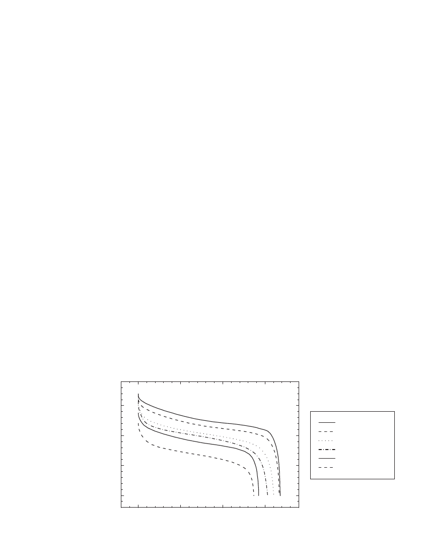
FIGURE 35.36 Discharge capability of 18650 type C/ LiCoO
2
batteries at constant current
at 21⬚Cto25⬚C. (Courtesy of the University of South Carolina and NEC Moli Energy.)
The most significant challenges to the broader application of Li-ion technologies are
related to either stability at high temperature or safety. While batteries may be exposed to
temperatures as high as 70
⬚C for short periods, the rate of degradation of current Li-ion
batteries is significant above 60
⬚C. Li-ion batteries are generally safe, although venting can
occur if they are overcharged or crushed. To vent from overcharge, batteries must typically
be charged to greater than 200% of their rated capacity. Protective devices are employed to
prevent ventings under abusive conditions.
In current Li-ion batteries, the overcharge, overdischarge and over temperature issues have
been largely addressed by the incorporation of management circuits into batteries to provide
protection from over-charge, over-discharge or over-temperature. In addition, the circuits may
also perform fuel gauge functions and can record battery history. The controller in the man-
agement circuit typically monitors the voltage of each cell or string of cells in a battery. In
addition, circuits typically include a thermistor or other thermostat for restorable over-
temperature control and a thermal fuse for non-restorable over-temperature control. Addi-
tional information on battery management circuits is found in Sec. 5.6.
35.4.2 Performance of Commerical Cylindrical Batteries
Discharge Rate Capability. The rate capability and capacity of Li-ion batteries are depen-
dent on their design, and varies considerably between manufacturers. Discharge curves for
18650-type C /LiCoO
2
batteries discharged at rates from 0.33 A to 3.6 A at 21⬚C are shown
in Fig. 35.36. At low rates (C/2), the battery provided 1.67 Ah, and at 1.65 A (the 1 C rate)
1.60 Ah while at the C rate the average voltage was 3.5 V.
Batteries utilizing the C/ LiMn
2
O
4
cell chemistry have also been commercialized. The
spinel cathode materials, as described in the section on cathode materials, are regarded as
providing lower cost and more benign safety properties relative to LiCoO
2
, although they
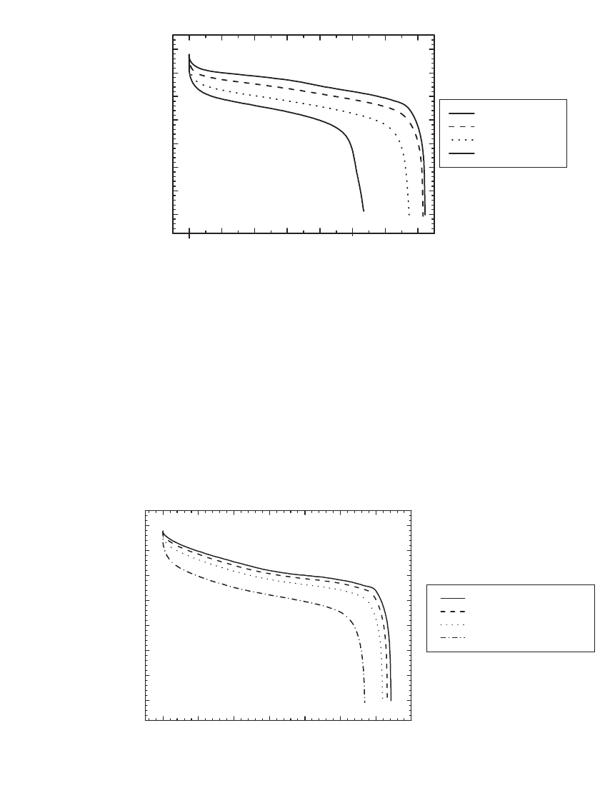
possess lower specific capacity. Shown in Fig. 35.37 is the rate capability and capacity of
18650-type C /LiMn
2
O
4
batteries. The products provide 1.44 Ah at the C /5 rate (0.28 A)
and 1.34 Ah at the C rate (1.4 A), comparable to, but less than the capacity of C/LiCoO
2
batteries. The discharge curves have a flat voltage profile with average voltage at the C rate
of 3.65 V, 0.15 V higher than C /LiCoO
2
cells at the C rate.
35.38 CHAPTER THIRTY-FIVE
0.0 0.2 0.4 0.6 0.8 1.0 1.2 1.4
2.50
2.75
3.00
3.25
3.50
3.75
4.00
4.25
Voltage (V)
Discharge Capacity (Ah)
0.28 A (1.44 Ah)
0.70 A (1.43 Ah)
1.40 A (1.34 Ah)
2.00 A (1.25 Ah)
FIGURE 35.37 Rate capability of an 18650-type C / LiMn
2
O
4
battery at constant current. The
battery was charged in a CCCV (constant current-constant voltage) regime at 1.4 A to 4.2 V for
2.5 hours, then discharged at 21⬚C. (Courtesy of NEC Moli Energy.)
01234567
2.50
2.75
3.00
3.25
3.50
3.75
4.00
4.25
Voltage (V)
Discharge Energy (Wh)
0.5W (1.69 Ah, 6.4 Wh)
1.0W (1.68 Ah, 6.3 Wh)
2.0W (1.67 Ah, 6.2 Wh)
5.0W (1.60 Ah, 5.7 Wh)
FIGURE 35.38 Constant power discharge of an 18650-type C / LiCoO
2
battery. The battery was charged
in a CCCV regime at 1.65 A to 4.2 V for 2.5 hours at 21⬚C. (Courtesy of NEC Moli Energy.)
The performance of Li-ion batteries under constant power discharge is illustrated in Fig.
35.38 for 18650-type C/LiCoO
2
batteries, and in Fig. 35.39 for an 18650-type C /LiMn
2
O
4
battery. At 1 W the C /LiCoO
2
battery provided 6.3 Wh, or 145 Wh /kg and 380 Wh/L. At
1 W the C/LiMn
2
O
4
battery provided 5.5 Wh, or 130 Wh/kg and 332 Wh/L.
The rate capability of several 18650-type batteries is compared in Fig. 35.40 which il-
lustrates the higher capacity of newer products and the 3C rate capability of the A&T
LSR18650 product. The average discharge voltage is lowered significantly at the higher rates.
