Lefebvre A.H., Ballal D.R. Gas Turbine Combustion: Alternative Fuels and Emissions
Подождите немного. Документ загружается.


330 Gas Turbine Combustion: Alternative Fuels and Emissions, Third Edition
wide variations in cooling-air quantity can occur between seemingly identi-
cal liners, owing to slight differences in wigglestrip material thickness. Even
small variations in metal thickness, within normal manufacturing tolerances,
can have a marked effect on coolant airow rate. Nevertheless, by careful
control of weld quality, and by ow-testing to check dimensional accuracy,
lm-cooling devices of the wigglestrip type have been used successfully on
a large number of American and British aero engines at pressure ratios up to
18–1. Rolls Royce engines featuring wigglestrip cooling include the Avon,
Spey, cannular Olympus, and Pegasus.
8.8.2 Stacked ring
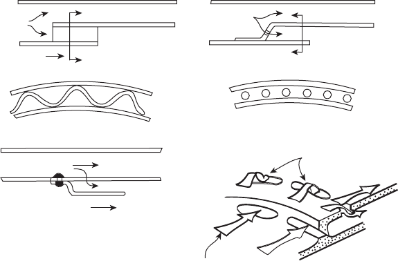
Another cooling device that uses total pressure feed is the “stacked ring,” as
shown in Figure 8.2b. Although it provides a less rigid form of liner construc-
tion than wigglestrips because the air-admission holes are drilled or punched,
their dimensional accuracy is higher, resulting in smaller variations in cooling
airow rate. The total ow area of these holes is calculated to meter the required
amount of cooling air. The aft end of the previous liner panel provides a plenum
in which turbulence is dissipated and the individual jets coalesce to form a sin-
gle annular sheet of air. At its downstream end, the gap width is dimensioned
to give the required cooling-air velocity. Thus, a useful asset of this arrangement
is that the cooling-air velocity can be xed at the optimum value for maximum
cooling effectiveness, regardless of the actual pressure drop across the liner.
Cool air
Cool air
Hot gas
View A-A
View B-B
B
B
Cool air
Hot gas
A
A
(a)
(b)
(c)
(d)
Total-pressure air feed
Static-pressure air feed
Figure 8.2
Film-cooling devices: (a) wigglestrip, (b) stacked ring, (c) splash-cooling ring, (d) machined
ring.
Heat Transfer 331
8.8.3 Splash-Cooling ring
This device uses only the static pressure drop across the liner wall as the
driving force for the injection of lm-cooling air (see Figure 8.2c). The cool-
ing air is bled from the annulus through a row of small holes in the wall
and is directed along the inside surface of the liner by means of an internal
deector “skirt” or “lip” that is attached to the wall by riveting or welding.
The function of the skirt is again to provide space in which the separate
air jets can merge to form a continuous sheet at the slot exit. A typical skirt
length is about four times the slot depth, which is usually of the order of
1.5–3.0 mm.
8.8.4 Machined ring
One concern with the stacked ring is the quality of the braze joint where the
rings are connected [1]. Conduction of heat through this joint is essential to
liner-wall cooling, and voids in the braze ller material can lead to local hot
spots. This problem does not arise in the “machined ring” liner, which is
machined either from a single piece of metal or from several rings welded
together. Rows of holes are then drilled to allow annulus air to enter the
cooling slot by either total-head feed, static pressure differential, or a combi-
nation of both, as illustrated in Figure 8.2d.
The machined ring offers advantages in terms of more accurate control of
cooling-air quantity and a marked improvement in the mechanical strength
of the liner, which is particularly important for large annular combustors.
Machined rings have acquired many millions of hours of operational ser-
vice on the Rolls Royce RB211 engine, and are specied for the RR Trent
combustor, where they will be used in conjunction with augmented external
convection and selective angled effusion cooling (AEC).
8.8.5 rolled ring
A drawback to both stacked and machined ring liners is that steep tempera-
ture gradients exist between the slot lip and the metal adjacent to the cooling
air feed holes. The lip inevitably has a high temperature because the cooling
air from the previous slot has lost its effectiveness, entrained hot gas, and is
now heating the liner wall instead of cooling it. On the other hand, the metal
near the cooling holes is immersed in air at combustor inlet temperature.
The resulting thermal gradients produce high stresses that can lead to liner
distortion and cracking [1].
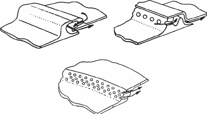
The General Electric rolled-ring liner, shown in Figure 8.3a, is fabricated
from a series of rings that are rolled into shape and welded together. In this
design, the static-pressure fed air jets provide impingement cooling to the
rolled ring before emerging from the slot as an effective cooling lm. Similar
design principles are employed in the Pratt and Whitney “double-pass” ring
shown in Figure 8.3b.

332 Gas Turbine Combustion: Alternative Fuels and Emissions, Third Edition
8.8.6 Z ring
As discussed above, the function of the skirt or lip is to allow the individual
cooling air jets to coalesce and form a continuous lm. Clearly, any reduction
in the initial diameter of these jets would allow a corresponding reduction
in the length of lip required. The extreme case of zero lip length is the Z-ring
slot, as illustrated in Figure 8.3c. This design was made possible by the
increased availability of EDM and laser drilling (or trepanning) techniques.
Using a large number of closely pitched, small-diameter holes ensures that
the jets coalesce quickly to form a uniform lm without needing the protec-
tion of a skirt.
In addition to its superior cooling performance in comparison to more
conventional cooling slots, the Z-ring design has another obvious advan-
tage in that it eliminates the life limitation due to skirt cracking. It also
lends itself to manufacture using ring rolling techniques, which give
good material utilization and produce contoured shells that need little
machining.
One drawback to the Z ring is the high cost of drilling a large number of
small holes. Improved manufacturing methods should alleviate this prob-
lem. There is also a need to control the land width between adjacent holes
and other critical dimensions to ensure satisfactory mechanical integrity
without loss of cooling performance.
Liners featuring Z-ring cooling have been tted to a number of Rolls Royce
military engines.
(a) (b)
(c)
Figure 8.3
Film-cooling devices: (a) GE rolled ring, (b) P&W double-pass ring, (c) RR Ζ ring.

Heat Transfer 333
8.9 Correlation of Film-Cooling Data
Almost all the theoretical and experimental studies of lm cooling carried
out so far have been aimed at nding parameters to describe the tempera-
ture of an adiabatic wall at any point downstream of the coolant injection.
The results of these investigations will now be examined, and later, it will be
shown how the data may be applied to a liner that is nonadiabatic due to the
heat uxes produced by ame radiation and external cooling.
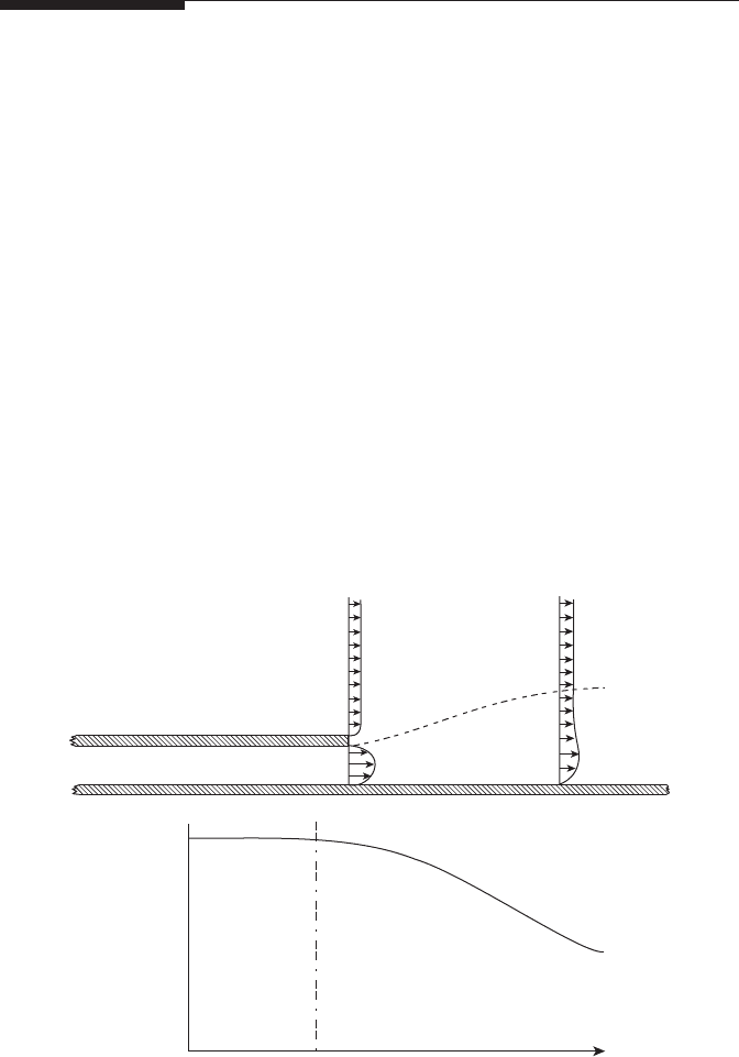
When a wall is lm cooled by injecting a stream of air between the sur-
face and the hot mainstream ow, three separate ow regions may be iden-
tied, as illustrated in Figure 8.4. According to Stollery and El-Ehwany [9],
the rst ow region comprises a potential core, in which the wall temper-
ature remains close to the coolant-air temperature. This is followed by a
zone where the velocity prole is similar to that of a wall jet. Further down-
stream, the ow conditions approximate those in a turbulent boundary layer.
The relative lengths of the three regions are governed mainly by the veloc-
ity ratio U
a
/U
g
. For U
a
< U
g
, the second zone is nonexistent, and a turbu-
lent boundary-layer model is appropriate for all regions downstream of the
potential core.
Hot gas
Cooling air
Jet boundary layer
T
a
, U
a
, m
.
a
, ρ
a
, A
s
T
g
U
g
m
.
g
ρ
g
A
g
1.0
0
0 x
η
Figure 8.4
Schematic of lm-cooling process. (Reprinted from Stollery, J.L. and El-Ehwany, A.A.M.,
International Journal of Heat and Mass Transfer, 8(1), 55–65, 1965. With permission from
Elsevier.)

334 Gas Turbine Combustion: Alternative Fuels and Emissions, Third Edition
8.9.1 Theories Based on Turbulent Boundary-Layer Model
Stollery and El-Ehwany [9] used a turbulent boundary-layer model to derive
the following expression for lm-cooling effectiveness.
η=
−
309
08
.,
.
S
(8.30)
where η, the lm-cooling effectiveness, is
η=
−
−
TT
TT
gw.ad
ga
,
(8.31)
and
S
x
ms
= Re ,
.
s
025
(8.32)
where
s is the depth of the lm-cooling slot, x is the distance downstream of
the slot, m is (ρU)
a
/(ρU)
g
, and Re
s
is the slot Reynolds number = U
a
ρ
a
s/µ
a
.
When Stollery and El-Ehwany compared their theoretical formula with the
experimental data of other workers, they found that a better correlation
could be obtained by increasing the value of the constant from 3.09 to 3.68
and slightly modifying the correlation group to give
η
µ
µ
=
−
368
08
02
.Re.
.
.
x
ms
s
a
g
(8.33)
A drawback to this equation and to all others based on the Blasius
skin-friction relationship is that they relate to an idealized turbulent
boundary layer far downstream of the slot. Thus, they cannot satisfacto-
rily describe the ow situation near to the slot, which is of prime inter-
est for the gas turbine. This suggests that a better model for this region
would be one that employed skin-friction coefcients obtained by direct
measurement in this zone. From a study of skin-friction data, Ballal and
Lefebvre [10] derived the following expression for effectiveness in the
near-slot region:
η
µ
µ
=
−
06
03
015
.Re.
.
.
x
ms
m
s
a
g
(8.34)

Heat Transfer 335
This equation was found to predict, to ±5% accuracy, all the available experi-
mental data within the following ranges of conditions:
Parameter Range
m 0.5–1.3
ρ
a
/ρ
g
0.8–2.5
s 0.19–0.64 cm
x/s 0–150
8.9.2 Theories Based on Wall-Jet Model
If the velocity of the cooling air is signicantly higher than that of the main
stream, the ow emerging from the slot behaves more like a jet than a
boundary layer. This jet model applies, of course, only in regions close to
the slot. Further downstream, the ow conditions revert to the boundary-
layer type.
The wall-jet model of Ballal and Lefebvre [10] leads to the following expres-
sions for effectiveness, for 1.3 < m < 4.0:
For x/ms < 8:
η=1. .0
For 8 < x/ms < 11:
η= +
−
06 005
1
.. .
x
ms
(8.35)
For x/ms > 11:
η
µ
µ
=
−
−
07
03
015
02
.Re.
.
.
.
x
s
m
s
a
g
(8.36)
Values of effectiveness based on these expressions agree quite closely with
published experimental data [10].
Equations 8.35 and 8.36 may be applied to the near-slot regions of all two-
dimensional “clean” slots, provided that the thickness of the slot lip is small
in relation to the slot height. However, for mechanical integrity, the lip is
sometimes made quite thick; in that case, a wake region is created behind
it, which tends to shorten the length of the potential core and extend the
transition zone.
From an analysis of available experimental data concerning the inuence
of slot-lip thickness, t, on effectiveness, Ballal and Lefebvre [11] derived an

336 Gas Turbine Combustion: Alternative Fuels and Emissions, Third Edition
empirical “correction factor” that, when applied to Equations 8.34 and 8.36,
gives, for 0.5<m <1.3,
η
µ
µ
=
−
110
065
015
02
.
.
.
.
m
x
s
t
s
a
g
−02.
,
(8.37)
and for 1.3<m <4.0,
η
µ
µ
=
−−
128
015
02 0
.
.
..
a
g
x
s
t
s
22
.
(8.38)
It should be noted that Equation 8.38 is recommended for all values of x/ms
because the additional accuracy given in Equation 8.35 for thin-lipped sys-
tems is lost when t/s exceeds 0.2, owing to the inuence of lip thickness on
effectiveness in this very-near-slot region [12]. Thus, the use of two separate
equations for the wall-jet model is unnecessary in thick-lip situations.
A comparison of Equations 8.37 and 8.38 shows that, apart from a
small difference in the value of the constant, the only signicant differ-
ence is in regard to the inuence of m. According to Equation 8.37, an
increase in m should improve effectiveness, whereas Equation 8.38
implies that effectiveness is independent of the value of m. This apparent
anomaly arises because of the contrasting effects produced by a change
in m, which depend on whether the initial value of m is greater or less
than unity. When m<1, an increase in m improves lm-cooling effective-
ness in two ways: (1) through a relative increase in the amount of coolant
air, and (2) through a reduction in the rate of mixing between the cool-
ant and mainstream gases as m approaches unity. However, when m >1,
any further increase has two opposing inuences on cooling effectiveness.
The relative increase in coolant ow is again benecial, but this effect is
countered by a more rapid rate of mixing between the coolant and main-
stream ows as m departs further from unity. This causes an increase in
the thickness of the boundary layer, which consequently embraces a larger
amount of mainstream gas. The net result is that effectiveness is sensibly
independent of m.
In many early designs of gas turbine combustion chambers, unfortunately
the cooling slots are not clean, but contain obstructions of various kinds. These
reduce effectiveness by generating turbulence and enhancing mixing rates.
The effectiveness of such practical lm-cooling slots has been investigated
in detail by Sturgess [13]. His equation for the prediction of effectiveness may
be written in a slightly simplied form for machined-ring devices as
η= −10 012
065
.. ,
.
S
N
(8.39)

Heat Transfer 337
and for stacked-ring devices as
η= −10 0094
065
.. ,
.
S
N
(8.40)
with
S
xx
ms
A
A
N
=
−
−
p
a
g
o
eff
Re ,
.
µ
µ
015
where x
p
is the potential core length, A
o
is the slot outlet area, and A
eff
is the
slot overall effective area.
These equations were found by Sturgess to correlate measured values of
effectiveness from a number of machined-ring and stacked-ring geometries
to an accuracy of within 10%.
To summarize, for “dirty” cooling slots of the type still used in many gas tur-
bine combustors, it is recommended that Equations 8.39 or 8.40, due to Sturgess,
be used to predict effectiveness. For thick-lipped systems in which the slot
geometry is sensibly “clean,” it is suggested that Equations 8.37 and 8.38 be
used for m<1.3 and m>1.3, respectively, over the range of x/s from 0 to 50.
8.9.3 Calculation of Film-Cooled Wall Temperature
In the calculation of lm-cooled wall temperatures, the previously derived
expressions for R
1
, R
2
, and C
2
remain the same, but the internal-convection
component, C
1
, is altered because the coolant ow changes both the velocity
and temperature of the hot gas near the wall. Dealing with velocity rst, we
have [11] for 0.5<m <1.3,
Nu
x
s
=
0069
07
.Re,
.
s
(8.41)
leading to
C
k
x
TT
x1
07
0069
1
=−.Re( ),
.
a
w.ad w
(8.42)
where
Re .
x
U
x
=
aa
a
ρ
µ

338 Gas Turbine Combustion: Alternative Fuels and Emissions, Third Edition
For m>1.3,
Nu
x
s
=
010
08
044
.Re,
.
.
s
(8.43)
leading to
C
k
x
x
s
TT
x1
08
036
010
1
=
−
−
.Re().
.
.
a
w.ad w
(8.44)
The gas temperature, T
w,ad
, at the wall is obtained from the denition of η,
given in Equation 8.31 as:
η=
−
−
TT
TT
gw.ad
ga
,
where η is the effectiveness value calculated from Equations 8.37 or 8.38 for
clean slots, and Equations 8.39 or 8.40 for dirty slots.
example
For the combustor of the previous example, let us calculate the liner-wall tempera-
ture at a distance x downstream of the slot, where x/s = 18.
We first calculate the slot parameters. From the liner geometry, we know that
x
s
t
s
s===18 04 0 00145..m,
AD
sL
Sm==×
−
π 59510
42
..
Thus
x =× =18 0 00145 0 0261..m,
mUA
saas
kg/s.==ρ 0 289.
Hence
ρ
aa
2
kg msU =⋅485 7./().
For air at 880 Κ and a pressure of 3040 kPa,
µ
a
kg/ ms=× ⋅
−
38910
5
.(),
k
a
W/(m K).=⋅0 0553.

Heat Transfer 339
Therefore,
Re .,
s
aa
a
==×
ρ
µ
Us
18110
4
Re ..
x
Ux
==×
ρ
aa
a
µ
32610
5
To determine the mainstream parameters, we have,
A
L
m= 0 0137
2
.,
T
g
K,= 2280
µ
g
kg ms=× ⋅
(
)
−
70510
5
./,
q
pz
= 005.,
mUA
gggL
kg/s,==ρ 262.
k
g
WmK=⋅
(
)
0 157./.
Hence,
ρ
gg
2
kg/(m sU == ⋅
262
0 137
191
.
.
).
To calculate the film-cooling effectiveness, we note that
m
U
U
== =
ρ
ρ
aa
gg
485 7
191
254
.
..
Since m>1.3, it is appropriate to use Equation 8.38:
η
µ
µ
=
=
−
128128
389
015
2
02
..
.
.
.
a
g
xt
s
7705
18 04 0 789
015
02
.
(.)..
.
.
×=
−
Now
η=
−
−
=
−
−
TT
TT
T
g w,ad
ga
w.ad
2280
2280 880
.
Hence, T
w,ad
= 1176 K.
