Koren B., Vuik K. (Editors) Advanced Computational Methods in Science and Engineering
Подождите немного. Документ загружается.


S. van der Hoeven, B.J. Boersma, and D.J.E.M. Roekaerts
properties are tabulated as a function of resolved mixture fraction and variance of
mixture fraction.
The variance of mixture fraction is estimated with a simple gradient model,
which can be derived from local equilibrium arguments [8]:
g
Z”
2
= C
Z
∆
2
∂
˜
Z
∂
x
i
∂
˜
Z
∂
x
i
, (21)
with C
Z
being 0.2. Resolved temperature, mean molecular weight, specific heat
and temperature dependent viscosity are stored in the look up table. The steady
flamelet model (without extinction model) is sufficiently accurate to describe the
Sandia flame D, discussed below. At this stage our main focus is on testing the
compressible code in combination with scalar transport rather than on the chemistry
model itself. When using (adiabatic) flamelet methods in low-Mach number codes it
is sometimes possible to replace the energy equation with the flamelet temperature
solution. However, for compressible formulations this cannot be done in general,
due to the presence of finite acoustic time scales (influence of pressure variations on
the energy). In order to couple the flamelet solution in the compressible code while
retaining acoustics we use a simple relaxation method to bring the system at the
flamelet temperature solution. The energy equation is solved with the heat release
source term given by a relaxation term:
¯
˙
ω
f
= −
¯
ρ
¯c
V
e
T −
e
T
f
/
τ
f
, (22)
where
e
T
f
is the flamelet temperature and
τ
f
is the relaxation time constant. The
effect of using such a flamelet source term was investigated using 1D simulations.
Different values for
τ
f
were tested. It was observed that when a too small time con-
stant is used stability problems arise due to large flow dilatation and on the other
hand using time constants larger than the integral time scale of the flow results in
inactive behavior (hot gas mixing). It was observed that a time constant of approxi-
mately 15u
0
/D, where u
0
is the maximum jet velocity at the inlet and D the nozzle
diameter, works most efficiently. Therefore we use this value in the 3D simulations.
4 Numerical method
The LES filter introduces a certain cut-off in the wave number spectrum, see Figure
1. Wave numbers which are smaller than the cut-off wave number are resolved by
the numerical scheme. Wave numbers which are larger than the cut-off frequency
have to be modelled with a subgrid model. A common approach is to take the cut-
off wave number equal to the grid resolution, the so-called implicit LES filter. A
better but more elaborate approach is to use an explicit filter which has a cut-off
wavelength which is larger than the grid resolution. In this paper we will follow the
274

Large Eddy Simulation of Jet Flames
first approach, i.e. the grid resolution equals the cut-off wavenumber and hence no
explicit filtering will be performed.
The unresolved (or subgrid scales) are in general responsible for the dissipation
of kinetic energy and also for the diffusion of temperature and species fluctuations.
The main task of any subgrid model is to provide the required dissipation or diffu-
sion rate. Unfortunately, any numerical method will also provide a certain amount
of dissipation of diffusion. In LES the dissipation or diffusion is in general a mix-
ture of numerical diffusion and model diffusion. Numerical diffusion can be very
useful to stabilize computations, but it is in general unwanted, because it does not
only depend on gradients in the flow but also on the quality of the grid.
In this study we will use methods that minimize the numerical diffusion. This
more or less rules out all (low order) upwind methods. Schemes with a purely central
discretization in general do not introduce significant numerical dissipation.
4.1 The derivative
In the equations given previously only first order spatial derivatives appear. There-
fore, we will only discuss first order derivatives. The simplest central scheme for
the 1st derivative is the classical second order scheme, which reads for a function
f
i
= f(i
∆
x):
f
′
i
=
f
i+1
− f
i−1
2
∆
x
+ O(
∆
x
2
), (23)
where
∆
x is the grid spacing. Here we will assume that the function f
i
can be written
as a Fourier series
f
i
= f(i
∆
x) =
∑
k
ˆ
f (k)exp( jki
∆
x), (24)
in which j =
√
−1 is the imaginary unit and k a wave number. With help of this
Fourier series it is easy to derive the error of the finite difference scheme as a func-
tion of the wavenumber k. The result reads:
error(k
∆
x) = 1 −
sin(k
∆
x)
k
∆
x
. (25)
Is is clear that the discretization error made by the scheme is small for small values
of the wavenumber k and rather larger for large values of k. If we use this scheme
for our Large Eddy Simulation, we will have a large error close to the cut-off wave-
length of the LES filter and therefore this is scheme is unwanted. A simple extension
of the scheme would be to add two points on the right hand side, i.e:
f
′
i
=
8
12
f
i+1
− f
i−1
∆
x
−
1
12
f
i+2
− f
i−2
∆
x
+ O(
∆
x
4
). (26)
This is the classical fourth order scheme. The error as a function of the wavenumber
k is given by
275
S. van der Hoeven, B.J. Boersma, and D.J.E.M. Roekaerts
error(k
∆
x) = 1 −
4
3
sin(k
∆
x)
k
∆
x
+
1
6
sin(2k
∆
x)
k
∆
x
. (27)
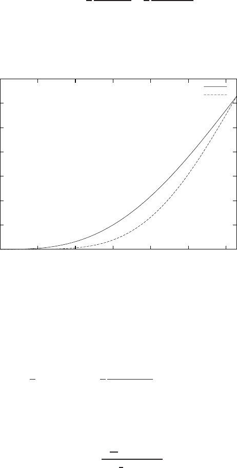
The errors for the second and fourth order scheme, equations (22) and (24), are
plotted in Figure 2. The fourth order scheme is better than the second order scheme
but both are fairly inaccurate for wavenumbers larger than 1.5.
0
0.5
1
1.5
2
2.5
3
3.5
0 0.5 1 1.5 2 2.5 3
error(k dx)
k dx
2nd order
4th order
Fig. 2 The error as a function of the wave number k
∆
x for a 2nd and 4th order finite difference
scheme
The numerical accuracy for the large wave numbers can be greatly increased
by using a so-called compact formulation of the finite difference formulation. This
formulation reads in its most simple form:
f
′
i
+
1
4
[ f
′
i−1
+ f
′
i+1
] =
3
4
f
i+1
− f
i−1
∆
x
+ O(
∆
x
4
). (28)
The actual evaluation of this scheme requires the solution of a tridiagonal system
and is therefore computationally more expensive than the standard fourth order
schemes. We can write the following relation for the error
error(k
∆
x) =
18
12
sin(k
∆
x)
1 +
1
2
cos(k
∆
x)
. (29)
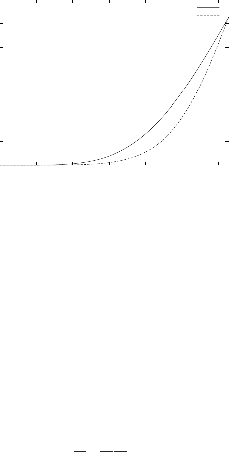
This error is considerably smaller than the error of the central fourth order scheme,
see Figure 3.
In the literature mostly the 6th order compact scheme is used. This scheme is
constructed by adding two additional points to the righthand side of equation (25)
and evaluating the coefficients by a Taylor expansion.
276
Large Eddy Simulation of Jet Flames
0
0.5
1
1.5
2
2.5
3
3.5
0 0.5 1 1.5 2 2.5 3
error(k dx)
k dx
4th order
4th order compact
Fig. 3 The error as a function of the wave number k
∆
x for a 4th order central and a fourth order
compact scheme.
The drawback of compact schemes for non-linear problems such as the Navier-
Stokes equations is the fact that these schemes are fairly unstable. Due to the low
dissipation error of the numerical scheme it is not possible to ”under resolve” certain
wavelengths. A large eddy simulation is by definition under resolved and therefore
compact schemes are not very suited for LES. Common practice is to use a high
order compact filter to remove the short wave instabilities. This type of approach
works but also introduces an artificial viscosity and is therefore unwanted for large
eddy simulation.
Recently, staggered variants of the compact schemes have been proposed by [4,
1]. These schemes turn out to be much more stable and can be used when the grid
is not sufficiently fine to resolve all scales of motion. In this paper we will adopt the
staggered method as proposed in [1]. In this method the vector quantities are stored
at the cell faces and all scalar quantities are stored in the cell centers. Compact
differentiation and interpolation rules are used to calculate the necessary quantities
on the computational grid. This is all done with a 10th order accurate scheme. On
non-uniform grids a mapping of the form
d f
dx
=
d f
d
η
d
η
dx
is used. Here x is the non-uniform coordinate,
η
the uniform coordinate and the first
derivatived
η
/dx is a known analytical function which is non-zero inside the compu-
tational domain. In this way we can calculate the derivatives on a non-uniform grid
without any additional errors. For the interpolation on the non-uniform grids we use
the same rule as for a uniform grid. This is strictly speaking not correct. We have
277
S. van der Hoeven, B.J. Boersma, and D.J.E.M. Roekaerts
chosen for this approach because only in this way we are sure that the discretization
of the first-order derivative is purely symmetric and thus does not introduce any arti-
ficial dissipation or diffusion, [5]. The error we make in the interpolation procedure
can be controlled by generating grids with very small differences in mesh widths of
neighboring cells.
4.2 Time discretization
For the time discretization we use a standard fourth order Runge-Kutta method. For
a linear advection diffusion problem the time step limitation for the RK4 scheme is
approximately 2.8 based on a CFL type criterion. For the present problem, which is
strongly non-linear, we use a fixed time step
∆
t the value of
∆
t corresponds roughly
to a CFL number of 1.0.
4.3 The discretization of the Navier-Stokes equations for the
SANDIA flame D problem
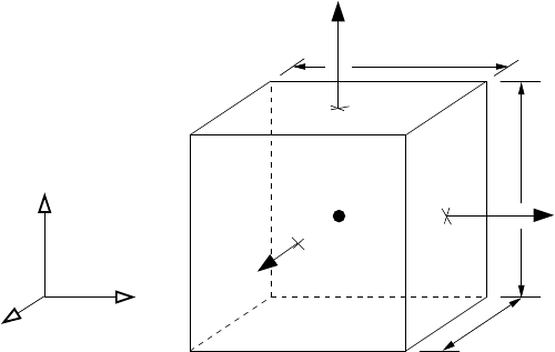
The 3D equations are discretized on a staggered non-uniform Cartesian grid in phys-
ical space. A typical grid volume is shown in Figure 4. The non-uniform grid is
z
x
y
v
u
i,j+1/2,k
x
∆
i,j,k+1/2
w
y∆
∆z
p
i,j,k
φi,j,k
ρi,j,k
µi,j,k
i+1/2,j,k
Fig. 4 The layout of the staggered grid. The vector quantities are stored at the cell faces, and the
scalar quantities at the cell centers.
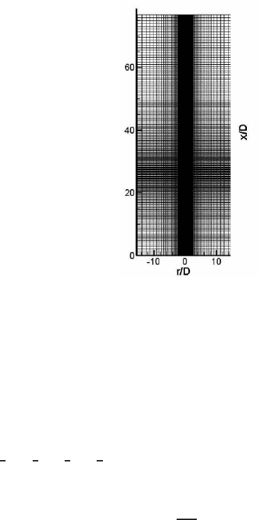
constructed with hyperbolic sine and tangent functions to cluster the majority of
grid points in the high-strain region of the jet. A typical distribution of the grid
is shown in Figure 5. The circular fuel nozzle surrounded by an annulus of pilot
278
Large Eddy Simulation of Jet Flames
Fig. 5 A typical non-uniform grid used for the combustion simulations.
mixture and an annulus of air are located in the y −z plane at x = 0. Simulations
were performed on a 200× 96×96 (X×Y×Z) grid with in x and y direction ap-
proximately 40 points in the nozzle region to resolve the strong jet shear-layers.
The dimensions of the computational domain are 70×30×30 nozzle diameters.
For the calculation of the derivative of a certain variable f on the non-uniform
grid we map f on a corresponding uniform grid. The first-order derivative is al-
ways calculated on the uniform grid. When a variable is known on the cell faces,
...,i −
3
2
,i −
1
2
,i +
1
2
,i +
3
2
,...
the following formula is used to find the derivative
at the center of the cell, [...,i −1, i,i + 1, ...]:
f
′
i
+ a
0
f
′
i+1
+ f
′
i−1
=
4
∑
n=1
a
n
∆
X
f
i+(2n−1)/2
− f
i−(2n−1)/2
. (30)
Thus, the variable is implicitly swapped from the cell face to the cell center. In
equation (30) f
′
is the derivative of a certain variable f with respect X, i.e. d f /dX in
grid point i.
∆
X is the uniform grid point distance. The coefficients a
i
can be found
with Taylor expansions around grid point i. Having the coefficients a
0
,..,a
3
it is
theoretically possible to achieve tenth-order accuracy, but close to the boundary the
stencil is made smaller, since one-sided differences are applied there. Interpolation
is carried out with the following formula:
f
i
+ b
0
( f
i+1
+ f
i−1
) =
4
∑
n=1
b
n
f
i+(2n−1)/2
+ f
i−(2n−1)/2
. (31)
279

S. van der Hoeven, B.J. Boersma, and D.J.E.M. Roekaerts
n 0 1 2 3 4
a
n
49/190 12985/14592 78841/364800 -343/72960 129/851200
b
n
7/18 1225/1536 49/512 -7/1536 1/4608
Table 1 Coefficients for the derivative and interpolation rule with a tenth-order stencil.
5 Boundary conditions
Since the developed code is low-dissipative, (acoustic) waves can reflect at the do-
main boundaries and disturb the flow. Therefore special attention must be paid to
the treatment of the boundaries. Different boundary condition methods were imple-
mented and tested. The class of methods using characteristic boundary conditions
is attractive since it allows to control the behavior of characteristic waves in a di-
rect way. We have implemented the Navier-Stokes Characteristic Boundary Condi-
tions (NSCBC) method of Poinsot and Lele [9] in our staggered grid arrangement.
The NSCBC method works well for combustion simulations where acoustics are
unimportant, but for a staggered grid it appeared to be computationally expensive to
define all necessary quantities locally at the cell faces. This holds especially for sub-
sonic outflow conditions. Another drawback of (linearized) characteristic BC’s such
as the NSCBC method is that it is very difficult to convect a hot jet flow out of the
domain without using artificial sponge layers. This is due to the multi-dimensional
nature of the structures in jet flows for which a simple pressure relaxation method
is not good enough. Yoo et. al. [10] proposed to solve the problem by extending the
NSCBC method with multi-dimensional corrections.
We follow another procedure which is a variant of the methods proposed by Colo-
nius et. al. [11], Ta’asan et. al. [12] and Berenger [13]. This method was applied by
Freund [14] in aeroacoustics simulations. In this procedure the computational do-
main contains a non-physical boundary region where extra boundary terms appear
in the governing transport equations (Fig. 6). This non-physical region uses nearly
one percent of the total amount of grid points. Several approaches can be followed
within this boundary domain, and we have combined two of them. The first is to
force the solution towards some target solution, by adding a term
σ
(
φ
−
φ
target
) to
the transport equation for
φ
:
∂φ
∂
t
= RHS +
σ
(
φ
−
φ
target
), (32)
where
φ
is a conserved quantity, RHS stands for all terms of the unforced equation
and
σ
is a forcing parameter being nonzero only in the artificial boundary layer.
φ
target
can be a time-averaged value or a known solution, e.g. from a RANS cal-
culation [15]. The second approach is to add a term which gives disturbances an
increased convection velocity according to a given profile which is supersonic in
the unphysical region and decreases to zero at the interface between unphysical and
physical region. The latter terms prevent that at the in- and outlet boundaries reflec-
tions travel backwards into the domain. This is done in the following way:
∂φ
∂
t
= RHS −U
c
∂φ
∂
x
, (33)
280
Large Eddy Simulation of Jet Flames
where U
c
is the given velocity profile, being nonzero only near the inlet and out-
let plane. At the lateral boundaries we prescribed a simple reflecting characteristic
boundary condition with fixed velocities. Although such a boundary condition al-
lows waves to reflect, any disturbance is damped by forcing the solution to the time-
averaged solution as proposed in eq. (32).
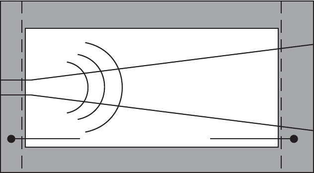
Artificial boundary region (σ≠0)
Physical domain (σ=0)
Inlet boundary
Supersonic convection layer
Acoustic radiation
Outlet boundary
Fig. 6 Schematic view of computational domain with artificial boundary layer.
In order to minimize non-physical behavior at the walls originating from 2
∆
x in-
stabilities we applied explicit filtering every 25 time steps in the artificial bound-
ary region. At each boundary of the computational domain, only the component of
velocity orthogonal to that boundary is filtered. (We recall that the computational
domain is a rectangular box.) We have used a filter of the form:
ˆ
φ
n
=
φ
n−3
−6
φ
n−2
+ 15
φ
n−1
+ 44
φ
n
+ 15
φ
n+1
−6
φ
n+2
+
φ
n+3
, (34)
which filters 2
∆
x waves from the solution. In the vicinity of the walls the filter
stencil is adjusted to one-sided differences.
5.1 Parallel implementation
The model described above has been implemented in Fortran77/Fortran90 and par-
allelized with the message passing interface MPI. The parallel implementation of
the model will be described in this section.
The total calculation consists of N
x
×N
y
×N
z
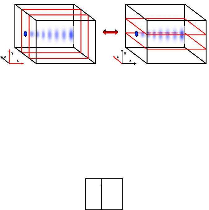
grid points. We use two data distri-
butions, one with N
x
×N
y
×(N
z
)/P points, where P is the number of processors and
one with N
x
×(N
y
)/P ×N
z
, see Figure 7. On the first distribution we can calculate
281
S. van der Hoeven, B.J. Boersma, and D.J.E.M. Roekaerts
all the derivatives in the x and y direction. On this distribution only a part of the z
direction is available and we can not calculate the z derivatives. For the z deriva-
tives we use the second data distribution. The z derivatives are communicated to the
first distribution and the Runge-Kutta (sub)steps on the first distribution. After the
Runge-Kutta (sub)step all values are communicated to the second data distribution
and a new (sub)step can be performed.
Fig. 7 The decomposition of the computational domain in a distribution with N
x
×N
y
×(N
z
)/P
and with N
x
×(N
y
)/P ×N
z
points.
All the communication is performed with the MPI routine MPIALLTOALL. Due
to the implicit nature of the compact differences we need all points in a specific
direction to be present on a single CPU and we can not use nearest neighbor com-
munications as is used in standard finite difference codes.
Due to global nature of the communication our model only works on parallel
computers with very efficient communication hardware. The model will run on a Be-
owulf cluster but it will be slow. On modern supercomputers, like the IBM-SP5/SP6
the model works well up to a large number of CPUs as can be seen from table 1.
Table 2 Times of the numerical model obtained on an IBM-SP5
# CPU time/step
2 34 sec
4 21 sec
8 13 sec
16 7 sec
6 Simulation details
Laminar inflow conditions were prescribed at the inlet section. Since the flow is
locally supersonic we may prescribe all variables:
¯
ρ
, eu, ev, ew,
e
E and
e
Z. The axial ve-
282
Large Eddy Simulation of Jet Flames
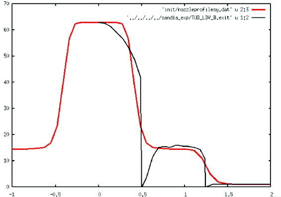
locity and mixture fraction profiles were taken from experimental data [6] and re-
constructed with polynomial approximations. The inflow profile in the experiment
has very large gradients, see Figure 8, and these large gradients could not be re-
constructed with the present fairly course grid resolution. The difference between
inflow profiles in the simulations and experiments will remain visible throughout
the whole simulation.
Fig. 8 The inflow profile from the SANDIA experiment and our polynomial fit.
The flame simulations are performed by starting with a cold flow simulation. After
the cold jet has developed completely the flamelet relaxation term as specified in
Equation (22) is added to the energy equation. With this approach the temperature
in the LES model approaches the flamelet temperature as can be seen from Figure
9.
In figure 10 we show contour plots of the Favre-averaged velocity, the eddy vis-
cosity and the Favre-averaged temperature. The region outside the black box is the
non-physical region where additional terms to handle boundary conditions have
been added. In Figure 11 we compare the predicted radial profiles of time aver-
aged resolved axial velocity and the variance of the axial velocity fluctuations, with
the experimental data. Overall the agreement between the simulations and experi-
ments is reasonable. The difference between experiment and simulation can be due
to several reasons. The main reason is probably the difference in the inflow pro-
files as shown in Figure 8, and the fact that laminar inflow profiles were assumed in
the simulations. The predicted time averaged resolved temperature profiles and the
standard deviation of temperature are compared with experimental results in Fig-
ure 12. Again we observe a reasonable agreement. The agreement is not as good as
what has been obtained using a RANS model [20, 21] but comparable to earlier low
283
