Kamal A.A. 1000 Solved Problems in Classical Physics: An Exercise Book
Подождите немного. Документ загружается.

540 12 Electric Circuits
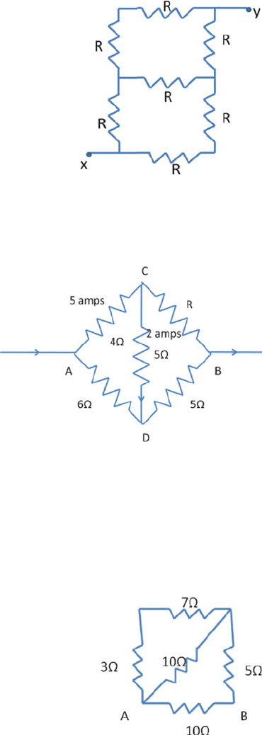
12.7 Find the equivalent resistance between the terminals x and y of the network
shown in Fig. 12.7.
Fig. 12.7
12.8 A circuit is set up as shown in Fig. 12.8, in which certain resistors are known;
the current in some of the branches has been measured by ammeter.
Calculate
Fig. 12.8
(i) The resistance R in CB
(ii) The potential difference between A and B
(iii) The heat developed per second between A and B.
[Northern Universities of U.K.]
12.9 Five resistances are connected as shown in Fig. 12.9. Find the equivalent resis-
tance between the points A and B.
Fig. 12.9
12.2 Problems 541
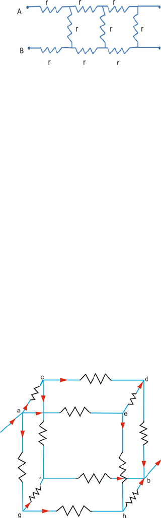
12.10 A network of infinite resistors is shown in Fig. 12.10. Find the effective resis-
tance of the network between terminal points A and B.
Fig. 12.10
12.11 What equal length of an iron wire and a constantan wire, each 1 mm diameter,
must be joined in parallel to give an equivalent resistance of 2 ? (resistivity
of iron and constantan are 10 and 49 μ cm, respectively).
[University of London]
12.12 A coil of wire has a resistance of 20 at 25
◦
C and 25.7 at 100
◦
C. Calcu-
late the temperature coefficient.
[University of London]
12.13 A wire of resistance 0.1 /cm is bent to form a square ABCD of side 10 cm.
A similar wire is connected between the corners B and D to form the diag-
onal BD. Find the effective resistance of this combination between A and
C. A battery of negligible internal resistance is connected across A and C.
Calculate the total power dissipated.
[Indian Institute of Technology 1971]
12.14 A 60 W-100 V tungsten lamp has a resistance of 20 at air temperature
(0
◦
C). What is the rise in temperature of the filament under normal work-
ing conditions? The temperature coefficient of resistance of tungsten is
0.0052/
◦
C.
[University of London]
12.15 A skeleton cube is made of wires soldered together at the corners of the cube,
the resistance of each wire being 10 . A current of 6 A enters at one corner
Fig. 12.11
542 12 Electric Circuits
and leaves the diagonally opposite corner. Calculate the equivalent resistance
of the network and the fall of potential across it (Fig. 12.11).
[University of London]
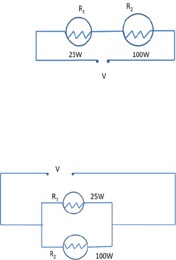
12.16 A 25 W bulb and a 100 W bulb are joined in series and connected to the
mains (Fig. 12.12). Which bulb will glow brighter?
[Indian Institute of Technology 1979]
Fig. 12.12
12.17 A 25 W bulb and a 100 W bulb are joined in parallel and connected to the
mains (Fig. 12.13). Which bulb will glow brighter?
Fig. 12.13
12.18 Three resistors of 4, 6 and 12 are connected together in parallel. This par-
allel arrangement is then connected in series witha1and2 resistors. If
a potential difference of 120 V is applied across the end of the circuit, what
will be the potential drop across the part of the circuit connected in parallel?
[University of Newcastle]
12.19 In the given circuit, Fig. 12.14, show that the maximum power delivered to
the external resistor R is P = ξ
2
/4r where r is the internal resistance of the
battery of emf ξ.
12.2 Problems 543
Fig. 12.14
12.20 Two heater coils of power P
1
and P
2
(resistance R
1
and R
2
, respectively)
take individually time t
1
and t
2
to boil a fixed quantity of water. Find the
time t in terms of t
1
and t
2
, when they are connected to the mains in (a)
series and (b) parallel to boil the same quantity of water.
12.21 A battery having an emf 24 V and a resistance 2 is connected to two resis-
tances arranged (a) in series and (b) in parallel. If the resistances are 4 and
6 , respectively, calculate the watts expended in each resistance, in each of
the two cases.
[University of London]
12.22 Power at the rate of 10
4
kW has to be supplied through 30 km of cable of
resistance 0.7 /km. Find the rate of energy loss, if the power is transmitted
at 100 kV.
[University of Dublin]
12.23 Three equal resistors, connected in series across a source of emf together,
dissipate 10 W of power. What would be the power dissipated, if the same
resistors are connected in parallel across the same source of emf?
[Indian Institute of Technology 1972]
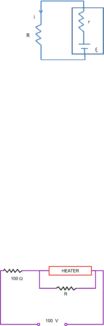
12.24 A heater is designed to operate with a power of 1000 W in a 100 V line. It is
connected in combination with a resistance of 100 and a resistance R to a
100 V mains as shown in Fig. 12.15. What should be the value of R so that
the heater operates with a power of 62.5 W?
[Indian Institute of Technology 1978]
Fig. 12.15
544 12 Electric Circuits
12.2.2 Cells
12.25 Twelve cells having the same emf are connected in series and are kept in
a closed box. Some of the cells are wrongly connected. This battery is
connected in series with an ammeter and two cells identical with others. The
current is 3 A when the cells and the battery aid each other and is 2 A when
the cells and the battery oppose each other. How many cells in the battery are
wrongly connected?
[Indian Institute of Technology 1976]
12.26 Let there be m rows of cells with each row containing n cells in series, each
cell having internal resistance r. Show that maximum current in the external
resistance R will be available when R = nr/m.
12.27 Two cells with the same emf and internal resistances r
1
and r
2
are connected
in series to an external resistance R. Find the value of R so that the potential
difference across the first cell is zero.
12.28 A certain circuit consists of three resistors connected in parallel across 200 V
mains. The rate of production of heat in them is in the ratio of 5:3:2 and
together they generate heat at the rate of 1 kW h in 2 h. Find the power used
if the three resistances are connected in series across 248 V mains.
[Northern Universities of UK]
12.29 A battery of emf 2 V and internal resistance 0.1 is being charged with a
current of 5 A. In what direction will the current flow inside the battery?
What is the potential difference between the two terminals of the battery?
[Indian Institute of Technology 1980]
12.30 A 6 V battery of negligible internal resistance is connected in series with a
3 and a 5 resistance. A further resistance of 2 is connected in parallel
with the 5 resistance.
(a) Find the current flowing in each resistance.
(b) Find the power dissipated in each resistance.
(c) Compare the total value for the power dissipated in the resistances with
the value for the power supplied by the battery.
[University of Newcastle]
12.2.3 Instruments
12.31 The terminals of a cell are connected to a r esistance and the fall of poten-
tial across R is balanced against the fall across the potentiometer wire.
When R is 20 and 10 , respectively, the corresponding lengths on the
12.2 Problems 545
potentiometer are 150 and 120 cm. Calculate the internal resistance of the
cell (Fig. 12.16).
[University of London]
Fig. 12.16
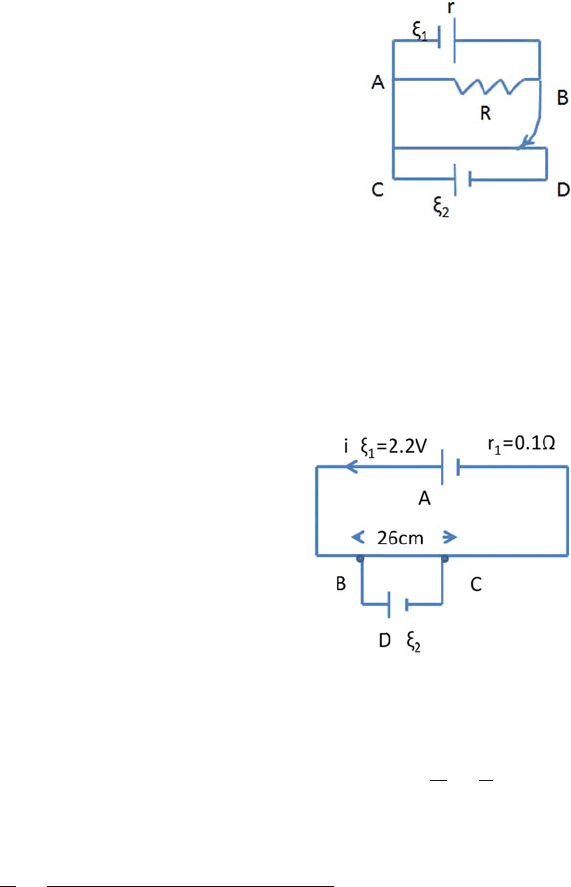
12.32 A thin uniform wire 50 cm long and of 1 resistance is connected to the
terminals of an accumulator of emf 2.2 V and the internal resistance 0.1
(Fig. 12.17). If the terminals of another cell can be connected to two points
26 cm apart on the wire without altering the current in the wire, what is the
emf of the cell?
[Northern Universities of UK]
Fig. 12.17
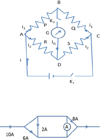
12.33 In a Wheatstone bridge, four resistors P, Q, R and S are arranged as in
Fig. 12.18. Show that
(a) condition for null deflection in the galvanometer G is
P
Q
=
R
S
(b) if a non-zero current i
g
flows through the galvanometer then
i
g
i
=
QR − PS
G(Q + S) + (P + R)(G + Q + S)
546 12 Electric Circuits
Fig. 12.18
12.34 Figure 12.19 shows a network carrying various currents. Find the current
through the ammeter A.
Fig. 12.19
12.35 A galvanometer together with an unknown resistance in series is connected
across two identical batteries, each of 1.5 V. When the batteries are connected
in series, the galvanometer records a current of 1 A and when the batteries are
in parallel the current is 0.6 A. What is the internal resistance of the battery?
[Indian Institute of Technology 1973]
12.36 In a potentiometer experiment, it is found that no current passes through the
galvanometer when the terminals of the cell are connected across 52 cm of
the potentiometer wire. If the cell is shunted by a resistance of 5 , a balance
is found when the cell is connected across 40 cm of the wire. Find the internal
resistance of the cell.
12.37 A potentiometer wire of length 100 cm has a resistance of 10 . It is con-
nected in series with a resistance and cell of emf 2 V and of negligible inter-
nal resistance. A source of emf 10 mV is balanced against a length of 40 cm
of the potentiometer wire. What is the value of the external resistance?
[Indian Institute of Technology 1976]
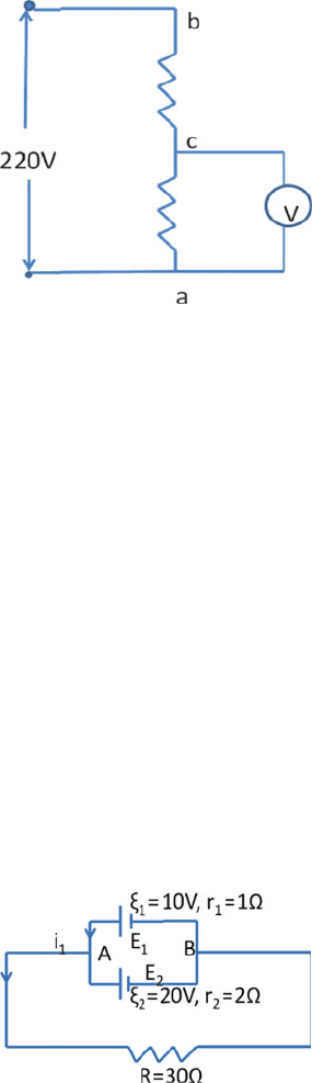
12.38 A potential difference of 220 V is maintained across a 12,000 rheostat ab
(see Fig. 12.20). The voltmeter V has a resistance of 6000 and point c is at
one-fourth the distance from a to b. What is the reading in the voltmeter?
[Indian Institute of Technology 1977]
12.39 The balance point in a meter bridge experiment is obtained at 30 cm from the
left. If the right-hand gap contains resistance of 3.5 , what is the value of
the resistance in the left-hand gap?
12.2 Problems 547
Fig. 12.20
12.2.4 Kirchhoff’s Laws
12.40 A moving coil meter has a full scale reading of 1 mA and a resistance of
80 . How could the meter be used to measure (a) 100 mA full scale and
(b) 80 V full scale?
[University of Manchester]
12.41 A pocket voltmeter has a resistance of 120 . What will it read when con-
nected to a battery of emf 9 V and an internal resistance 15 ?
[University of Oxford]
12.42 When a galvanometer is shunted with a 1 resistance, only 1% of the main
current passes through it. What is the resistance of the galvanometer?
12.43 A 10 V battery, having an internal resistance of 1.0 , is joined in parallel
with another of 20 V and internal resistance of 2 . Calculate the current
flowing through each battery, and the rates of expenditure of energy in the
two batteries and the 30 resistance (Fig. 12.21).
[University of Cambridge]
Fig. 12.21
12.44 A battery of emf 1 V and internal resistance 2 is connected to another
battery of emf 2 V and internal resistance 1 in parallel with an external
resistance of 10 . Find the currents?
548 12 Electric Circuits
12.45 The electric current of 5 A is divided into three branches, forming a parallel
combination. The lengths of the wire in the three branches are i n the ratio 2,
3 and 4; their diameters are in the ratio 3, 4 and 5. Find the current in each
branch, if the wires are of the same material.
[Indian Institute of Technology 1975]
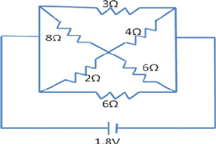
12.46 Calculate the current through the 3 resistor and the power dissipated in the
entire circuit shown in Fig. 12.22. The emf of the battery is 1.8 V and its
internal resistance is 2/3 .
[Indian Institute of Technology 1971]
Fig. 12.22
12.47 A series circuit is made up of two cells of emf 1.5 and 3 V, respectively, and
two coils each of resistance 10 , arranged in the order cell, coil, cell, coil.
The centre points of the two coils are joined by a sensitive galvanometer
which shows no deflection. If the cell of 1.5 V has an internal resistance of
5 , calculate the internal resistance of the other cell.
[University of London]
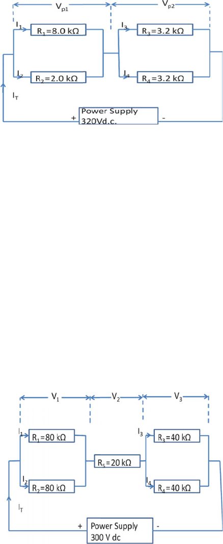
12.48
(a) Figure 12.23 shows a series parallel resistive circuit connected to a 320 V
d.c. supply. For the circuit shown work out the following:
(i) The total equivalent resistance R
T
of the circuit and the total current
I
T
.
(ii) The voltage V
p1
across resistors R
1
and R
2
.
(iii) The voltage V
p2
across resistors R
3
and R
4
.
(iv) The currents I
1
and I
3
.
(v) The total power for the whole circuit and the power dissipated in
resistor R
3
.
(b) Consider the case of a heavy duty battery whose emf ξ = 24 V and
internal resistance of r = 0.01 . If the terminals were accidentally
short circuited by a heavy copper bar of negligible resistance what power
would be dissipated within the battery?
[University of Aberystwyth, Wales 2005]
12.2 Problems 549
Fig. 12.23
12.49 A battery with emf ξ = 24 V has internal resistance r = 0.02 . A load
resistor R = 140 is connected to the terminals of a battery:
(i) Find the current flowing in the circuit under load conditions.
(ii) Find the terminal voltage of the battery under load conditions.
(iii) Find the power dissipated in the resistor R and in the battery’s internal
resistance r.
(iv) Find the open circuit voltage of the battery under no load conditions
and explain your answer.
12.50 Figure 12.24 shows a series parallel resistive circuit connected to a dc supply.
(i) Find the total equivalent resistance of the circuit.
(ii) Find currents I
T
, I
1
and I
3
.
(iii) Find voltages V
1
, V
2
and V
3
.
(iv) Find power dissipated in resistor R
5
and the total power dissipated in
the circuit.
Fig. 12.24