Jones D.S.J., Pujado P.R. Handbook of Petroleum Processing
Подождите немного. Документ загружается.

1136 CHAPTER 19
r
Natural pollution by surface run-off rainwater, or melting snow, in the form of
soluble salts leached from the earth.
r
Natural pollution caused by decay of organic plants from swamps or other sources.
r
Human and animal life excretion.
r
Chemical pollution from reducing agents in industrial plant wastes. Such as sulfides,
nitrites, ferrous salts, etc.
r
Biochemical pollution from such industrial wastes as phenols, hydrocarbons, car-
bohydrates, and the like.
The degree of oxygen depletion from the pollution sources described above may be
catalogued by the following terms:
BOD—Biological Oxygen Demand
COD—Chemical Oxygen Demand
IOD—Immediate Oxygen Demand
BOD. Since all natural waterways will contain bacteria and nutrients; almost any
waste compound introduced into the waterways will initiate biochemical reactions.
These reactions will consume some of the dissolved oxygen in the water.
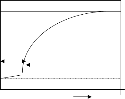
The depletion of oxygen due to biological pollution is not very rapid. It follows the
laws of first order reaction. Because of this, the effect of BOD is measured in the
laboratory on a five day basis, and has been universally adopted as the measure of
pollution effect. The “Ultimate”BOD is a measure of the total oxygen consumed
when the biological reaction proceeds to almost completion. The “5 day”BOD is
believed to be approximately the Ultimate.
In summary, BOD measures organic wastes which are biologically oxidizable.
Ultimate BOD
BOD Curve
BOD
Inactive
5 day BOD.
100
0
Time Days

A DICTIONARY OF TERMS AND EXPRESSIONS 1137
COD. The COD is a measure of the oxygen depletion due to organic and inorganic
wastes which are chemically oxidizable. There are several laboratory methods ac-
cepted to measure the oxygen depletion effect of these pollution. The two most widely
accepted are the “4 hour Permanganate”method or the “2 hour Dichromate”method.
Although there is no generalized correlation between BOD and COD, usually the
COD will be larger than the BOD. The following table illustrates how different wastes
exhibit a different relationship between COD and BOD.
COD
Source Pollutants BOD “5day” “2 hr dichromate”
Brewery Carbohydrates Proteins 550 –
Coal gas Phenols, Cyanides Thiocyanates Thio
sulphates
6,500 16,400
Laundry Carbohydrates Soaps 1,600 2,700
Pulp mill Carbohydrates Lignins, Sulfates 25,000 76,000
Domestic sewage Solids, Oil, and Grease, Proteins
Carbohydrates
350 300
Petroleum refinery
(Sour water)
Phenols Hydrocarbons Sulfides 850 1,500
Petroleum refinery Phenols, Sulfides Hydrocarbons,
Mercaptans, Chlorides
125 2,600
IOD. Oxygen consumption by reducing chemicals such as sulfides and nitrates is
typified as follows:
S
−−
+ 2O
2
→ SO
−
4
−
NO
−
2
+
1
2
O
2
→ NO
−
3
These types of inorganic oxidation reactions are very rapid and create what is measured
in the laboratory as immediate oxygen demand. If waste contaminants contain these
inorganic oxidizers, the “5 day”BOD test will include the consumption of the oxygen
due to IOD also. A separate test to determine IOD must be made and this result
subtracted from the “5 day”BOD to arrive at the true BOD result.
Toxic pollutants common to oil refining. Toxic pollutants that are most commonly
contained in untreated refinery aqueous wastes are:
Oil. Heavy oil and other hydrocarbons are the most problematic pollution to be found
in refinery water effluent. All refineries exercise the most stringent methods to control
and remove these undesirable pollutants. Indeed in many cases the treated effluent
streams leaving the refinery may well be purer than incoming portable water used in
the processes.
1138 CHAPTER 19
Phenols. This chemical often formed in refinery processes such as catalytic and
thermal crackers, are highly toxic to aquatic life in concentrations of 1–10 ppm.
Apart from its toxicity phenols also unpleasant taste and odor to drinking water in
the range of 50–100 ppb. In concentrations of 200 ppm and more, these chemicals
can also deactivate water treatment plants such as trickle filters and activated sludge
units.
Caustic soda and derivatives. Solutions containing sodium hydroxide are used in a
number of refinery processes. Inevitably some of this chemical enters the refinery’s
waste water system. This contaminant is toxic to humans and marine life in even low
concentrations. The spent caustic (compounds leaving the process) such as sodium
sulfide is even more injurious.
Aqueous solutions of ammonium salts. The most common of these are ammonium
sulfide NH
4
SH, and ammonium chloride. Both these salts are present in effluent
water from the crude distillation unit overhead accumulator, however the sulfide salt
is present in all aqueous effluents from the cracking processes, and the hydro treaters.
Other ammonium salts are also present in hydrocracking and deep oil hydrotreating.
Acids in aqueous effluents. The most common of these are from the alkylation pro-
cesses which use either hydrofluoric acid or sulfuric acid. In some isomerization
processes, hydrochloric acid is used to promote the aluminum chloride catalyst. In
some older processes sulfur dioxide is used to remove aromatics. This effluent usually
leaves these plants as dilute sulfuric acid.
Ketones, furfural, and urea. These compounds are used in the refining of lube oils.
MEK and Urea are used in the dewaxing processes while furfural is used in the
extraction processes for finished lube oil stock. All of these compounds are toxic.
Treating refinery aqueous wastes
The treatment of aqueous wastes from oil refineries fall into three categories. These
are:
r
In-plant treatment. These are onsite processes usually sour water strippers, spent
caustic oxidizers, and spent caustic neutralizers.
r
The API separator, or similar oil/water separating device.
r
Secondary treatment, which includes chemical coagulation, activated sludge pro-
cesses, trickle filters, air flotation, and aerators.
Most energy refineries contain only the first two of the above categories. These pro-
cesses are described in detail in this Handbook.
A DICTIONARY OF TERMS AND EXPRESSIONS 1139
Effluent water treating
Sour water is usually treated in petroleum refineries by one or more of the following
processes:
r
Steam Stripping
r
Caustic/Acid Neutralization
r
Caustic Oxidization
r
Oil Removal by Settling
All three of these processes with brief description of the more uncommon processes
such as coagulation are also described fully in Chapter 14 of this Handbook. A brief
summary of these are as follows:
Sour water strippers. This is one of the most common treating processes. Its purpose
is to remove the pollutant gases included in process plant effluents. The more
common pollutants in this case are ammonia, ammonium salts, and hydrogen sulfide.
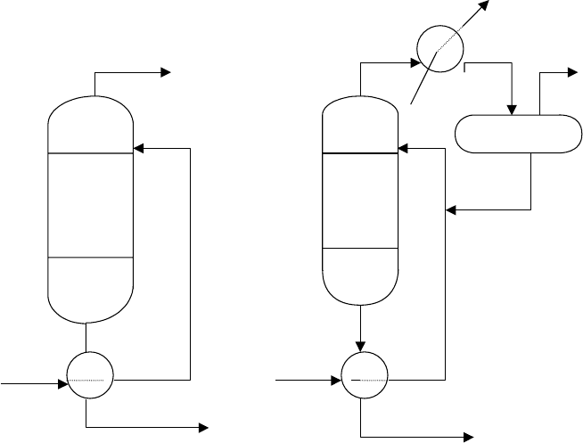
There are two types of strippers in this service; they are shown as Stripper A and B,
respectively, below:
To firebox
Reflux Drum
Top Tray Top Tray
Reflux
Bottom Tray
BottomTray
Sour Water Sour Water
Stripped Water
Stripped water
STRIPPER A STRIPPER B
1140 CHAPTER 19
Both these type of sour water stripping lend themselves to tray by tray mass and heat
transfer. The sour water feed is introduced on the top tray of the tower while steam
usually at a rates of 0.5–1.5 lbs/gallon of feed is introduced below the bottom tray.
In the case of a tower with reflux the reflux enters the tower with the fresh feed. The
design of both towers utilizes the partial pressure relationship of NH
3
and H
2
Sin
aqueous solution. These relationships are given by a series of graphs to be found in
Appendix 1 of Chapter 14.
The sour water stripper is almost always located in the process area of the refinery.
The feed to the stripper is the effluent water from the crude unit overhead conden-
ser, the water phase from the desalter, the condensed water from the vacuum unit’s
hot well, and all the water condensate from the hydro-treater product steam strip-
pers. The sour water stripper may be a single tower with no reflux as in Type A
or a single trayed tower with an overhead reflux stream (Type B). The amount of
steam used in both cases will be between 0.5 lbs steam per lb of feed to 1.5 lbs of
steam.
Spent caustic disposal. The other major effluent from oil refining is the spent caustic
streams from hydrogen sulfide removal and also the removal of phenols. Refiners usu-
ally have the following options in the disposal of these streams. In order of preference
these are listed as follows:
Phenolic spent caustic
r
Disposal by sales
r
Disposal by dumping at sea
r
Neutralizing with acid
r
Neutralizing with flue gas
Sulfidic spent caustic
r
Disposal by sales
r
Oxidation with air and steam
r
Neutralization with acid and stripping
r
Neutralization with flue gas and stripping
These processes are also described and discussed in full in Chapter 14 of this Hand-
book. A brief summary is as follows:
Neutralizing phenolic spent caustic. As listed above phenolic spent caustic can be
neutralized using acid or flue gas. When neutralized the mixture separates into two
liquid phases. The upper phase contains the acid oils while the lower phase is an
aqueous solution of sodium sulfate or sodium carbonate. The neutralization using

A DICTIONARY OF TERMS AND EXPRESSIONS 1141
either acid or flue gas can be accomplished in a batch or continuous operation. The
neutralization step is exothermic giving out around 125 Btu/lb of sprung acid. As
the objective of the process is to produce a phenol free sprung water for disposal
the system temperature should be kept as low as possible until the sprung water is
removed. Routing the sprung water to the sour water stripper ensures the removal of
any entrained H
2
S in that stream.
Spent caustic oxidation. Spent caustic cannot be steam stripped to remove the sul-
fides contained in it due to the H
2
S removal process in which the caustic was used.
This is because sodium sulfide does not hydrolyze even when heated. Acids could be
used, of course, to neutralize the spent caustic which would release gaseous H
2
S. This
would however be a costly procedure and causes a potential air pollution problem.
The alkaline sulfide can be economically oxidized to form thiosulfates and sulfates.
This is the process most commonly used in refineries where only sulfides are the
pollutants in the spent caustic and the release of gaseous H
2
S is a problem. De-
tails of this process together with a process schematic drawing are given in Chap-
ter 14.
Oil–water separation. Most aqueous effluent from a refinery will contain oil. This
oil content has to be reduced to at least 10 ppm before it can be deposited into a river,
lake, or ocean. The oil contamination sources are from process water run down, paved
area drainage, storm catch-pots, tanker ballast pump out, and tank farm diked areas.
All the water from these sources are treated in oil separation processes. The most
important of these oil–water separation process is the API Separator.
The API oil–water separator. The design of an API separator is based on the difference
in gravity of oil and water in accordance with the general laws of settling. In the design
of an API separator a modified version of Stoke’s Law is used. In this law the rate of
settling is given by the equation:
Vr = 6.69 × 10
4
d
2
S
η
where
Vr = Rising rate of the oil phase in ft/min
d = Droplet diameter in ins.
S = Difference in specific gravity of the phases.
η = Viscosity of the continuous phase (water) in centipoises.
1142 CHAPTER 19
The above modified Stoke’s Law for the API separator recognizes that the continuous
phase is water and the lighter oil phase is the one that is separated to be disposed as
the product skimmed from the surface.
An example of the application of the equation in the design of an API separator is
given in Chapter 14 Appendix 14.3 of this Handbook.
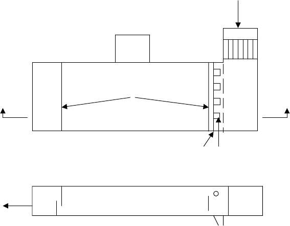
The oil phase from the separator is removed using specially designed skim pipes and
an oil sump. A simplified diagram of a typical API Separator is given below.
Waste Water Feed
Oil Sump
Trash
Screen
Distribution
Baffle
Retention Baffles
AA
Oil Skimmer Sludge Sumps
Plan View,
Side View Through A-A
A process description of the separator together with its ancillary equipment is given
in Chapter 14.
Storm surge ponds. These ponds are installed to provide storage for maximum rainfall
conditions. There are several forms of these surge ponds, some requiring pumps, some
located upstream of the API separator, and some downstream of the separator. In most
cases, the storm drain system is directed to the storm surge pond. Thus in a storm,
the excess rainfall is held in this pond and fed to the API separator, over a period of
time and at a rate that will not exceed the separator’s capability to handle the water
effectively. In this way, the refinery ensures that any oily water will not by-pass the
separator under the worst condition. The size of the surge pond must be able to handle
A DICTIONARY OF TERMS AND EXPRESSIONS 1143
the maximum rainfall and the flow from all catch basins and open culverts that form
part of the refinery drainage system.
Other refinery water effluent treatment processes. These are summarized below, but
are described more fully in Chapter 14.
Oxidation ponds. Oxidation ponds are usually used as a secondary effluent clean up
after the API separator. There are three types of these ponds which are:
r
Aerobic—Where the oxidation of the water utilizes oxygen from the atmosphere
plus oxygen produced by photosynthesis.
r
Anaerobic—Where oxidation of the wastes does not utilize oxygen.
r
Aerated—Where oxidation of the wastes utilizes oxygen introduced from the at-
mosphere by mechanical aeration.
The processes described above are those met with in oil refining most often. Indeed
of the processes described above most refineries only use the API separator and the
surge ponds to meet the oil/water separation required.
Air flotation. The purpose of the air flotation process is the clarification of waste water
by the removal of suspended solids and oil. This is achieved by dissolving air in waste
water under pressure, and then releasing it at atmospheric pressure. The released air
forms bubbles which adhere to the solid matter and oil in the waste water. The bubbles
cause the adhered matter to float in the froth on the surface of the water bulk. The
dissolved air in the water also achieves a reduction in the BOD of the effluent stream.
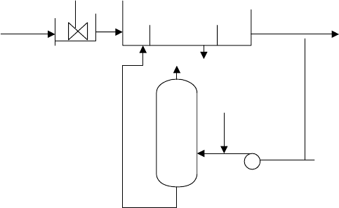
The figure below shows the principal of a typical air flotation process.
Mixing chamber Flotation Vessel
Waste water
Clean Water
Sludge
Air Drum
Aerated Water Compressed Air
Recycle Water
A typical Air Flotation Process
These processes are also described and discussed more fully in Chapter 14.
1144 CHAPTER 19
End points
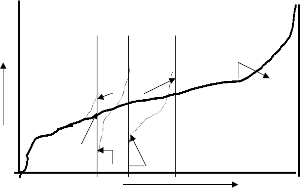
Whereas a cut point is an ideal temperature on a TBP curve to define the yield of a
fraction, the end points define the shape of the fraction when produced commercially.
In actual process, the initial boiling point of a fraction will be much lower than its front
end cut point. The final fraction boiling point will be higher than the corresponding
cut point. This is demonstrated by the figure below:
Gas Oils
Kero
Crude Oil TBP
End Points
Full range Naphtha
Temp
Cut Point
Residue
End Point
% Distilled
There is a correlation between the TBP cut point and the ASTM end point. This
is described in Chapter 1 of this Handbook. A relationship also exists for the 90%
ASTM point and the TBP 90% cut point. With these two ASTM data and using an
ASTM probability graph (see Chapter 1) a full ASTM curve with its end points can
be drawn. This converted to a TBP curve is used to define the cut’s properties.
Engineering flow diagrams
Diagrams are used extensively by all disciplines of engineers to convey ideas and
data.
Process engineers use and in some cases develop three types of flow diagrams to
project their work and responsibilities.
These are:
r
The Process Flow Diagram
r
The Mechanical Flow Diagram (sometimes called the P&I Diagram)
r
The Utilities Diagram
A DICTIONARY OF TERMS AND EXPRESSIONS 1145
The process flow diagram is always originated by the process engineer and he retains
sole responsibility for its future development and update. The Mechanical flow dia-
gram may also be initiated by the process engineer or it may be developed by others
from the process flow diagram. In many companies, however, the process engineer
remains responsible for its technical content, development, and its completeness. The
utilities diagram shows the routing, sizing, and specification of all the utility flow
lines between units and within units of a process. This diagram is usually superim-
posed on the plot layout diagram. The piping engineers or those engineers who are
responsible for initiating the plot plan drawing usually initiate the utilities drawing
and administer it. The process engineer in this case is responsible for sizing the flow
lines, establishing flow conditions of temperature and pressure, and for ensuring that
all lines have been included.
The process flow diagram
This diagram is usually the first drawing that will be produced for an engineering
or development project. In some cases, it may be preceded by a process block flow
diagram but it is the process flow diagram that is the basis for:
r
A process definition
r
A budget cost estimate
r
An equipment list
r
A mechanical flow diagram
r
Process equipment data sheets
The flow diagram supports the material and energy balances for the process and es-
tablishes the sequence and direction of the process flow. The diagram also shows
the control philosophy that will be adopted for the process and the salient temper-
ature/pressure conditions within the process. As a minimum therefore process flow
diagrams should contain the following:
Vessels. The outlines of all major vessels, such as towers, drums, tanks are shown.
Their equipment item number and their overall dimensions are indicated on the dia-
gram. Where vessels contain special internals, such as trays, demisters, packing, etc
these too should be simply indicated on the vessel drawing. For example, the number
of trays in a tower may be indicted by showing the top, feed, and bottom trays only
but including their respective tray numbers. The main temperature and pressure con-
ditions are also shown on the vessel drawing. For example on fractionation towers the
tower top and bottom operating temperatures will be shown but only the top pressure
is normally shown.
Heat exchangers. All heat exchangers are shown as single shells on the process flow
diagram. That is, no attempt is made to show the number of passes or the type (i.e.,
shell & tube, or double pipe, etc.) on this diagram. The process flows to and from these
