Ishihara T. (Ed.) Perovskite Oxide for Solid Oxide Fuel Cells (Fuel Cells and Hydrogen Energy)
Подождите немного. Документ загружается.


oxides are found to be suitable and widely used as cathode materials in a range
of intermediate- to high-temperature fuel cells.
9.2.3.1 Strontium-Doped Samarium Cobaltite
Strontium-doped samarium cobaltite (SSC) is selected as the air electrode
material of our standard cells. The slurry of Sm
0.5
Sr
0.5
CoO
3–d
powder is screen
printed onto the electrolyte disk with an already sintered anode. The final
sintering of the cathode is performed in air at a temperature range of
10008–12008C for 3 h. The average thickness of the porous cathode is about
30–50 mm. Figure 9.3(b) shows the electron microscope imag e of the air-fired
microstructure of the air electrode of our standard cell. It has been demon-
strated that the cathodic overpotential of the cell is very small [16].
9.2.3.2 Lanthanum-Doped Bar ium Cobaltite
The A site of barium cobaltite (BaCoO
3
) is partially substituted by lanthanum
ions to improve the catalytic and electrical properties of this particular oxide.
We have performed a series of performance measurements by varying the
lanthanum content between 30 at% and 50 at% and determined the optimal
value as 50 at%, that is, an equal amount to the barium content on the A site of
the barium cobaltite. Figure 9.5 shows a comparison between I-V-P character-
istics of cells made up of two different cathode materials, namely,
Ba
0.5
La
0.5
CoO
3–d
(BLC) and SSC measured at 7508C using pure hydrogen as
fuel. It is found that the cells made up of the BLC cathode have a very similar
performance to those utilizing SSC as a cathode material [17].
0
0.2
0.4
0.6
0.8
1
1.2
0 0.1 0.2 0.3 0.4 0.5 0.6 0.7
Current Density (A/cm
2
)
Terminal Voltage (V)
0
0.1
0.2
0.3
0.4
0.5
0.6
Power Density (W/cm
2
)
BLC
SSC
Fig. 9.5 I-V-P
characteristics of single cells
using strontium-doped
samarium cobaltite (SSC)
and Ba
1–x
La
x
CoO
3–d
(BLC)
as cathode
9 Intermediate-Temperature Solid Oxide Fuel Cells Using LaGaO
3
189

9.3 Stack Development
In fuel cells, as in batteries, electrochemicall y active cells should be electrically
connected in series to produce usable power. Stacking is the term most com-
monly used for connecting cells in electrical series for fuel cells. Bas ically, the
stack de sign addresses the delivery of gaseous species to the cells together with
loss-free collection of the electrical current and management of heat. These, in
principle, have direct influence on the electrochemical performances of the
individual cells. Successful heat management, on the other hand, is critically
important for the structural integrity of the components used in a stack
assembly.
Compared to alternative s tacking configurations proposed for planar cells,
interconnecting cells without the need for using seals offer a great deal of
simplicity [18]. Our disk-type cell stacking concept exploits the sealless design
concept and consists of a number of repeat units, each of which is made up of
only cells, porous current collectors, and metallic separators. F igure 9.6
illustrates the conceptual drawing of the single cell stack unit. Air and fuel
gas are supplied to the unit through the channels inside the s eparators. The
openings at the center of separators serve as gas inlets to the porous current
collectors. The uniform flow regimen of gas along the radial direction over the
electrodes is maintained by t he help of the porous current collectors. The
thicknesses and the porosity values of the current collectors are carefully
optimized to obtain the highest rates of axial diffusion of gases. Ferritic
stainless steel is used as a material for the separator plates. As there are no
circumferential seals attached to the cells, the unutilized fuel and depleted air
are freely mixed and burned around the stack unit. The combustion heat is
further utilized for the heat management of the entire stack and the balance of
plant c omponents around it (steam genera tor, pre-reformer, and heat exchan-
gers, etc.).
Figure 9.7 shows the actua l cell stack unit assembly for the fourth-
gene ration 1- kW c lass module. The individual s eparator plates are designed
Metallic separator
Porous current collector
Cathode
Electrolyte
Anode
Air
Fuel
Fig. 9.6 Conceptual
illustration for the sealless
stack unit
190 T. Akbay
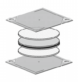
by using a rather unique concept of internal gas manifolding. Holes on
opposite corners serve as gas manifolds when separator plates are stacke d
by placi ng ceramic rings over them. Inne r gas channels in the separ ator
plate connect the gas manifolds to two openi ngs located at the center of
opposite sides of the separator. The fuel gas supplied from the central
opening flows through the anode-side current coll ector and undergoes
internal steam reforming and anode electr ode reaction. Meanwhile, the air
supplied from the opening on the opposite side of the separator flows
through the cathode-side current collector and takes part in the cathode
electrode reaction.
Apart from supplying gases to the cells and serving as e lectrical connec-
tion between individual cells, the separator plate in our stack design has an
additional functionality for isolating the compressive forces on the disk-
type cells placed at their center and the ceramic rings use d for the gas
manifolds. This unique functionality is accomplished by attaching flexible
arms to the separator plates. The manifold ends of the separator arms and
ceramic rings must be tightened by bolts and nuts to make hermetic seals.
On the other hand, the interconnec tion parts of the separators where cells
and current collectors are placed require certain levels of pressure to mini-
mize electric contact resistance between them. The milder load requirement
on the interconnection parts is mainly exerted by a wei ght at the top of the
cell stack.
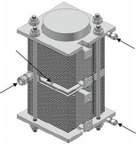
The fourth- gener ation 1-kW cla ss stack s hown in Fig. 9.8 consists of
46 cells connected in electrical series. Electrically insulated clear hole
flanges are attac hed to the extreme ends of the stack and tightened by
using st ud bolts to fixate the entire assembly. The air inlet for the stack is
attached to the air manifold at the mid-height of the stack while the fuel
inlets are attached to top and bottom flang es that have built-in openi ngs to
the fuel manifolds. To enhance the heat exchange between the stack and
balance of plant components, an additional ra diator plate is insert ed at the
mid- height of the stack.
Porous current collector (air)
Cathode/Electrolyte/Anode
Porous current collector (fuel)
Metallic separator
Metallic separator
Fig. 9.7 Cell stack unit
assembly for the fourth-
generation 1-kW class
module
9 Intermediate-Temperature Solid Oxide Fuel Cells Using LaGaO
3
191
9.4 Module Development
The previously mentioned sealless stacking concept is highly pertinent to elec-
trical power scaling by means of altering the number of cells. In other words, the
number of cells can easily be increased for higher power output per stack.
However, there is an intrinsic limit for the maximum number of standard-
sized (120 mm in diameter) cells that can actually be stacked due to the very
nature of the sealless stacking design. As can be imagined, the larger the number
of cells, the taller the stack, which exerts its own weight as increased amount of
pressure on the porous current colle ctors and cells toward the bottom of the
stack. To eliminate a possible mechanical failure in cells, we have decided to
build a generic-sized stack to be connected electrically in series for manufactur-
ing larger-sized SOFC power production units.
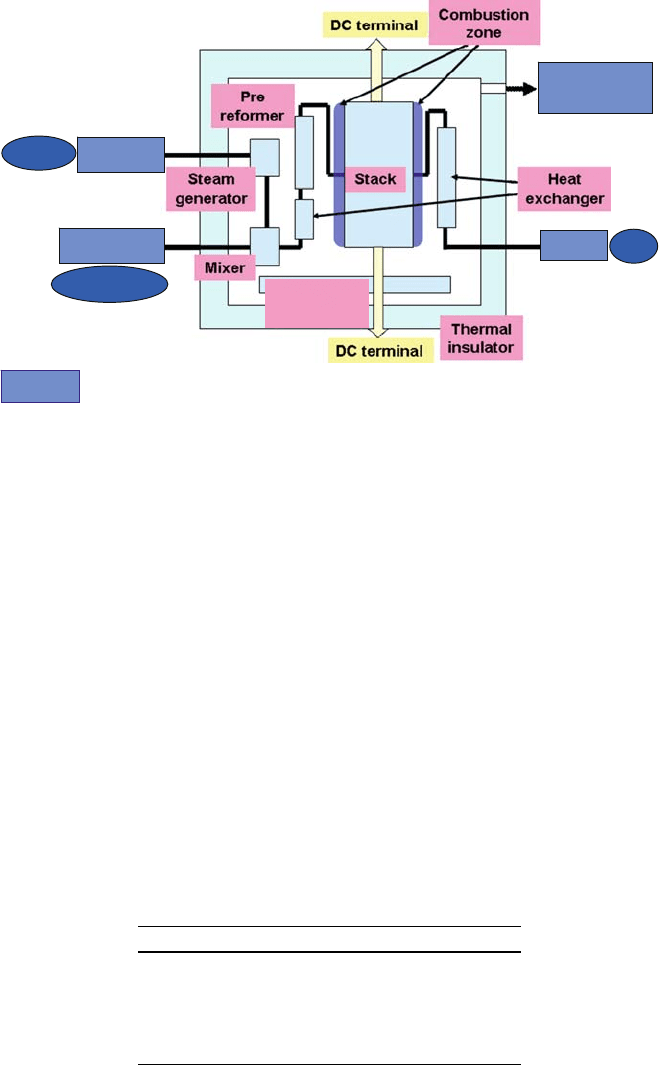
As illu strated in Fig. 9.9, we often use the term module for a DC power
generation unit composed of generic SOFC stack(s) together with all the rest of
the hot balance of plant components efficiently packed inside a thermally
insulated lining. The module utilizes desulfurized town gas and deionized
water for internal steam reforming. Air is preheated before entering to the
stack. The relative positions of the components inside the module are carefully
designed for optimal heat management.
9.4.1 A 1-kW Class Single-Stack Module
Single-stack modules capable of generating around 1 kW electrical power out-
put have been developed as test platforms and continuously evolved up to the
current design, named the fourth generat ion. In all generations, the internal
steam reforming concept is adopted for thermally self-sustained operation,
except for the first-generation module, which is designed for hydrogen fuel. In
each design iteration, the SOFC stack together with the balance of plant
Fuel inlet
Air inlet
Radiator plates
Fuel inlet
Fig. 9.8 CAD
representation of the fourth-
generation 1-kW class
SOFC stack
192 T. Akbay
components is optimized for obtaining higher electrical conversion efficiencies
and long-term stability.
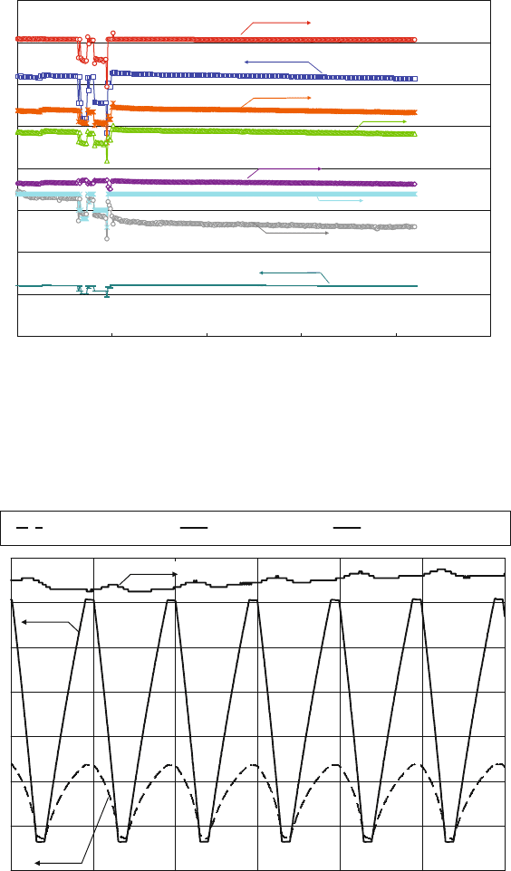
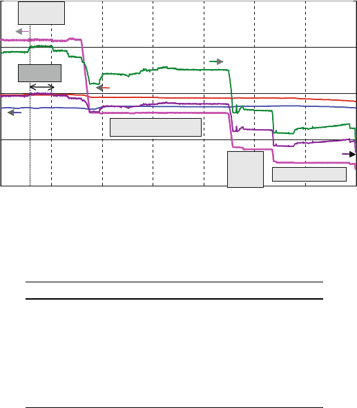
A constant power output durability test of the fourth-generation 1-kW class
module is performed over 4200 h. The operating conditions are listed in Table 9.1.
The data recorded during the entire test period are plotted as a graph (shown in
Fig. 9.10). The operation was interrupted briefly at 1000 h to correct the erratic
behavior of the stack that started around 600 h. After the restart, the remaining
period of operation was trouble free. The electrical efficiency remained about
50% Higher Heating Value (HHV) throughout the test. The voltage degradation
after the restart was calculated as 0.5% per 1000 h.
A cyclic power output durability test is also conducted for more than 1000
cycles. The DC power output of the stack is alternately cycled between 100%
and 10% for the frequency of 6 cycles per hour (Fig. 9.11). The stack behavior
was rather stable, while the degradation rate for certain cells was slightly higher
than the constant power output test case.
Blower
Air
Water
Town gas
: BoP component
Burner or
Elect. heater
Exhaust heat
recovery unit
Deionizer
Desulfurizer
Fig. 9.9 Concept of the module
Table 9.1 Operating conditions for the durability test
of the fourth-generation 1-kW module
Fuel Town gas (13 A)
Total current 33.9 A
Current density 0.3 A/cm
2
Fuel utilization 71%
S/C 3.0
Maximum separator temperature 7908C
9 Intermediate-Temperature Solid Oxide Fuel Cells Using LaGaO
3
193
0
200
400
600
800
1000
1200
1400
1600
0 1000 2000 3000 4000 5000
Time (h)
Output Power (W), Power density(mW/cm
2
)
0
10
20
30
40
50
60
70
80
Electrical
Efficiency[LHV,HHV] (%),
Fuel
Uti
l
i
zati on (%),
Air Utilization (%),
Termainal Volta
g
e(V), Current (A)
Fuel Utilization (fixed)
Output Power
Electrical Efficiency [LHV]
Electrical Eficiency [HHV]
Terminal Voltage
Current (fixed)
Air Utilization
Power Density
Fig. 9.10 1-kW module durability test over 4200 h
0
20
40
60
80
100
120
140
8:20:00 8:30:00 8:40:00 8:50:00 9:00:00 9:10:00 9:20:00
Time
Output power [W × 0.1], Efficiency [%]
660
680
700
720
740
760
780
800
Tem
p
erature [°C ]
Efficiency (HHV)
Output Power Maximum Temperature
Maximum Temperature
Output power
Efficiency
Fig. 9.11 Cyclic durability test results for the 1-kW module
194 T. Akbay
9.4.2 A 10-kW Class Multi-Stack Module
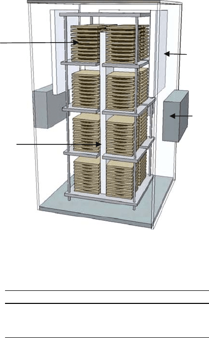
Figure 9.12 depicts the conceptual drawing of the 10-kW class intermediate-
temperature SOFC module. The outer dimensions of the module are about 1 m
(W) 1 m (D) 2 m (H). A three- dimensional array of 16 generic stacks (2
2 4) that are connected electrically in series is used to produce the output
power of 12.6 kW DC with a gross electrical efficiency of 50% (HHV) at an
operation temperature below 8008C. A flat-plate box-type steam reformer is
designed and positioned vertically between the stacks to keep its temperature as
high as possible. Fuel gas and air streams introduced to the module are passed
through dedicated plate-type heat exchangers before being distributed to the
SOFC stacks in the array. Start -up burners that utilize town gas are positioned
inside the insulator linings near the stacks to heat up the module. Table 9.2
summarizes the design specifications of the 10-kW class module.
Start-up burner
Heat exchanger
Cell stack
Reformer
Fig. 9.12 Conceptual view of a 10-kW class module
Table 9.2 Specifications of the 10-kW class module
Fuel Town gas (13 A)
Output power 12.6 kW DC
Electrical efficiency 50% HHV
Maximum separator temperature <8008C
9 Intermediate-Temperature Solid Oxide Fuel Cells Using LaGaO
3
195
A short-term performance test demonstrated that the 10-kW class module is
capable of meeting the design specifications for full load and partial load opera-
tions. Figure 9.13 shows the various data recorded during the test. The DC power
output of 12.7 kW is obtained under full load operation at 76% fuel utilization,
analogous to the electrical efficiency of 50% HHV. The operational character-
istics during the thermally self-sustained operation are listed in Table 9.3.
9.5 System Development
While demonstrating the 10-kW class module capability in meeting the DC
target specifications, a combined heat and power (CHP) system is developed for
utilizing the module within a co mplete system configuration [19, 20]. The
photograph shown in Fig. 9.14 is for the actual 10-kW class CHP system
installed at Rokko Testing facilities of The Kansai Electr ic Power Co., Inc.
The system consists of a 10-kW class SOFC module, a unit for gas and water
supply equipment, a unit for power electronics, a control unit, and an exhaust
heat recovery unit.
0
400
800
1200
1600
06:00 12:00 18:00 00:00 06:00 12:00 18:00 00:00
25
50
75
100
Partial load : 6.3kW
Partial
load:
3.2kW
Partial load : 2.0kW
50 HHV
Full load
12.7kW
Stack min.
temperature
Fuel utilization
Output power (DC)
Electrical
efficiency
0
400
800
1200
1600
06:00 12:00 18:00 00:00 06:00 12:00 18:00 00:00
Time
0
25
50
75
100
Electrical efficiency (%HHV)
Fuel utilization (%)
Partial load : 6.3kW
Partial
load:
3.2kW
Partial load : 2.0kW
50%HHV
Full load
12.7kW
Stack max. temperature
Stack min.
temperature
Fuel utilization
Output power (DC)
Electrical
efficiency
Output power (× 10W)
Stack temperature (°C)
Fig. 9.13 Operation data of the first 10-kW class module
Table 9.3 Typical performance of the 10-kW class module
DC output power (kW) 12.7
Average area-specific power density (W/cm
2
) 0.208
DC terminal voltage (V) 415
Efficiency at DC terminal (%HHV) 50
Fuel utilization (%) 76
Air utilization (%) 53
Average cell voltage (V) 0.77
Stack temperature (8C) 675–787
196 T. Akbay

The control unit of the system is specifically designed for automated start-up,
power generation, hot-standby, and scheduled or emergency shut-down pro-
cesses. For the power electronics, a DC/AC inverter is attached to the module
for grid connection. The heat recovery unit is attached to the module’s exhau st
to generate hot water at a temperature between 608 and 908C. The volumetric
capacity of the hot water tank is selected as 370 liters with a suitably sized water
pump. The condensed water recycling unit is attached to the system for possible
utilization of pure water for internal steam reforming.
An initial performance test is performed on the system to validate the design
specifications. The test results are summarized in Table 9.4. The AC power
output of the system is obtained as 10.1 kW wi th a corresponding AC electrical
conversion efficiency of 41% HHV. The overall syst em efficiency, on the other
hand, is recorded as 82% HHV when the module exhaust heat is recovered as
hot water at 608C. These results clearly demonstrate that an intermediate-
temperature SOFC CHP system of this size is perfectly capable of generating
electric power as well as quality heat with high efficiency figures.
Figure 9.15 shows the data obtained during the long-term stability test per-
formed over an accumulated period of 3400 h. The system is stably operated during
2.35m
SOFC
module
DC/AC
inverter
Heat
recovery
unit
Control
unit
2m1.5m
Fig. 9.14 The 10-kW class CHP system
Table 9.4 Test results of the 10-kW CHP system
Fuel Town gas (13 A)
AC output power 10.1 kW
AC electrical efficiency 41% HHV
Overall efficiency
a
82% HHV
Maximum separator temperature 7768C
CHP, combined heat and power.
a
Exhaust heat is recovered as hot water at 608C.
9 Intermediate-Temperature Solid Oxide Fuel Cells Using LaGaO
3
197

the comprehensive portion of the test period except for some unexpected electrical
trips caused by malfunctioning gas flow controllers and temperature sensing
system. The fluctuation in the overall system efficiency is attributed to a lag
between the heat recovery control and the module’s inlet water flow rate control.
9.6 Stack Modeling
As numerous parameters affect the operational characteristics of fuel cells, the
search for an optimum combination can be very difficult. In this respect, a
mathematical modeling app roach is widely used in fuel cell research and devel-
opment to perform various analyses ranging from estimation to design itera-
tion. Predictive models, however, are only useful when they are verified by
experimental evidence.
Among various levels of modeling, particular attention is paid to the cell and
stack models for supporting our stack development. In this section, the discus-
sion is be restricted to a standard computational fluid dynamics (CFD) analysis
coupled with rigorous elect rochemistry of the generic 34-cell stack. The stan-
dard approach includes solving the governing equations of mass and momen-
tum conservation (Navier–Stokes) together with energy, species, and charge
transport phenomena. Chemical and electrochemical reaction kinetics are also
included to evaluat e necessary source or sink terms for the transport equations.
A commercially available CFD package is used for solving the coupled set of
transport equations [21]. Detailed explanation of the multiphysics model, which
is out side the scope of this section, may be found elsewhere [22, 23].
0
10
20
30
40
50
60
70
80
90
0
100
200
300
400
500
600
700
800
900
Average Stack Temperature (°C), Voltage (V)
Overall Efficiency
AC Output Power
AC Efficiency
DC Output Power
DC Current
DC Voltage
DC Efficiency
Fuel Utilization
Ave. Stack Temp.
srh915srh055srh492srh7361
Output Power (kW), Efficiency (% HHV),
Fuel Utilization (%), Current (A)
0 500 1000 1500 2000 2500 3000 3500
Time (h)
Fig. 9.15 Long-term stability test of the 10-kW CHP system
198 T. Akbay
