Hibbeler R.C. Structural Analysis
Подождите немного. Документ загружается.

150 CHAPTER 4INTERNAL LOADINGS DEVELOPED IN S TRUCTURAL MEMBERS
4
4.3 Shear and Moment Diagrams
for a Beam
If the variations of V and M as functions of x obtained in Sec. 4–2 are
plotted, the graphs are termed the shear diagram and moment diagram,
respectively. In cases where a beam is subjected to several concentrated
forces, couples, and distributed loads, plotting V and M versus x can
become quite tedious since several functions must be plotted. In this
section a simpler method for constructing these diagrams is discussed—a
method based on differential relations that exist between the load, shear,
and moment.
To derive these relations, consider the beam AD in Fig. 4–9a, which is
subjected to an arbitrary distributed loading and a series of
concentrated forces and couples. In the following discussion, the
distributed load will be considered positive when the loading acts upward
as shown. We will consider the free-body diagram for a small segment of
the beam having a length Fig. 4–9b. Since this segment has been chosen
at a point x along the beam that is not subjected to a concentrated force
or couple, any results obtained will not apply at points of concentrated
loading.The internal shear force and bending moment shown on the free-
body diagram are assumed to act in the positive direction according to the
established sign convention, Fig. 4–1. Note that both the shear force and
moment acting on the right face must be increased by a small, finite
amount in order to keep the segment in equilibrium. The distributed
loading has been replaced by a concentrated force that acts at a
fractional distance from the right end, where (For
example, if w(x) is uniform or constant, then will act at so
.) Applying the equations of equilibrium, we have
¢M = V¢x + w1x2 P1¢x2
2
-V¢x - M - w1x2 ¢x P1¢x2+ 1M +¢M2= 0d+©M
O
= 0;
¢V = w1x2 ¢x
V + w1x2 ¢x - 1V +¢V2= 0+
c
©F
y
= 0;
P=
1
2
1
2
¢x,w1x2¢x
0 6P61.P1¢x2
w1x2¢x
¢x,
w = w1x2
M
1
B C
M
2
x
x
F
1
F
2
F
3
w w(x)
w
x
D
A
(a)
x
V V
(b)
w(x)x
w(x)
M
V
M M
O
P (x)
Fig. 4–9
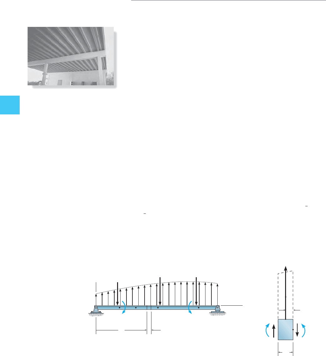
The many concentrated loadings acting
on this reinforced concrete beam create a
variation of the internal loading in the
beam. For this reason, the shear and moment
diagrams must be drawn in order to properly
design the beam.

4.3 SHEAR AND MOMENT DIAGRAMS FOR A BEAM 151
4
Dividing by and taking the limit as these equations become
(4–1)
(4–2)
As noted, Eq. 4–1 states that the slope of the shear diagram at a point
(dV兾dx) is equal to the intensity of the distributed load w(x) at the point.
Likewise, Eq. 4–2 states that the slope of the moment diagram (dM兾dx) is
equal to the intensity of the shear at the point.
Equations 4–1 and 4–2 can be “integrated” from one point to another
between concentrated forces or couples (such as from B to C in Fig. 4–9a),
in which case
(4–3)
and
(4–4)
As noted, Eq. 4–3 states that the change in the shear between any two
points on a beam equals the area under the distributed loading diagram
between the points. Likewise, Eq. 4–4 states that the change in the moment
between the two points equals the area under the shear diagram between
the points. If the areas under the load and shear diagrams are easy to
compute, Eqs. 4–3 and 4–4 provide a method for determining the numerical
values of the shear and moment at various points along a beam.
Change in
Moment
f = e
Area under
Shear Diagram
¢M =
L
V1x2 dx
Change in
Shear
f = c
Area under
Distributed Loading
Diagram
¢V =
L
w1x2 dx
Slope of
Moment Diagram
f = 5Shear
dM
dx
= V
Slope of
Shear Diagram
f = e
Intensity of
Distributed Load
dV
dx
= w1x2
¢x : 0,¢x

152 CHAPTER 4INTERNAL LOADINGS DEVELOPED IN S TRUCTURAL MEMBERS
4
From the derivation it should be noted that Eqs. 4–1 and 4–3 cannot be
used at points where a concentrated force acts, since these equations do
not account for the sudden change in shear at these points. Similarly,
because of a discontinuity of moment, Eqs. 4–2 and 4–4 cannot be used at
points where a couple moment is applied. In order to account for these
two cases, we must consider the free-body diagrams of differential
elements of the beam in Fig. 4–9a which are located at concentrated
force and couple moments. Examples of these elements are shown in
Figs. 4–10a and 4–10b, respectively. From Fig. 4–10a it is seen that force
equilibrium requires the change in shear to be
(4–5)
Thus, when F acts downward on the beam, is negative so that the shear
diagram shows a “jump” downward. Likewise, if F acts upward, the jump
is upward. From Fig. 4–10b, letting moment equilibrium
requires the change in moment to be
(4–6)
In this case, if an external couple moment is applied clockwise,
is positive, so that the moment diagram jumps upward, and when M acts
counterclockwise, the jump must be downward.1¢M2
¢M M¿
¢M = M¿d+©M
O
= 0;
¢x : 0,1¢V2
¢V
¢V =-F+
c
©F
y
= 0;
F
M
V
V V
M M
(a)
x
M¿
M
V
x
V V
(b)
M M
O
Fig. 4–10

4.3 SHEAR AND MOMENT DIAGRAMS FOR A BEAM 153
4
Procedure for Analysis
The following procedure provides a method for constructing the shear
and moment diagrams for a beam using Eqs. 4–1 through 4–6.
Support Reactions
• Determine the support reactions and resolve the forces acting on
the beam into components which are perpendicular and parallel
to the beam’s axis.
Shear Diagram
• Establish the V and x axes and plot the values of the shear at the
two ends of the beam.
• Since the slope of the shear diagram at any point is
equal to the intensity of the distributed loading at the point. (Note
that w is positive when it acts upward.)
• If a numerical value of the shear is to be determined at the point,
one can find this value either by using the method of sections as
discussed in Sec. 4–1 or by using Eq. 4–3, which states that the
change in the shear force is equal to the area under the distributed
loading diagram.
• Since w(x) is integrated to obtain V, if w(x) is a curve of degree n,
then V(x) will be a curve of degree For example, if w(x) is
uniform, V(x) will be linear.
Moment Diagram
• Establish the M and x axes and plot the values of the moment at
the ends of the beam.
• Since the slope of the moment diagram at any point
is equal to the intensity of the shear at the point.
• At the point where the shear is zero, and therefore
this may be a point of maximum or minimum moment.
• If the numerical value of the moment is to be determined at a
point, one can find this value either by using the method of
sections as discussed in Sec. 4–1 or by using Eq. 4–4, which states
that the change in the moment is equal to the area under the shear
diagram.
• Since V(x) is integrated to obtain M, if V(x) is a curve of degree n,
then M(x) will be a curve of degree For example, if V(x) is
linear, M(x) will be parabolic.
n + 1.
dM>dx = 0,
dM>dx = V,
n + 1.
dV>dx = w,

154 CHAPTER 4INTERNAL LOADINGS DEVELOPED IN S TRUCTURAL MEMBERS
4
The two horizontal members of the power line support frame are
subjected to the cable loadings shown in Fig. 4–11a. Draw the shear
and moment diagrams for each member.
SOLUTION
Support Reactions. Each pole exerts a force of 6 kN on each
member as shown on the free-body diagram.
Shear Diagram. The end points and
are plotted first, Fig. 4–11b.As indicated, the shear between
each concentrated force is constant since The shear
just to the right of point B (or C and D) can be determined by the
method of sections, Fig. 4–11d.The shear diagram can also be established
by “following the load” on the free-body diagram. Beginning at A the
4 kN load acts downward so No load acts between A
and B so the shear is constant. At B the 6 kN force acts upward, so the
shear jumps up 6 kN, from to , etc.
Moment Diagram. The moment at the end points and
is plotted first, Fig. 4–11c. The slope of the moment
diagram within each 1.5-m-long region is constant because V is
constant. Specific values of the moment, such as at C, can be deter-
mined by the method of sections, Fig. 4–11d, or by finding the change
in moment by the area under the shear diagram. For example, since
at A, then at C,
.=-3 kN
#
m+ 211.52
0 + 1-4211.52=M
C
= M
A
+¢M
AC
M
A
= 0
x = 6 m, M = 0
x = 0, M = 0
+2 kN-4 kN
V
A
=-4 kN.
w = dV>dx = 0.
V = 4 kN
x = 6 m,x = 0, V =-4 kN
EXAMPLE 4.7
6 kN6 kN
4 kN 4 kN4 kN
1.5 m 1.5 m 1.5 m 1.5 m
(c)
(b)
(a)
1.5
6 6
3
3
2
4
4.5 6
x (m)
M (kNm)
8
2
4
31.5 4.5 6
x (m)
V (kN)
ABCDE
V negative constant
M slope negative constant
V positive constant
M slope positive constant
w 0
V slope 0
w 0
V slope 0
6 kN
4 kN
1.5 m 1.5 m
(d)
V
C
M
C
Fig. 4–11

4.3 SHEAR AND MOMENT DIAGRAMS FOR A BEAM 155
4
EXAMPLE 4.8
Draw the shear and moment diagrams for the beam in Fig. 4–12a.
9 m
20 kN/m
(a)
V (kN)
30
⫺60
x (m)
(c)
5.20 m
20 kN/m
(b)
30 kN 60 kN
104
M (kN⭈ m)
x (m)
(d)
V positive decreasing
M slope positive decreasing
w negative increasing
V slope negative increasing
V negative increasing
M slope negative increasing
Fig. 4–12
SOLUTION
Support Reactions. The reactions have been calculated and are
shown on the free-body diagram of the beam, Fig. 4–12b.
Shear Diagram. The end points and
are first plotted. Note that the shear diagram starts
with zero slope since at and ends with a slope of
The point of zero shear can be found by using the method of
sections from a beam segment of length x, Fig. 4–12e.We require
so that
Moment Diagram. For the value of shear is
positive but decreasing and so the slope of the moment diagram is also
positive and decreasing At
Likewise for the shear and so the slope of the
moment diagram are negative increasing as indicated.
The maximum value of moment is at since
at this point, Fig. 4–12d. From the free-body diagram in
Fig. 4–12e we have
M = 104 kN
#
m
-3015.202+
1
2
c20a
5.20
9
bd15.202a
5.20
3
b + M = 0d +©M
S
= 0;
V = 0
dM>dx =x = 5.20 m
5.20 m 6 x 6 9 m,
dM>dx = 0.x = 5.20 m,1dM>dx = V2.
0 6 x 6 5.20 m
30 -
1
2
c20a
x
9
bdx = 0
x = 5.20 m+
c
©F
y
= 0;
V = 0,
w =-20 kN/m.
x = 0,w = 0
V =-60 kN
x = 9 m,V =+30 kNx = 0,
(e)
30 kN
[20 ( )]x
1
—
2
x
—
9
x
—
9
20 ( )
V
M
x
x
—
3

156 CHAPTER 4INTERNAL LOADINGS DEVELOPED IN S TRUCTURAL MEMBERS
4
Draw the shear and moment diagrams for the beam shown in Fig. 4–13a.
SOLUTION
Support Reactions. The reactions are calculated and indicated on
the free-body diagram.
Shear Diagram. The values of the shear at the end points A
and B are plotted. At C the shear is
discontinuous since there is a concentrated force of 600 lb there. The
value of the shear just to the right of C can be found by sectioning
the beam at this point. This yields the free-body diagram shown in
equilibrium in Fig. 4–13e. This point is plotted on the
shear diagram. Notice that no jump or discontinuity in shear occurs
at D, the point where the couple moment is applied,
Fig. 4–13b.
Moment Diagram. The moment at each end of the beam is zero,
Fig. 4–13d. The value of the moment at C can be determined by the
method of sections, Fig. 4–13e, or by finding the area under the shear
diagram between A and C. Since
Also, since the moment at D is
A jump occurs at point D due to the couple moment of
The method of sections, Fig. 4–13f, gives a value of just to
the right of D.
+2500 lb
#
ft
4000 lb
#
ft.
M
D
=-1500 lb
#
ft
M
D
= M
C
+¢M
CD
= 1000 lb
#
ft + 1-500 lb215 ft2
M
C
= 1000 lb
#
ft,
M
C
= 1000 lb
#
ft
M
C
= M
A
+¢M
AC
= 0 + 1100 lb)(10 ft)
M
A
= 0,
4000-lb
#
ft
1V =-500 lb2
1V
B
=-500 lb21V
A
=+100 lb2
EXAMPLE 4.9
10 ft
5 ft
5 ft
C
D
600 lb
4000 lb⭈ft
(a)
B
A
V negative constant
M slope negative constant
V (lb)
100
x (ft)
⫺500
(c)
10 ft 5 ft
600 lb
4000 lb⭈ft
100 lb 500 lb
(b)
5 ft
M (lb⭈ft)
2500
⫺1500
1000
(d)
x (ft)
w =0
slope =0
V
10 ft
600 lb
1000 lb⭈ft
100 lb
(e)
⫺500 lb
C
10 ft 5 ft
600 lb
100 lb
(f)
2500 lb⭈ft
⫺500 lb
4000 lb⭈ft
D
Fig. 4–13

4.3 SHEAR AND MOMENT DIAGRAMS FOR A BEAM 157
4
EXAMPLE 4.10
Draw the shear and moment diagrams for each of the beams shown in
Fig. 4–14.
SOLUTION
In each case the support reactions have been calculated and are
shown in the top figures. Following the techniques outlined in the pre-
vious examples, the shear and moment diagrams are shown under
each beam. Carefully notice how they were established, based on the
slope and moment, where and Calculated
values are found using the method of sections or finding the areas
under the load or shear diagrams.
dM>dx = V.dV>dx = w
3 m
9 kN 9 kN
6 kN/m
3 m
x (m)
x (m)
V (kN)
M (kN⭈m)
9
3
36
–9
18
(a)
w negative increasing
V slope negative increasing
V negative increasing
M slope negative increasing
4 ft
6 k/ft
15 k
8 k
47 k
4 ft
(c)
4
⫺80
⫺20
8
x (ft)
M (k⭈ft)
20 k⭈ft
⫺15
8
8
32
4
x (ft)
V (k)
V positive decreasing
M slope positive decreasing
w negative constant
V slope negative constant
3 m
30 kN
8 kN/m
1.5 m
42 kN⭈m
15 kN⭈m
15
2.64
⫺42
⫺30
⫺6
1.5
12
1.5
4.5
x (m)
x (m)
V (kN)
M (kN⭈m)
(b)
w negative increasing
V slope negative increasing
V negative increasing
M slope negative increasing
Fig. 4–14

158 CHAPTER 4INTERNAL LOADINGS DEVELOPED IN S TRUCTURAL MEMBERS
4
Fig. 4–15
The beam shown in the photo is used to support a portion of the
overhang for the entranceway of the building.The idealized model for
the beam with the load acting on it is shown in Fig. 4–15a. Assume B is
a roller and C is pinned. Draw the shear and moment diagrams for the
beam.
SOLUTION
Support Reactions. The reactions are calculated in the usual
manner.The results are shown in Fig. 4–15b.
Shear Diagram. The shear at the ends of the beam is plotted first,
i.e., and Fig. 4–15c.To find the shear to the left
of B use the method of sections for segment AB, or calculate the area
under the distributed loading diagram, i.e.,
The support reaction causes the shear to jump up
The point of zero shear can be determined
from the slope or by proportional triangles,
Notice how the V diagram follows the
negative slope, defined by the constant negative distributed loading.
Moment Diagram. The moment at the end points is plotted first,
Fig. 4–15d. The values of and 0.239 on the
moment diagram can be calculated by the method of sections, or by
finding the areas under the shear diagram. For example,
Likewise,
show that the maximum positive moment is Notice
how the M diagram is formed, by following the slope, defined by the
V diagram.
0.239 kN
#
m.
M
B
=-2.81 kN
#
m.M
B
- 0 =
1
2
1-7.50210.752=-2.81,
¢M =
-2.81M
A
= M
C
= 0,
x = 0.781 m.2.19>11 - x2,
7.81>x =-10 kN>m,
-7.50 + 15.31 = 7.81 kN.
V
B
-
=-7.50 kN.
¢V = V
B
- 0 =-1010.752,
V
C
=-2.19 kN,V
A
= 0
EXAMPLE 4.11
0.75 m
10 kN/m
1 m
A
B
C
(a)
0.75 m
10 kN/m
1 m
A
B
C
2.19 kN15.31 kN
(b)
x (m)
V (kN)
⫺7.50
⫺2.19
7.81
0.781 m
(c)
⫺2.81
0.239
x (m)
M (kN⭈m)
(
d
)

4.3 SHEAR AND MOMENT DIAGRAMS FOR A BEAM 159
4
EXAMPLE 4.12
Draw the shear and moment diagrams for the compound beam shown
in Fig. 4–16a.Assume the supports at A and C are rollers and B and E
are pin connections.
SOLUTION
Support Reactions. Once the beam segments are disconnected
from the pin at B, the support reactions can be calculated as shown in
Fig. 4–16b.
Shear Diagram. As usual, we start by plotting the end shear at A
and E, Fig. 4–16c. The shape of the V diagram is formed by following
its slope, defined by the loading. Try to establish the values of shear
using the appropriate areas under the load diagram (w curve) to find
the change in shear. The zero value for shear at can either be
found by proportional triangles, or by using statics, as was done in
Fig. 4–12e of Example 4–8.
Moment Diagram. The end moments and
are plotted first, Fig. 4–16d. Study the diagram and note how the
various curves are established using Verify the numerical
values for the peaks using statics or by calculating the appropriate
areas under the shear diagram to find the change in moment.
dM>dx = V.
M
E
= 0M
A
= 60 k
#
ft
x = 2 ft
A
BC
DE
10 ft 6 ft 4 ft 6 ft
5 k
2 k/ft
3 k/ft
60 k · ft
(a)
6 ft
20 k
5 k
3 k/ft
60 k⭈ft
4 k
16 k
16 k
0
45 k 6 k
0
(b)
V (k)
4
2
10 16 20
⫺16
⫺21
24
6
32
x (ft)
(c)
M (k⭈ ft)
64
60
2
10 16 20
⫺96
⫺180
32
x (ft)
(d)
Fig. 4–16