Hibbeler R.C. Structural Analysis
Подождите немного. Документ загружается.

120 CHAPTER 3ANALYSIS OF STATICALLY DETERMINATE TRUSSES
3
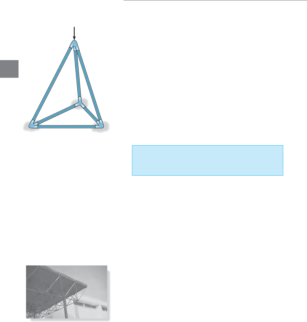
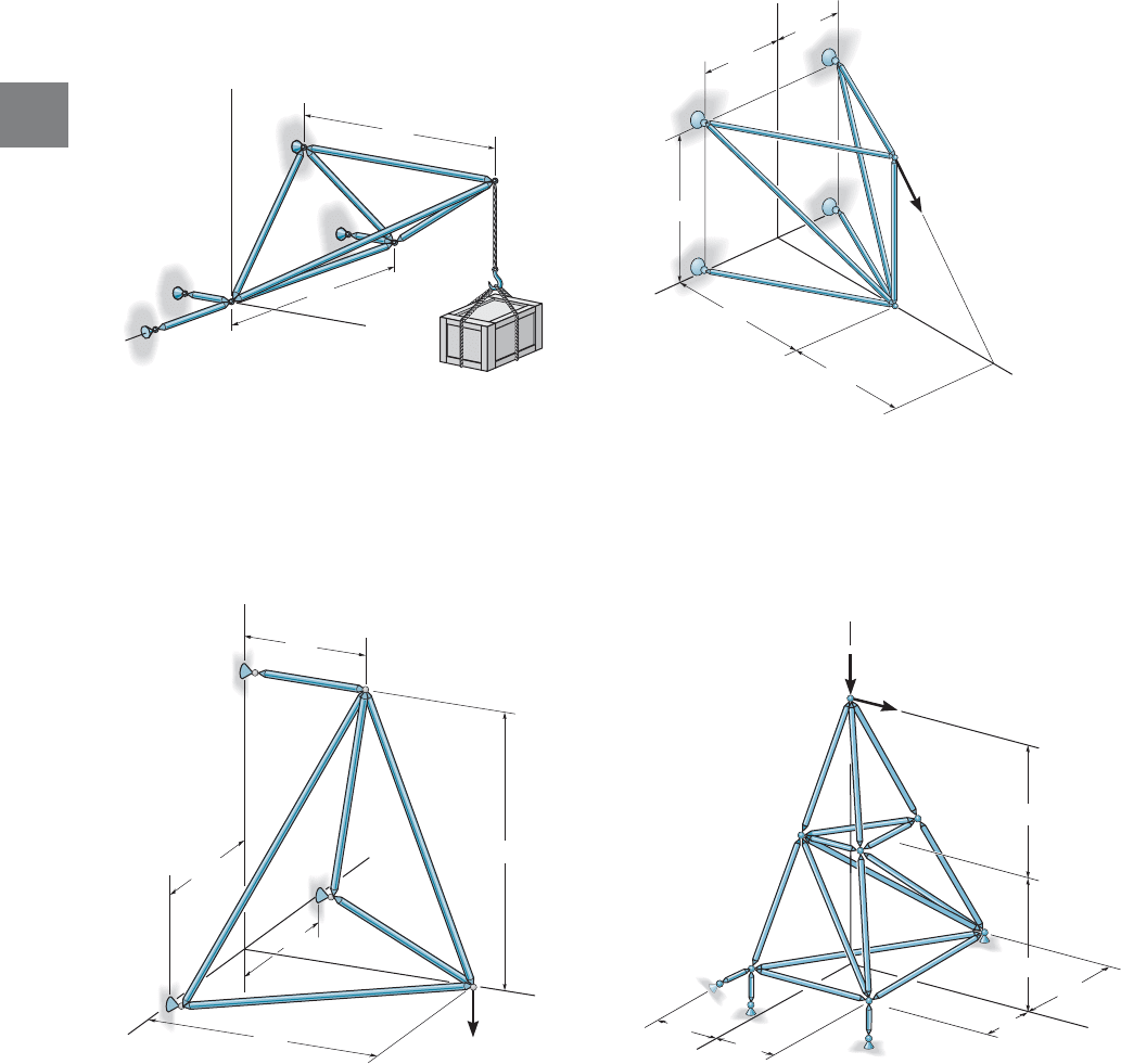
3.8 Space Trusses
A space truss consists of members joined together at their ends to form
a stable three-dimensional structure. In Sec. 3–2 it was shown that the
simplest form of a stable two-dimensional truss consists of the members
arranged in the form of a triangle. We then built up the simple plane
truss from this basic triangular element by adding two members at a
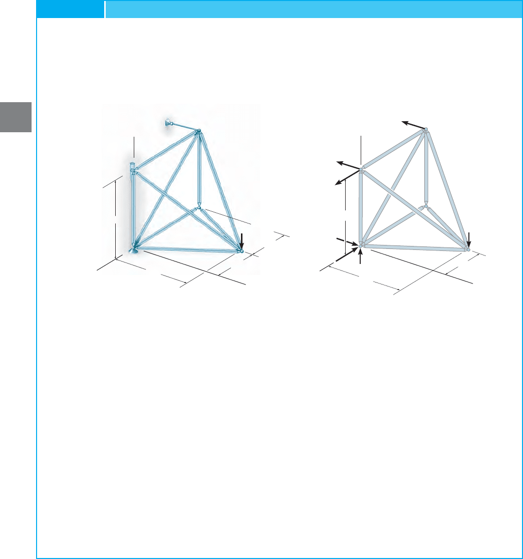
time to form further elements. In a similar manner, the simplest element
of a stable space truss is a tetrahedron, formed by connecting six members
together with four joints as shown in Fig. 3–34. Any additional members
added to this basic element would be redundant in supporting the force
P. A simple space truss can be built from this basic tetrahedral element
by adding three additional members and another joint forming
multiconnected tetrahedrons.
Determinacy and Stability. Realizing that in three dimensions
there are three equations of equilibrium available for each joint
then for a space truss with j number of joints, 3j
equations are available. If the truss has b number of bars and r number of
reactions, then like the case of a planar truss (Eqs. 3–1 and 3–2) we can write
(3–3)
The external stability of the space truss requires that the support
reactions keep the truss in force and moment equilibrium about any and
all axes.This can sometimes be checked by inspection, although if the truss
is unstable a solution of the equilibrium equations will give inconsistent
results. Internal stability can sometimes be checked by careful inspection
of the member arrangement. Provided each joint is held fixed by its
supports or connecting members, so that it cannot move with respect to
the other joints, the truss can be classified as internally stable. Also, if we
do a force analysis of the truss and obtain inconsistent results, then the
truss configuration will be unstable or have a “critical form.”
Assumptions for Design. The members of a space truss may be
treated as axial-force members provided the external loading is applied
at the joints and the joints consist of ball-and-socket connections. This
assumption is justified provided the joined members at a connection
intersect at a common point and the weight of the members can be
neglected. In cases where the weight of a member is to be included in the
analysis, it is generally satisfactory to apply it as a vertical force, half of its
magnitude applied to each end of the member.
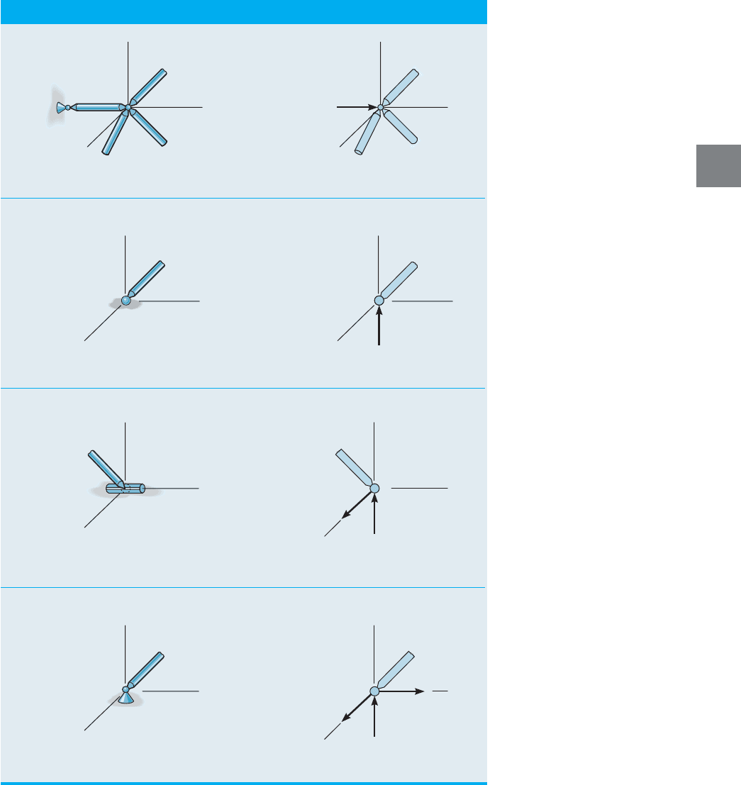
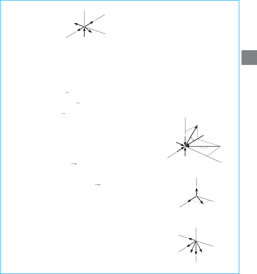
For the force analysis the supports of a space truss are generally
modeled as a short link, plane roller joint, slotted roller joint, or a
ball-and-socket joint. Each of these supports and their reactive force
components are shown in Table 3–1.
b + r 7 3j
statically indeterminate—check stability
b + r = 3j
statically determinate—check stability
b + r 6 3j
unstable truss
©F
y
= 0, ©F
z
= 02,
1©F
x
= 0,
Fig. 3–34
P
The roof of this pavilion is supported using
a system of space trusses.
3.8 SPACE TRUSSES 121
3
TABLE 3–1 Supports and Their Reactive Force Components
z
y
x
z
y
x
F
y
short link
z
y
x
(2)
(1)
roller
z
y
x
F
z
(3)
z
y
x
z
y
x
F
z
F
x
slotted roller constrained
in a cylinder
(4)
z
y
x
ball-and-socket
z
y
x
F
z
F
x
F
y
A
F
A
z
x
y
D
C
B
F
D
F
C
F
B
Fig. 3–36
122 CHAPTER 3ANALYSIS OF STATICALLY DETERMINATE TRUSSES
3
x
,
y
,
z
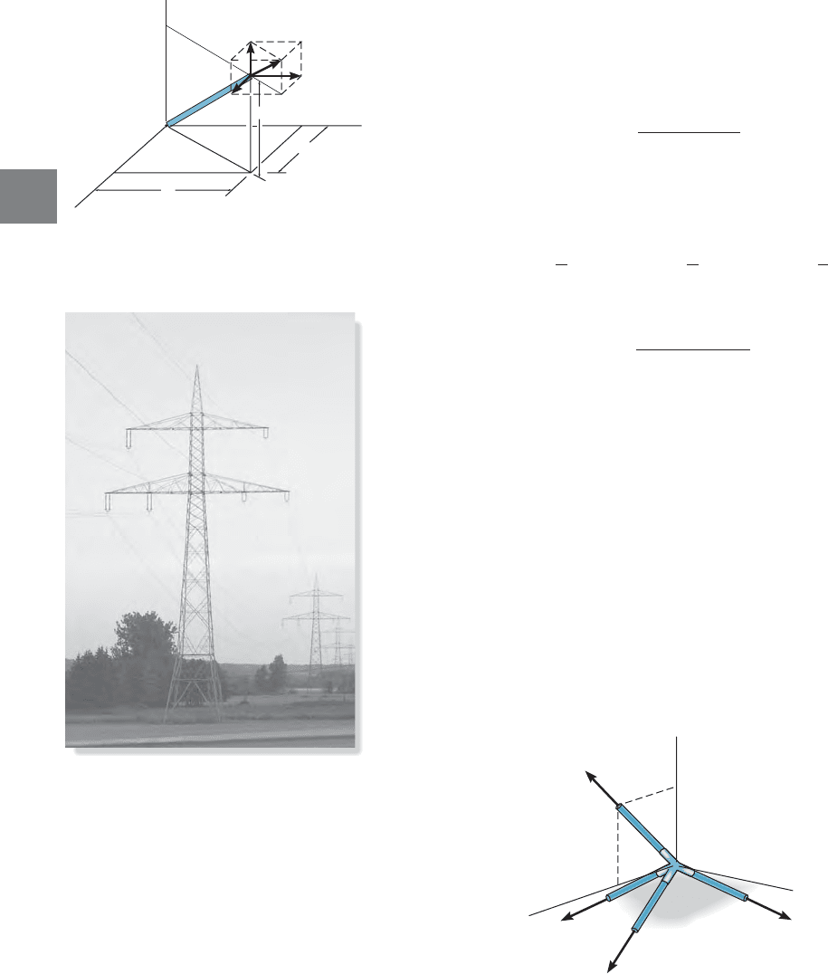
, Force Components. Since the analysis of a space truss is
three-dimensional, it will often be necessary to resolve the force F in a
member into components acting along the x, y, z axes. For example, in
Fig. 3–35 member AB has a length l and known projections x, y, z along
the coordinate axes. These projections can be related to the member’s
length by the equation
(3–4)
Since the force F acts along the axis of the member, then the
components of F can be determined by proportion as follows:
(3–5)
Notice that this requires
(3–6)
Use of these equations will be illustrated in Example 3–12.
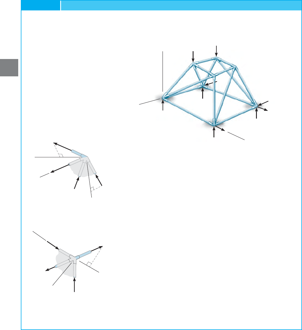
Zero-Force Members. In some cases the joint analysis of a truss
can be simplified if one is able to spot the zero-force members by
recognizing two common cases of joint geometry.
Case 1. If all but one of the members connected to a joint lie in the same
plane, and provided no external load acts on the joint, then the member
not lying in the plane of the other members must be subjected to zero
force. The proof of this statement is shown in Fig. 3–36, where members
A, B, C lie in the x–y plane. Since the z component of must be zero to
satisfy member D must be a zero-force member. By the same
reasoning, member D will carry a load that can be determined from
if an external force acts on the joint and has a component acting
along the z axis.
©F
z
= 0
©F
z
= 0,
F
D
F = 2F
2
x
+ F
2
y
+ F
2
z
F
x
= Fa
x
l
b
F
y
= Fa
y
l
b
F
z
= Fa
z
l
b
l = 2x
2
+ y
2
+ z
2
Fig. 3–35
z
F
y
F
F
z
F
x
B
x
x
A
l
z
y
y
Because of their cost effectiveness, towers
such as these are often used to support
multiple electric transmission lines.
3.8 SPACE TRUSSES 123
3
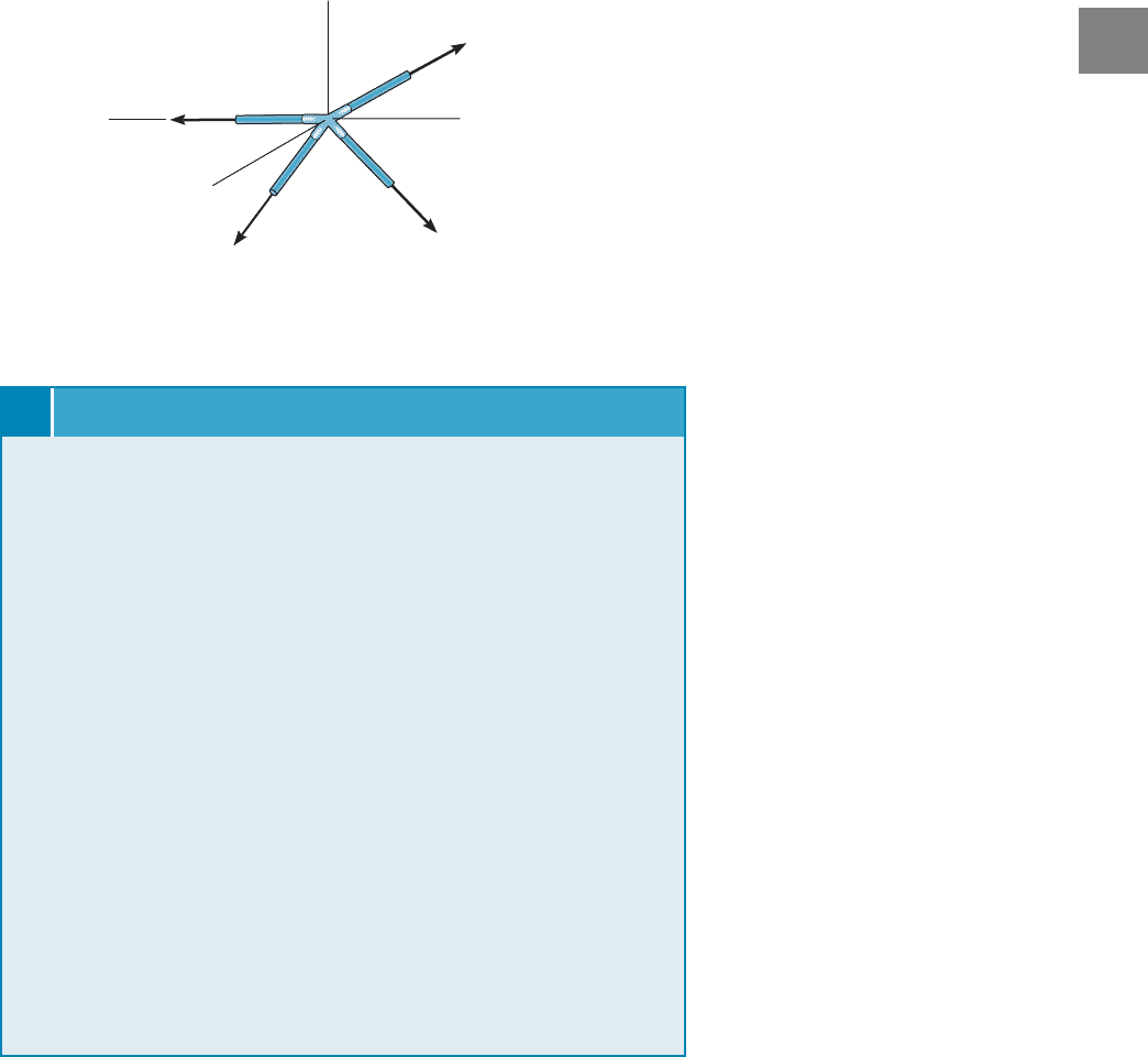
Case 2. If it has been determined that all but two of several members
connected at a joint support zero force, then the two remaining members
must also support zero force, provided they do not lie along the same line.
This situation is illustrated in Fig. 3–37, where it is known that A and C are
zero-force members. Since is collinear with the y axis, then application
of or requires the x or z component of to be zero.
Consequently, This being the case, since ©F
y
= 0.F
D
= 0F
B
= 0.
F
B
©F
z
= 0©F
x
= 0
F
D
B
z
x
y
D
A
F
A
0
F
B
F
D
C
F
C
0
Procedure for Analysis
Either the method of sections or the method of joints can be used to
determine the forces developed in the members of a space truss.
Method of Sections
If only a few member forces are to be determined, the method of
sections may be used. When an imaginary section is passed through a
truss and the truss is separated into two parts, the force system acting on
either one of the parts must satisfy the six scalar equilibrium equations:
By
proper choice of the section and axes for summing forces and moments,
many of the unknown member forces in a space truss can be computed
directly, using a single equilibrium equation. In this regard, recall that
the moment of a force about an axis is zero provided the force is parallel
to the axis or its line of action passes through a point on the axis.
Method of Joints
Generally, if the forces in all the members of the truss must be
determined, the method of joints is most suitable for the analysis.
When using the method of joints, it is necessary to solve the three
scalar equilibrium equations at each
joint. Since it is relatively easy to draw the free-body diagrams and
apply the equations of equilibrium, the method of joints is very
consistent in its application.
©F
z
= 0©F
y
= 0,©F
x
= 0,
©M
z
= 0.©M
y
= 0,©M
x
= 0,©F
z
= 0,©F
y
= 0,©F
x
= 0,
Particular attention should be directed to the foregoing two cases of
joint geometry and loading, since the analysis of a space truss can be
considerably simplified by first spotting the zero-force members.
Fig. 3–37
124 CHAPTER 3ANALYSIS OF STATICALLY DETERMINATE TRUSSES
3
Determine the force in each member of the space truss shown in
Fig. 3–38a. The truss is supported by a ball-and-socket joint at A,a
slotted roller joint at B, and a cable at C.
EXAMPLE 3.12
z
8 ft
8 ft
B
x
A
E
y
4 ft
4 ft
D
C
E
z
= 600 lb
(a)
z
8 ft
8 ft
x
y
4 ft
600 lb
(b)
A
y
A
x
B
y
B
x
C
y
A
z
SOLUTION
The truss is statically determinate since or
Fig. 3–38b.
Support Reactions. We can obtain the support reactions from the
free-body diagram of the entire truss, Fig. 3–38b, as follows:
A
z
= 600 lb A
z
- 600 = 0©F
z
= 0;
A
y
= 600 lb A
y
- 600 = 0©F
y
= 0;
A
x
= 300 lb 300 - A
x
= 0©F
x
= 0;
B
y
= 600 lb B
y
182- 600182= 0©M
x
= 0;
C
y
= 0©M
z
= 0;
B
x
= 300 lb-600142+ B
x
182= 0©M
y
= 0;
9 + 6 = 3152,b + r = 3j
Fig. 3–38
3.8 SPACE TRUSSES 125
3
Joint
B
. We can begin the method of joints at B since there are three
unknown member forces at this joint, Fig. 3–38c. The components of
can be determined by proportion to the length of member BE,as
indicated by Eqs. 3–5.We have
Ans.
Ans.
Ans.
Joint
A
. Using the result for the free-body
diagram of joint A is shown in Fig. 3–38d. We have
Ans.
Ans.
Ans.
Joint
D
. By inspection the members at joint D, Fig. 3–38a, support
zero force, since the arrangement of the members is similar to either
of the two cases discussed in reference to Figs. 3–36 and 3–37. Also,
from Fig. 3–38e,
Ans.
Ans.
Joint
C
. By observation of the free-body diagram, Fig. 3–38f,
Ans.F
CE
= 0
F
DC
= 0©F
z
= 0;
F
DE
= 0©F
x
= 0;
F
AD
= 0
-300 + F
AD
+ 670.8
A
1
15
B
= 0©F
x
= 0;
F
AE
= 670.8 lb 1C2
-F
AE
A
2
15
B
+ 600 = 0©F
y
= 0;
F
AC
= 0
600 - 600 + F
AC
sin 45° = 0©F
z
= 0;
F
BA
= 600 lb 1C2,
F
BA
- 900
A
8
12
B
= 0
F
BA
= 600 lb 1C2©F
z
= 0;
300 - F
BC
- 900
A
4
12
B
= 0
F
BC
= 0©F
x
= 0;
-600 + F
BE
A
8
12
B
= 0
F
BE
= 900 lb 1T2©F
y
= 0;
F
BE
z
y
x
F
CE
0
C
(
f
)
0
0
0
B
300 lb
600 lb
F
BA
F
BE
F
BC
x
y
z
(c)
y
600 lb
z
300 lb
600 lb
600 lb
F
AE
F
AD
F
AC
x
1
2
45
(d)
A
z
y
x
F
DC
F
DE
0
D
(e)
126 CHAPTER 3ANALYSIS OF STATICALLY DETERMINATE TRUSSES
3
Fig. 3–39
Determine the zero-force members of the truss shown in Fig. 3–39a.
The supports exert components of reaction on the truss as shown.
EXAMPLE 3.13
SOLUTION
The free-body diagram, Fig. 3–39a, indicates there are eight unknown
reactions for which only six equations of equilibrium are available for
solution. Although this is the case, the reactions can be determined,
since or
To spot the zero-force members, we must compare the conditions of
joint geometry and loading to those of Figs. 3–36 and 3–37. Consider
joint F, Fig. 3–39b. Since members FC, FD, FE lie in the x–y plane
and FG is not in this plane, FG is a zero-force member. (
must be satisfied.) In the same manner, from joint E, Fig. 3–39c, EF is
a zero-force member, since it does not lie in the y–z plane. (
must be satisfied.) Returning to joint F, Fig. 3–39b, it can be seen that
since and there are no external
forces acting on the joint. Use this procedure to show that AB is a
zero force member.
The numerical force analysis of the joints can now proceed by
analyzing joint to determine the forces in GH, GB, GC.
Then analyze joint H to determine the forces in HE, HB, HA; joint E
to determine the forces in EA, ED; joint A to determine the forces in
AB, AD, and joint B to determine the force in BC and
joint D to determine the force in DC and and finally, joint C to
determine C
z
.C
y
,C
x
,
D
z
;D
y
,
B
z
;B
x
,A
z
;
G 1F
GF
= 02
F
FE
= F
FG
= 0,F
FD
= F
FC
= 0,
©F
x–
= 0
©F
z¿
= 0
16 + 8 = 3182.b + r = 3j
x
z
A
H
G
F
E
B
D
C
B
z
A
z
D
y
C
z
C
y
C
x
D
z
B
x
y
2 kN
4 kN
(a)
(b)
F
F
FE
F
FG
F
FD
F
FC
x¿
z¿
y¿
E
x¿¿
y¿¿
z¿¿
(c)
F
E
F
F
EA
F
EH
F
ED
3.8 SPACE TRUSSES 127
3
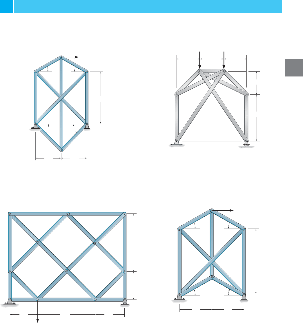
3–29. Determine the forces in all the members of the
lattice (complex) truss. State if the members are in tension
or compression. Hint: Substitute member JE by one placed
between K and F.
3–31. Determine the force in all the members of the
complex truss. State if the members are in tension or
compression.
*3–28. Determine the forces in all the members of the
complex truss. State if the members are in tension or
compression. Hint: Substitute member AD with one placed
between E and C.
3–30. Determine the force in each member and state if the
members are in tension or compression.
PROBLEMS
Prob. 3–29
Prob. 3–30
Prob. 3–28
Prob. 3–31
D
E
B
C
A
F
600 lb
6 ft 6 ft
12 ft
3030
45 45
B
A
E
F
C
D
1 m 1 m 1 m
1 m
2 m
4 kN 4 kN
KJ
C
E
D
F
G
HI
L
B
A
6 ft
12 ft
6 ft
6 ft 12 ft
2 k
D
E
B
C
A
F
4 kN
3 m 3 m
6 m
3030
30
30
128 CHAPTER 3ANALYSIS OF STATICALLY DETERMINATE TRUSSES
3
Prob. 3–32
*3–32. Determine the force developed in each member of
the space truss and state if the members are in tension or
compression. The crate has a weight of 150 lb.
3–34. Determine the force in each member of the space
truss and state if the members are in tension or compression.
The truss is supported by ball-and socket joints at C, D, E,
and G. Note: Although this truss is indeterminate to the first
degree, a solution is possible due to symmetry of geometry
and loading.
3–33. Determine the force in each member of the space
truss and state if the members are in tension or compression.
Hint: The support reaction at E acts along member EB.
Why?
3–35. Determine the force in members FE and ED of the
space truss and state if the members are in tension or
compression. The truss is supported by a ball-and-socket
joint at C and short links at A and B.
*3–36. Determine the force in members GD, GE, and FD
of the space truss and state if the members are in tension or
compression.
Prob. 3–33
Probs. 3–35/3–36
Prob. 3–34
x
y
z
A
B
C
6 ft
6 ft
6 ft
6 ft
D
G
A
F 3 kN
B
C
E
y
z
x
D
1 m
2 m
2 m
1.5 m
1 m
y
x
D
A
6 kN
C
B
E
z
5 m
2 m
4 m
3 m
3 m
z
x
y
500 lb
200 lb
6 ft
6 ft
F
E
D
G
C
4 ft
2 ft
3 ft
3 ft
A
B
PROJECT PROBLEM 129
3
Prob. 3–37
3–37. Determine the force in each member of the space
truss. Indicate if the members are in tension or compression.
3–38. Determine the force in members BE, DF, and BC of
the space truss and state if the members are in tension or
compression.
3–39. Determine the force in members CD, ED, and CF
of the space truss and state if the members are in tension or
compression.
Probs. 3–38/3–39
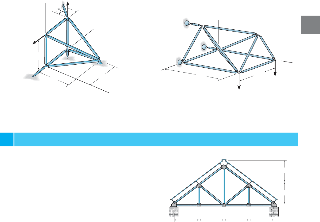
3–1P. The Pratt roof trusses are uniformly spaced every
15 ft. The deck, roofing material, and the purlins have an
average weight of . The building is located in
New York where the anticipated snow load is and
the anticipated ice load is .These loadings occur over
the horizontal projected area of the roof. Determine the
force in each member due to dead load, snow, and ice loads.
Neglect the weight of the truss members and assume A is
pinned and E is a roller.
8 lb>ft
2
20 lb>ft
2
5.6 lb>ft
2
PROJECT PROBLEM
Project Prob. 3–1P
2 m
2 m
2 m
E
A
3 m
F
D
C
B
2 kN
2 m
z
y
x
2 kN
8 ft 8 ft 8 ft 8 ft
6 ft
6 ft
A
B
H
G
F
CD
E
2 m
z
y
x
2 kN
E
A
B
D
C
2 m
2 m
45
4 kN