Hibbeler R.C. Structural Analysis
Подождите немного. Документ загружается.


130 CHAPTER 3ANALYSIS OF STATICALLY DETERMINATE TRUSSES
3
Trusses are composed of slender members joined together at their end points to form a series of triangles.
If the number of bars or members of a truss is b, and
there are r reactions and j joints, then if
the truss will be statically determinate
the truss will be statically indeterminateb + r 7 2j
b + r = 2j
T T
C
C
For analysis we assume the members are pin connected,
and the loads are applied at the joints. Thus, the members
will either be in tension or compression.
Trusses can be classified in three ways:
Simple trusses are formed by starting with an initial triangular element and connecting to it two other members and a joint
to form a second triangle, etc.
Compound trusses are formed by connecting together two or more simple trusses using a common joint and/or additional
member.
Complex trusses are those that cannot be classified as either simple or compound.
CHAPTER REVIEW
simple truss
compound truss
simple
trusses
complex truss
compound truss
simple
trusses

CHAPTER REVIEW 131
3
unstable–concurrent reactions
unstable–parallel reactions
unstable internally
The truss will be externally unstable if the reactions are concurrent or parallel.
Internal stability can be checked by counting the number of bars b, reactions r, and joints j.
If the truss is unstable.
If it may still be unstable, so it becomes necessary to inspect the truss and look for bar arrangements that form
a parallel mechanism, without forming a triangular element.
b + r Ú 2j
b + r 6 2j
Planar trusses can be analyzed by the method of joints.
This is done by selecting each joint in sequence, having at
most one known force and at least two unknowns. The
free-body diagram of each joint is constructed and two
force equations of equilibrium, , are
written and solved for the unknown member forces.
The method of sections requires passing a section
through the truss and then drawing a free-body diagram
of one of its sectioned parts. The member forces cut by
the section are then found from the three equations of
equilibrium. Normally a single unknown can be found if
one sums moments about a point that eliminates the two
other forces.
Compound and complex trusses can also be analyzed
by the method of joints and the method of sections. The
“method of substitute members” can be used to obtain a
direct solution for the force in a particular member of a
complex truss.
©F
x
= 0, ©F
y
= 0

The simply supported beams and girders of this building frame were designed
to resist the internal shear and moment acting throughout their lengths.

4
133
Before a structural member can be proportioned, it is necessary to
determine the force and moment that act within it. In this chapter we
will develop the methods for finding these loadings at specified points
along a member’s axis and for showing the variation graphically using
the shear and moment diagrams. Applications are given for both
beams and frames.
4.1 Internal Loadings at a Specified Point
As discussed in Sec. 2–3, the internal load at a specified point in a member
can be determined by using the method of sections. In general, this
loading for a coplanar structure will consist of a normal force N, shear
force V, and bending moment M.* It should be realized, however, that
these loadings actually represent the resultants of the stress distribution
acting over the member’s cross-sectional area at the cut section. Once
the resultant internal loadings are known, the magnitude of the stress
can be determined provided an assumed distribution of stress over the
cross-sectional area is specified.
Internal Loadings
Developed in
Structural Members
*Three-dimensional frameworks can also be subjected to a torsional moment, which
tends to twist the member about its axis.

134 CHAPTER 4INTERNAL LOADINGS DEVELOPED IN S TRUCTURAL MEMBERS
4
Sign Convention. Before presenting a method for finding the internal
normal force, shear force, and bending moment, we will need to establish
a sign convention to define their “positive” and “negative” values.*
Although the choice is arbitrary, the sign convention to be adopted here
has been widely accepted in structural engineering practice, and is
illustrated in Fig. 4–1a. On the left-hand face of the cut member the
normal force N acts to the right, the internal shear force V acts
downward, and the moment M acts counterclockwise. In accordance
with Newton’s third law, an equal but opposite normal force, shear force,
and bending moment must act on the right-hand face of the member at
the section. Perhaps an easy way to remember this sign convention is to
isolate a small segment of the member and note that positive normal
force tends to elongate the segment, Fig. 4–1b; positive shear tends to rotate
the segment clockwise, Fig. 4–1c; and positive bending moment tends to
bend the segment concave upward, so as to “hold water,” Fig. 4–1d.
Fig. 4–1
*This will be convenient later in Secs. 4–2 and 4–3 where we will express V and M as
functions of x and then plot these functions. Having a sign convention is similar to assigning
coordinate directions x positive to the right and y positive upward when plotting a function
y = f1x2.
M
N
V
N
V
M
(a)
NN
(b)
V
V
(c)
MM
(
d
)

4.1 INTERNAL LOADINGS AT A SPECIFIED POINT 135
4
Procedure for Analysis
The following procedure provides a means for applying the method
of sections to determine the internal normal force, shear force, and
bending moment at a specific location in a structural member.
Support Reactions
• Before the member is “cut” or sectioned, it may be necessary to
determine the member’s support reactions so that the equilibrium
equations are used only to solve for the internal loadings when
the member is sectioned.
• If the member is part of a pin-connected structure, the pin
reactions can be determined using the methods of Sec. 2–5.
Free-Body Diagram
• Keep all distributed loadings, couple moments, and forces acting
on the member in their exact location, then pass an imaginary
section through the member, perpendicular to its axis at the point
where the internal loading is to be determined.
• After the section is made, draw a free-body diagram of the
segment that has the least number of loads on it. At the section
indicate the unknown resultants N, V, and M acting in their
positive directions (Fig. 4–1a).
Equations of Equilibrium
• Moments should be summed at the section about axes that pass
through the centroid of the member’s cross-sectional area, in
order to eliminate the unknowns N and V and thereby obtain a
direct solution for M.
• If the solution of the equilibrium equations yields a quantity
having a negative magnitude, the assumed directional sense of
the quantity is opposite to that shown on the free-body diagram.

136 CHAPTER 4INTERNAL LOADINGS DEVELOPED IN S TRUCTURAL MEMBERS
4
EXAMPLE 4.1
1 m
(a)
1 m 1 m 1 m 1 m 1 m 1 m 1 m 1 m 1 m 1 m 1 m
1.2 m 1.2 m 1.2 m
3.6 kN 3.6 kN7.2 kN
girder
43.2 kN43.2 kN
C
7.2 kN 7.2 kN
edge
beam
girder
Fig. 4–2
(b)
7.2 kN
beam
0.5 m
0.5 m
1.8 kN/m
7 m
7.2 kN
girder
(
c
)
M
C
V
C
43.2 kN
1 m
1 m
0.4 m
1.2 m 1.2 m
3.6 kN 7.2 kN 7.2 kN
C
The building roof shown in the photo has a weight of and is
supported on 8-m long simply supported beams that are spaced 1 m
apart. Each beam, shown in Fig. 4–2b transmits its loading to two
girders, located at the front and back of the building. Determine the
internal shear and moment in the front girder at point C,Fig.4–2a.
Neglect the weight of the members.
1.8 kN>m
2
Free-Body Diagram. The free-body diagram of the girder is shown
in Fig. 4–2a. Notice that each column reaction is
The free-body diagram of the left girder segment is shown in Fig. 4–2c.
Here the internal loadings are assumed to act in their positive directions.
Equations of Equilibrium
[1213.6 kN2+ 1117.2 kN2]>2 = 43.2 kN
Ans.
Ans.M
C
= 30.2 kN
#
m- 43.211.22= 0M
C
+ 7.210.42+ 7.211.42+ 3.612.42d+©M
C
= 0;
V
C
= 25.2 kN43.2 - 3.6 - 217.22- V
C
= 0+
c
©F
y
= 0;
SOLUTION
Support Reactions. The roof loading is transmitted to each beam
as a one-way slab . The tributary loading
on each interior beam is therefore
(The two edge beams support .) From Fig. 4–2b, the reaction
of each interior beam on the girder is 11.8 kN>m218 m2>2 = 7.2 kN.
0.9 kN>m
1.8 kN>m.11.8 kN>m
2
211 m2=
1L
2
>L
1
= 8 m>1 m = 8 7 22

4.1 INTERNAL LOADINGS AT A SPECIFIED POINT 137
4
EXAMPLE 4.2
Determine the internal shear and moment acting at a section passing
through point C in the beam shown in Fig. 4–3a.
SOLUTION
Support Reactions. Replacing the distributed load by its resultant
force and computing the reactions yields the results shown in Fig. 4–3b.
Free-Body Diagram. Segment AC will be considered since it yields
the simplest solution, Fig. 4–3c. The distributed load intensity at C is
computed by proportion, that is,
Equations of Equilibrium.
Ans.
Ans.
This problem illustrates the importance of keeping the distributed
loading on the beam until after the beam is sectioned. If the beam in
Fig. 4–3b were sectioned at C, the effect of the distributed load on
segment AC would not be recognized, and the result and
would be wrong.M
C
= 54 k
#
ft
V
C
= 9 k
-9162+ 3122+ M
C
= 0
M
C
= 48 k
#
ftd+©M
C
= 0;
V
C
= 6 k9 - 3 - V
C
= 0+
c
©F
y
= 0;
w
C
= 16 ft>18 ft213 k>ft2= 1 k>ft
A
6 ft
18 ft
C
(a)
3 k/ft
B
27 k
12 ft
(
b
)
6 ft
9 k 18 k
Fig. 4–3
1 k/ft
N
C
M
C
9 k
6 ft
2 ft
3 k
(
c
)
V
C

138 CHAPTER 4INTERNAL LOADINGS DEVELOPED IN S TRUCTURAL MEMBERS
4
EXAMPLE 4.3
The 9-k force in Fig. 4–4a is supported by the floor panel DE, which in
turn is simply supported at its ends by floor beams. These beams
transmit their loads to the simply supported girder AB. Determine the
internal shear and moment acting at point C in the girder.
12 ft 6 ft
4 ft
2 ft
9 k
3 k
5.25 k
24 ft
3.75 k
(b)
3 k
6 k
6 k
C
M
C
V
C
N
C
A
12 ft 3 ft
3.75 k
6 k
(c)
Ans.
Ans. -3.751152+ 6132+ M
C
= 0
M
C
= 38.25 k
#
ftd+©M
C
= 0;
V
C
=-2.25 k 3.75 - 6 - V
C
= 0+c©F
y
= 0;
SOLUTION
Support Reactions. Equilibrium of the floor panel, floor beams, and
girder is shown in Fig. 4–4b. It is advisable to check these results.
Free-Body Diagram. The free-body diagram of segment AC of the
girder will be used since it leads to the simplest solution, Fig. 4–4c.
Note that there are no loads on the floor beams supported by AC.
Equations of Equilibrium.
(a)
6 ft
6 ft
6 ft
4 ft
2 ft
9 k
A
B
C
D
E
15 ft
24 ft
Fig. 4–4
4.2 SHEAR AND MOMENT FUNCTIONS 139
4
4.2 Shear and Moment Functions
The design of a beam requires a detailed knowledge of the variations of
the internal shear force V and moment M acting at each point along the
axis of the beam. The internal normal force is generally not considered
for two reasons: (1) in most cases the loads applied to a beam act
perpendicular to the beam’s axis and hence produce only an internal
shear force and bending moment, and (2) for design purposes the beam’s
resistance to shear, and particularly to bending, is more important than
its ability to resist normal force. An important exception to this occurs,
however, when beams are subjected to compressive axial forces, since
the buckling or instability that may occur has to be investigated.
The variations of V and M as a function of the position x of an arbitrary
point along the beam’s axis can be obtained by using the method of
sections discussed in Sec. 4–1. Here, however, it is necessay to locate the
imaginary section or cut at an arbitrary distance x from one end of the
beam rather than at a specific point.
In general, the internal shear and moment functions will be discontinuous,
or their slope will be discontinuous, at points where the type or magnitude
of the distributed load changes or where concentrated forces or couple
moments are applied. Because of this, shear and moment functions
must be determined for each region of the beam located between any
two discontinuities of loading. For example, coordinates and
will have to be used to describe the variation of V and M throughout
the length of the beam in Fig. 4–5a. These coordinates will be valid only
within regions from A to B for from B to C for and from C to D
for Although each of these coordinates has the same origin, as noted
here, this does not have to be the case. Indeed, it may be easier to
develop the shear and moment functions using coordinates
having origins at A, B, and D as shown in Fig. 4–5b. Here and are
positive to the right and is positive to the left.x
3
x
2
x
1
x
3
x
2
,x
1
,
x
3
.
x
2
,x
1
,
x
3
x
2
,x
1
,
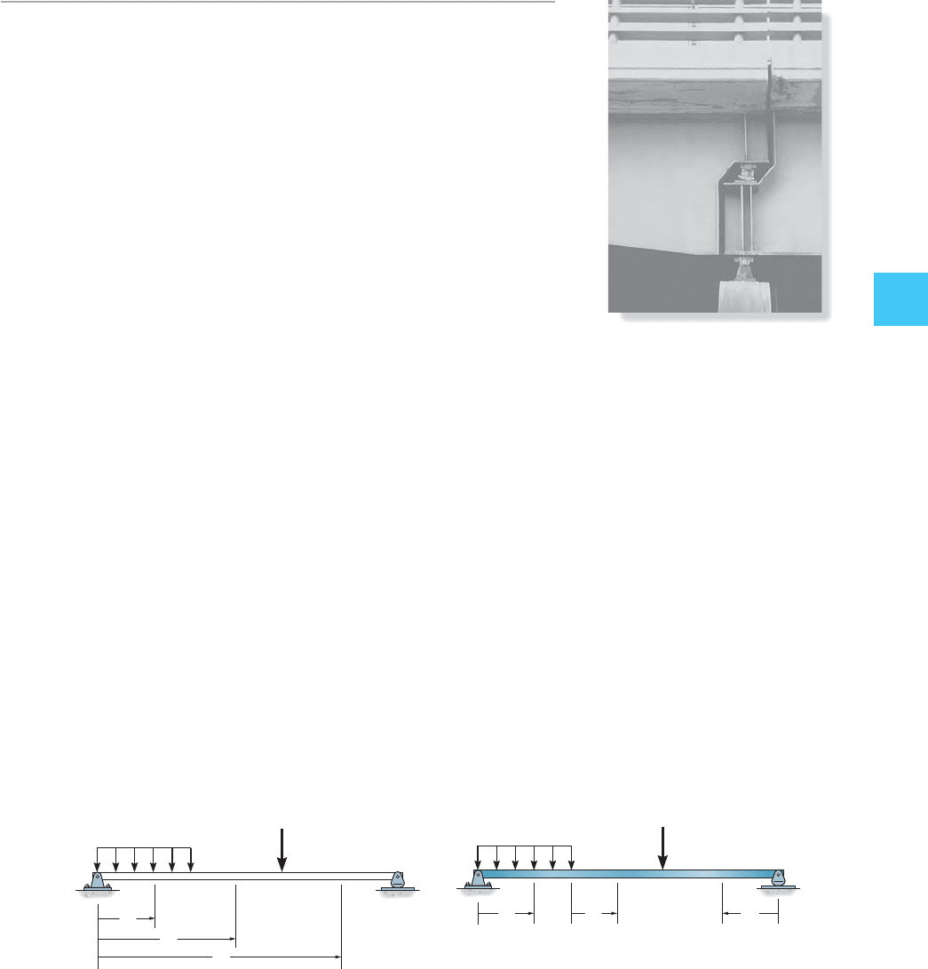
Additional reinforcement, provided by ver-
tical plates called stiffeners, is used over the
pin and rocker supports of these bridge
girders. Here the reactions will cause large
internal shear in the girders and the stiff-
eners will prevent localized buckling of the
girder flanges or web. Also, note the tipping
of the rocker support caused by the thermal
expansion of the bridge deck.
A
B
C
D
P
w
x
1
x
2
x
3
(
a
)
A
BC
D
P
w
x
1
x
2
x
3
(b)
Fig. 4–5