Hibbeler R.C. Structural Analysis
Подождите немного. Документ загружается.


160 CHAPTER 4INTERNAL LOADINGS DEVELOPED IN S TRUCTURAL MEMBERS
4
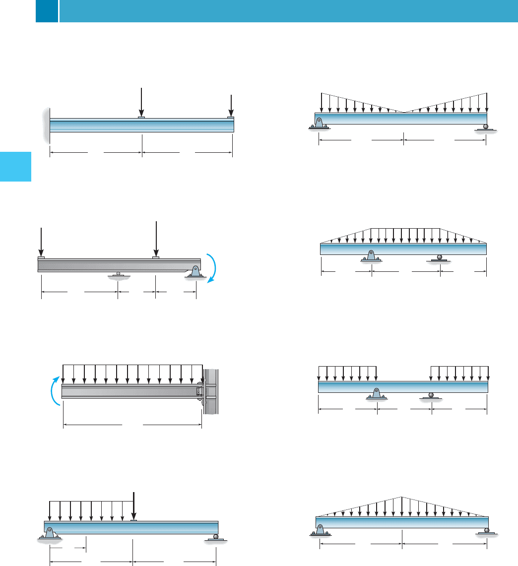
FUNDAMENTAL PROBLEMS
F4–13. Draw the shear and moment diagrams for the
beam. Indicate values at the supports and at the points
where a change in load occurs.
F4–17. Draw the shear and moment diagrams for the
beam. Indicate values at the supports and at the points
where a change in load occurs.
F4–19. Draw the shear and moment diagrams for the
beam. Indicate values at the supports and at the points
where a change in load occurs.
B
2 m
2 m
3 kN
A
8 kN
F4–13
B
A
4 m 2 m
2 m
6 kN
6 kN · m
8 kN
F4–14
2 k/ft
A
10 ft
30 k·ft
F4–15
F4–14. Draw the shear and moment diagrams for the
beam. Indicate values at the supports and at the points
where a change in load occurs.
F4–15. Draw the shear and moment diagrams for the
beam. Indicate values at the supports and at the points
where a change in load occurs.
F4–16. Draw the shear and moment diagrams for the
beam. Indicate values at the supports and at the points
where a change in load occurs.
12 ft 12 ft
6 k/ft
A
B
18 k
x
F4–16
A
B
2 kN/m
2 kN/m
4.5 m
4.5 m
F4–17
A
B
4 kN
/
m
1.5 m
2 m
1.5 m
F4–18
A
B
6 kN/m
2 m 2 m 2 m
6 kN/m
F4–19
F4–18. Draw the shear and moment diagrams for the
beam. Indicate values at the supports and at the points
where a change in load occurs.
F4–20. Draw the shear and moment diagrams for the
beam. Indicate values at the supports and at the points
where a change in load occurs.
A
B
2 k/ft
6 ft 6 ft
F4–20

4–23. Draw the shear and moment diagrams for the beam.
4–26. Draw the shear and moment diagrams for the beam.
PROBLEMS
6 ft
A
CD
E
B
6 ft
2 ft
4 ft 4 ft
500 lb
200 lb
300 lb
Prob. 4–23
4 ft4 ft4 ft4 ft4 ft
2 k 2 k 2 k
4 ft4 ft4 ft4 ft4 ft
A
2 k
Prob. 4–24
*4–24. Draw the shear and moment diagrams for the beam.
4–25. Draw the shear and moment diagrams for the beam.
BD
A
2 m
1 m
2 m
1 m
0.4 m
6 kN
3
5
4
C
0.6 m
20 kN · m
Prob. 4–25
10 k 8 k
ACB
0.8 k/ft
6 ft 6 ft12 ft 12 ft
Prob. 4–26
x
15 ft
600 lb⭈ft
A
B
400 lb/ft
Prob. 4–27
L/3 L/3 L/3
M
0
M
0
Prob. 4–28
C
A
B
2 m
3 m
1.5 kN/m
Prob. 4–29
4–27. Draw the shear and moment diagrams for the beam.
*4–28. Draw the shear and moment diagrams for the
beam (a) in terms of the parameters shown; (b) set
L = 8 m.M
0
= 500 N
#
m,
4.3 S
HEAR AND MOMENT DIAGRAMS FOR A BEAM 161
4–29. Draw the shear and moment diagrams for the beam.

162 CHAPTER 4INTERNAL LOADINGS DEVELOPED IN S TRUCTURAL MEMBERS
4
4–30. Draw the shear and bending-moment diagrams for
the beam.
4–34. Draw the shear and moment diagrams for the beam.
C
A
B
20 ft 10 ft
50 lb/ft
200 lb⭈ft
Prob. 4–30
C
w
A
B
L
L
––
2
Prob. 4–31
250 lb/ft
150 lb
⭈ ft150 lb ⭈ ft
AB
20 ft
Prob. 4–32
40 kN/m
20 kN
150 k
N⭈m
A
B
8 m 3 m
Prob. 4–33
4–31. Draw the shear and moment diagrams for the beam.
*
4–36. Draw the shear and moment diagrams of the beam.
Assume the support at B is a pin and A is a roller.
4–33. Draw the shear and moment diagrams for the beam.
*4–32. Draw the shear and moment diagrams for the beam.
x
4 ft 4 ft 4 ft 4 ft
200 lb/ft
CD E F G
A B
Prob. 4–34
AB
200 lb/ft
30 ft
800 lb
1200 lb⭈ ft
Prob. 4–35
A
B
800 lb · ft
100 lb/ft
16 ft
4 ft
Prob. 4–36
B
8 kN/m
1.5 m 6 m
A
Prob. 4–37
4–35. Draw the shear and moment diagrams for the beam.
4–37. Draw the shear and moment diagrams for the beam.
Assume the support at B is a pin.

4.4 SHEAR AND MOMENT DIAGRAMS FOR A FRAME 163
4
4.4 Shear and Moment Diagrams
for a Frame
Recall that a frame is composed of several connected members that are
either fixed or pin connected at their ends. The design of these
structures often requires drawing the shear and moment diagrams for
each of the members. To analyze any problem, we can use the
procedure for analysis outlined in Sec. 4–3. This requires first
determining the reactions at the frame supports. Then, using the
method of sections, we find the axial force, shear force, and moment
acting at the ends of each member. Provided all loadings are resolved
into components acting parallel and perpendicular to the member’s
axis, the shear and moment diagrams for each member can then be
drawn as described previously.
When drawing the moment diagram, one of two sign conventions is
used in practice. In particular, if the frame is made of reinforced concrete,
designers often draw the moment diagram positive on the tension side of
the frame. In other words, if the moment produces tension on the outer
surface of the frame, the moment diagram is drawn positive on this side.
Since concrete has a low tensile strength, it will then be possible to tell at
a glance on which side of the frame the reinforcement steel must be
placed. In this text, however, we will use the opposite sign convention
and always draw the moment diagram positive on the compression side of
the member. This convention follows that used for beams discussed in
Sec. 4–1.
The following examples illustrate this procedure numerically.
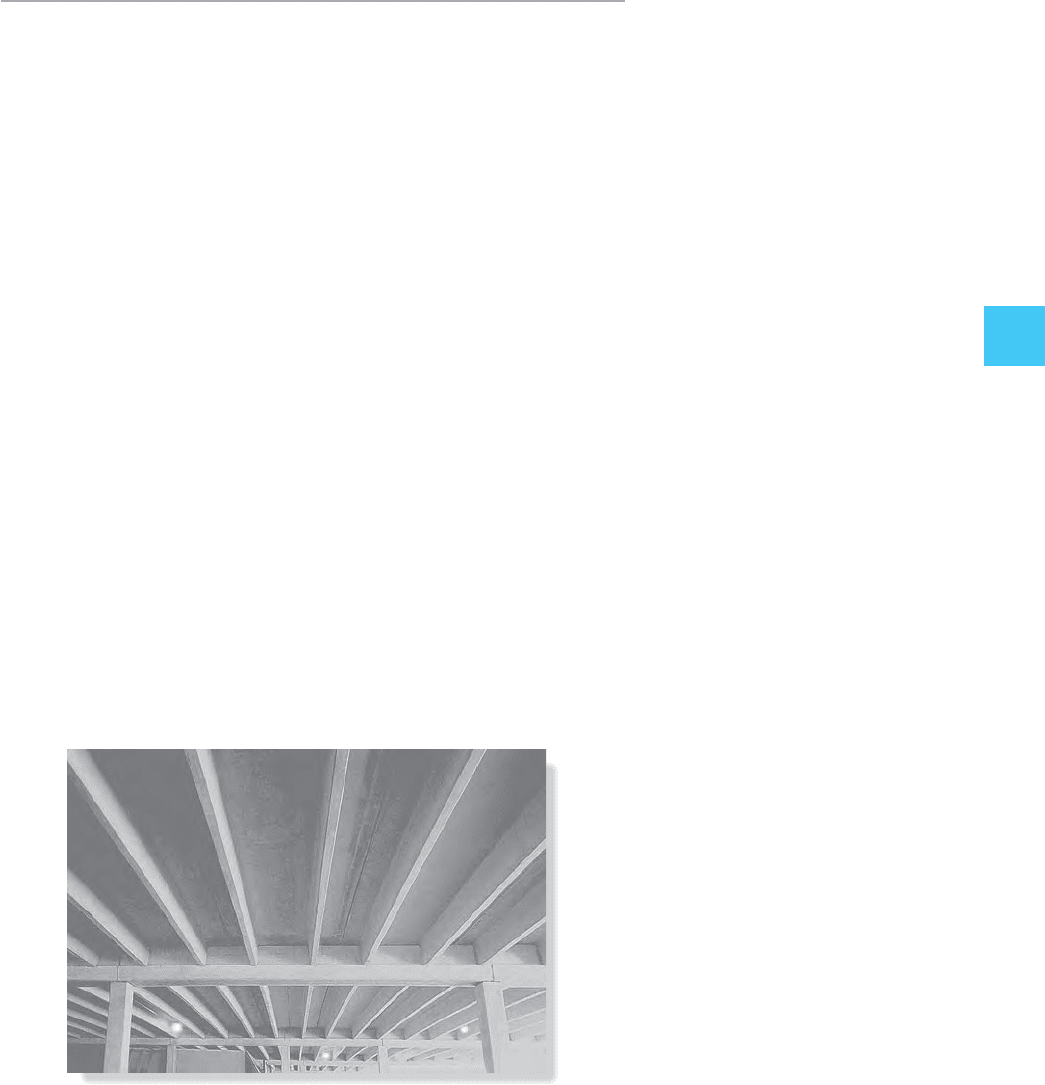
The simply supported girder of this concrete building frame was
designed by first drawing its shear and moment diagrams.

164 CHAPTER 4INTERNAL LOADINGS DEVELOPED IN S TRUCTURAL MEMBERS
4
Draw the moment diagram for the tapered frame shown in Fig. 4–17a.
Assume the support at A is a roller and B is a pin.
EXAMPLE 4.13
15 ft
5 k
C
5 ft
6 ft
3 k
(a)
A
B
Fig. 4–17
15 ft
5 k
5 ft
6 ft
3 k
3 k
1 k
(b)
6 k
5 ft
3 k
6 k
15 kft
3 k
6 k
A
5 k
1 k
3 k
15 kft
3 k
15 kft
C
6 k
15 kft
3 k
1 k
B
15 ft
1 k
3 k
(c)
15
15
15
6
11
(d)
M (kft)
member CB
member AC
M (kft)
x (ft)
x (ft)
SOLUTION
Support Reactions. The support reactions are shown on the
free-body diagram of the entire frame, Fig. 4–17b. Using these results,
the frame is then sectioned into two members, and the internal reac-
tions at the joint ends of the members are determined, Fig. 4–17c.
Note that the external 5-k load is shown only on the free-body diagram
of the joint at C.
Moment Diagram. In accordance with our positive sign convention,
and using the techniques discussed in Sec. 4–3, the moment diagrams
for the frame members are shown in Fig. 4–17d.

4.4 SHEAR AND MOMENT DIAGRAMS FOR A FRAME 165
4
EXAMPLE 4.14
Draw the shear and moment diagrams for the frame shown in
Fig. 4–18a. Assume A is a pin, C is a roller, and B is a fixed joint.
Neglect the thickness of the members.
SOLUTION
Notice that the distributed load acts over a length of
The reactions on the entire frame are calculated
and shown on its free-body diagram, Fig. 4–18b. From this diagram the
free-body diagrams of each member are drawn, Fig. 4–18c.The
distributed loading on BC has components along BC and perpendicular
to its axis of
as shown. Using these results, the shear and moment diagrams are
also shown in Fig. 4–18c.
10.1414 k>ft2 cos 45° = 10.1414 k>ft2 sin 45° = 0.1 k>ft
10 ft 22 = 14.14 ft.
10 ft
14.14 ft
1.06
5
0.354 k
10.6
0.625
0.5 k
0.5 k
2 k
2 k
(c)
0.5 k
1.06 k
1.77 k
1.77 k
2 k
0.5 k
1.06 k
0.1 k/ft
0.1 k/ft
5 kft
5 kft
5 kft
5 kft
M (kft)
M (kft)
V (k)
x (ft)
0.5
V (k)
x (ft)
–5
x (ft)
x (ft)
Fig. 4–18
10 ft
0.1414 k/ft
10 ft
10 ft
A
B
C
(a)
20 ft
5 ft
(0.1414 k/ft)(14.14 ft) 2 k
0.5 k
0.5 k
2 k
(b)

166 CHAPTER 4INTERNAL LOADINGS DEVELOPED IN S TRUCTURAL MEMBERS
4
EXAMPLE 4.15
Draw the shear and moment diagrams for the frame shown in Fig. 4–19a.
Assume A is a pin, C is a roller, and B is a fixed joint.
40 kN/m
B
4 m
4 m
C
3 m
2 m
80 kN
A
(a)
Fig. 4–19
120 kN
2 m6 m
80 kN
(b)
1.5 m
C
y
82.5 kN
36.87
A
y
2.5 kN
A
x
120 kN
SOLUTION
Support Reactions. The free-body diagram of the entire frame is
shown in Fig. 4–19b. Here the distributed load, which represents wind
loading, has been replaced by its resultant, and the reactions have been
computed. The frame is then sectioned at joint B and the internal
loadings at B are determined, Fig. 4–19c. As a check, equilibrium is
satisfied at joint B, which is also shown in the figure.
Shear and Moment Diagrams. The components of the distributed
load, and
are shown on member AB, Fig. 4–19d. The associated shear and
moment diagrams are drawn for each member as shown in Figs. 4–19d
and 4–19e.
196 kN2>15 m2= 19.2 kN>m,172 kN2>15 m2= 14.4 kN>m

4.4 SHEAR AND MOMENT DIAGRAMS FOR A FRAME 167
4
96 kN
2 kN
36.87
1.5 kN
72 kN
96 kN
72 kN
36.87
170 kNm
B
2 kN
1.5 kN
A
36.87
170 kNm
2.5 kN
B
170 kNm
1.5 kN
2 kN
B
2.5 kN
170 kNm
80 kN
C
82.5 kN
(
c
)
14.4 kN/m
70 kN
97.5 kN
A
19.2 kN/m
5 m
B
170 kNm
1.5 kN
2 kN
x (m)
4.86
2
170.1
170
4.86
x (m)
V (kN)
M (kNm)
70
(d)
B
2.5 kN
170 kNm
80 kN
C
82.5 kN
(e)
x (m)
2.5
V (kN)
2
82.5
M (kNm)
170 165
2
x (m)

168 CHAPTER 4INTERNAL LOADINGS DEVELOPED IN S TRUCTURAL MEMBERS
4
4.5 Moment Diagrams Constructed by
the Method of Superposition
Since beams are used primarily to resist bending stress, it is important
that the moment diagram accompany the solution for their design. In
Sec. 4–3 the moment diagram was constructed by first drawing the shear
diagram. If we use the principle of superposition, however, each of the
loads on the beam can be treated separately and the moment diagram
can then be constructed in a series of parts rather than a single and
sometimes complicated shape. It will be shown later in the text that this
can be particularly advantageous when applying geometric deflection
methods to determine both the deflection of a beam and the reactions
on statically indeterminate beams.
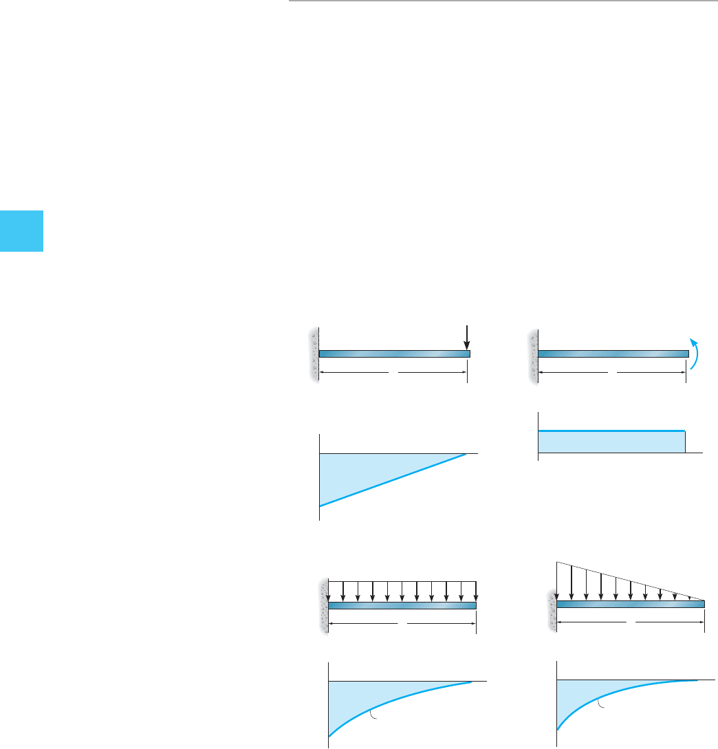
Most loadings on beams in structural analysis will be a combination of
the loadings shown in Fig. 4–20. Construction of the associated moment
diagrams has been discussed in Example 4–8. To understand how to use
P
L
M
PL
x
(a)
Fig. 4–20
M
0
L
M
x
(
b
)
M
0
L
L
M
x
(c)
w
0
parabolic curve
w
0
L
2
______
2
L
M
x
(d)
w
0
w
0
L
2
______
6
cubic curve

4.5 MOMENT DIAGRAMS CONSTRUCTED BY THE METHOD OF SUPERPOSITION 169
4
the method of superposition to construct the moment diagram consider
the simply supported beam at the top of Fig. 4–21a. Here the reactions
have been calculated and so the force system on the beam produces a zero
force and moment resultant.The moment diagram for this case is shown at
the top of Fig. 4–21b. Note that this same moment diagram is produced for
the cantilevered beam when it is subjected to the same statically equivalent
system of loads as the simply supported beam. Rather than considering all
the loads on this beam simultaneously when drawing the moment diagram,
we can instead superimpose the results of the loads acting separately on
the three cantilevered beams shown in Fig. 4–21a. Thus, if the moment
diagram for each cantilevered beam is drawn, Fig. 4–21b, the superposition
of these diagrams yields the resultant moment diagram for the simply
supported beam. For example, from each of the separate moment diagrams,
the moment at end A is as verified by the
top moment diagram in Fig. 4–21b. In some cases it is often easier to
construct and use a separate series of statically equivalent moment
diagrams for a beam, rather than construct the beam’s more complicated
“resultant” moment diagram.
M
A
=-200 - 300 + 500 = 0,
4 k/ft
A
300 kft
B
10 ft 10 ft
15 k 25 k
4 k/ft
10 ft
40 k
200 kft
ⴝ
ⴙ
10 ft
300 kft
300 kft
ⴙ
20 ft
500 kft
25 k
25 k
superposition of cantilevered beams
(
a
)
4 k/ft
A
300 kft
B
10 ft 10 ft
15 k
25 k
M (kft)
250
50
x(ft)
resultant moment diagram
M (kft)
200
ⴝ
ⴙ
x(ft)
M (kft)
x(ft)
ⴙ
300
M (kft)
x(ft)
500
superposition of associated moment diagrams
(b)
Fig. 4–21
