Helena Ramos. Guidelines for design of small hydropower plants
Подождите немного. Документ загружается.

Hydraulic Design of Small Power Plants
- 51 -
5.2.3- Sedimentation or desilting basin
A sedimentation basin allows settling fine particles in suspension that may wear
parts of the turbine and to decrease its efficiency and lifetime. The settling is due
to gravity action through the reduction of the flow velocity by increasing the
cross-section. Normally these basins are prismatic tanks, where the flow has a
main horizontal direction. The tank can be considered divided in four zones:
1- inlet zone;
2- settling zone;
3- outlet zone;
4- sludge storage zone.
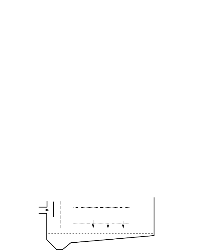
The inlet zone should assure a uniform flow velocity distribution by imposing
the flow through a perforated baffle. The settling zone allows the sedimentation
of the solid particles. Clean water is driven into the hydraulic conveyance system
through an outflow weir or orifice (Figure 5.11).
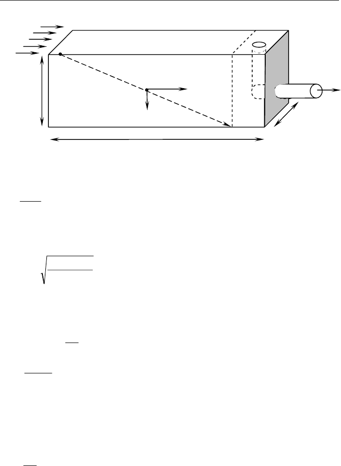
For design purposes, the solid particles are assumed as spherical shape, with a
uniform specific weight. The typical dimensions of the sedimentation (or a
desilting) basin are represented in Figure 5.12, for an inflow discharge Q at the
inlet of the basin with a depth D, a width W and a length L.
Fig. 5.11 – Different zones in a sedimentation basin.
Through each basin cross-section, the free-surface flow is supposed to be
horizontal and with a uniform velocity. Particles tend to settle to the bottom with
a fall velocity Vs. Normally, the mean diameter of the particles (D
50
) considered
admissible for small turbines is about 0.2 mm. This value will depend on each
turbine type (the turbine manufacturer should indicate the maximum allowable
particle dimension).
Settling zone
Target baffle
Q
Inlet zone
Sludge zone
Outflow weir
Clean wate
r
Outlet
zone
Inflow with
solids
Solids
Guidelines for design of SMALL HYDROPOWER PLANTS
- 52 -
Fig. 5.12 – Schematic sedimentation basin.
The flow velocity is dependent of the basin main dimensions:
D.W
Q
V = (5.11)
The sedimentation velocity can be obtained by the following equation:
R
50
C
)1d(D
61.3Vs
−
= (5.12)
where
d is the solid particle density (ratio between specific weight of the particle and
the water,
γ
γ
p
d =
, normally for silt type d
≈
2.5); R
e
is the Reynolds number,
υ
=
50s
e
DV
R
, being υ the water viscosity
υ
=10
-6
m
2
/s.
Based on the design discharge (Q) and the sedimentation velocity (Vs) the
superficial area, As, necessary for settling particles of dimension greater than D
50
is obtained by
Vs
Q
As
= (5.13)
Q
Settling zone
Vs
V=Q/(WD)
Outlet
zone
D
L
W
Hydraulic Design of Small Power Plants
- 53 -
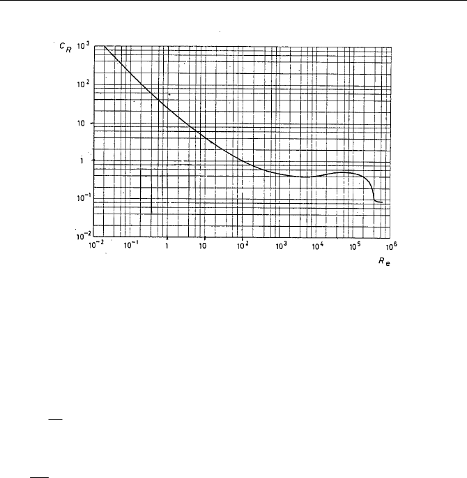
Fig. 5.13 – Spherical shape coefficient, C
R
, as a function of Reynolds number, R
e
(adapted from QUINTELA, 1981).
The sedimentation criterion requires that the scour time T
scour
of a particle must
be greater than the sedimentation time T
s
, (T
scour
≥ T
s
) in order to the particle be
sedimented.
V
L
T
scour
= (5.14)
Vs
D
T
s
=
(5.15)
In practice the basin behaviour will be different from the one predicted by the
theoretical calculation. One main factor that influences the basin behaviour is the
flow turbulence and the non-uniform horizontal velocity distribution. One way to
obviate this problem consists in increasing the superficial area, As, of the basin
or the width, W, and removing all angles or unnecessary singularities.
The width and the flow velocity must be controlled, in order to avoid the lift up
of settling particles (i.e. verification of the non-drag criterion). The equation
(5.16) gives the relation between the scour velocity and the geometry of the
sedimentation basin (ASCE/EPRI, 1989):
Guidelines for design of SMALL HYDROPOWER PLANTS
- 54 -
()
21
50
R
61
Hscour
8.304
D
1dCRK5.0V
−= (5.16)
with R
H
= hydraulic radius of the sedimentation basin,
D2W
D.W
R
H
+
=
, and K
the Gauckler-Manning-Strickler coefficient, for concrete basin K = 75 m
1/3
/s.
The methodology consists in set a value for W based on As, and define L. Then
D values will be arbitrated in order to verify that V
scour
is greater than mean flow
velocity, V.
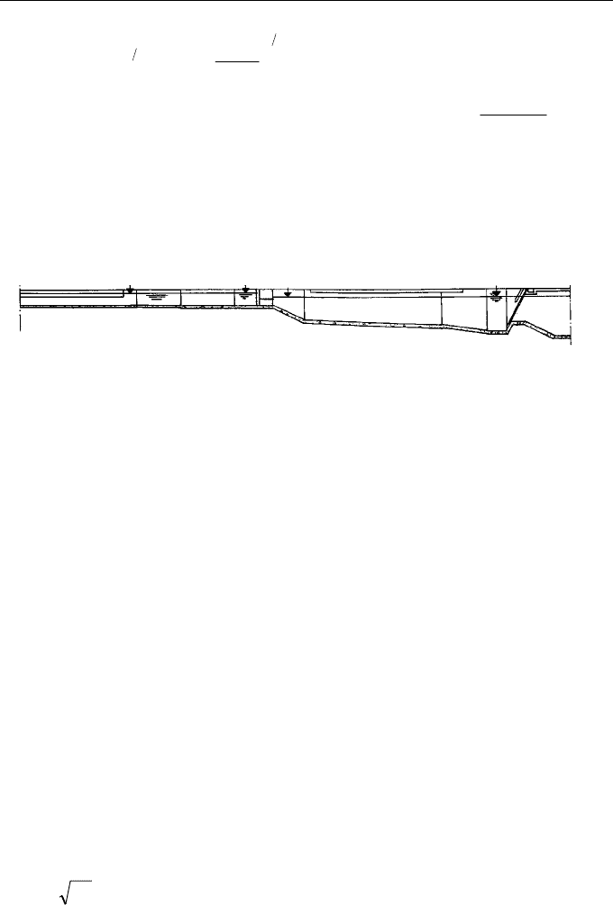
Fig. 5.14. –Scheme of a forebay.
The depth, D, can vary along the length of the basin, as showed in Figure 5.14.
Nevertheless the obtained D will be an average depth.
5.2.4- Weir
The weir crest (in this case it will also be the spillway) is, normally, located in
the middle of the low dam. Sometimes is convenient to install a gate in order to
increase the storage capacity. The full storage water level (FSWL) coincides with
spill crest because is the maximum capacity under normal operating conditions.
The weir will be designed for a discharge flow with a chosen return period (e.g.
100 years) and should also be verified for greater discharges, corresponding to
the maximum flood water level (MFWL).
The typical spillway profile is defined in order to have atmospheric pressure
along its surface for design conditions. For discharge verification (Q
max
>Q)
under-pressures along the spillway profile will be accepted, since the head is
greater than the design head (according to criteria based on Waterways
Experimental Station (WES) – Corps of Engineers, US).
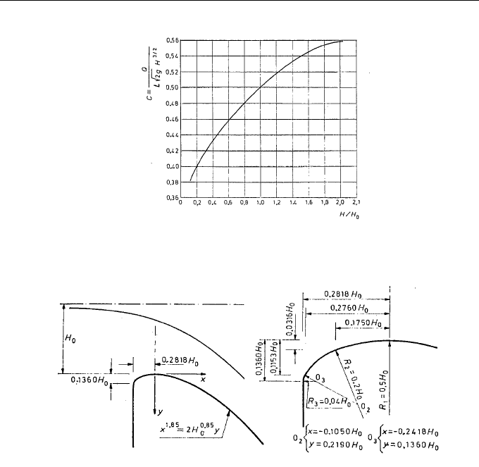
The general free-surface weir discharge law is given by
2/3
Hg2CLQ =
(5.17)
Forebay
Approach canal
Intake
Rac
k

Hydraulic Design of Small Power Plants
- 55 -
being:
Q = weir discharge (m
3
/s);
C = discharge coefficient (-);
L = weir width (m);
H
o
= head over the spillway crest (m);
g = gravity acceleration (m/s
2
).
The discharge coefficient for a WES type weir is around C = 0.50, depending on
the head value (e.g. is superior to 0.50 for heads greater than design one and
conversely for lower heads).
Figure 5.15 shows the variation of discharge coefficient with the head. Should
lateral entrance wing walls exist in order to avoid flow lateral contraction.
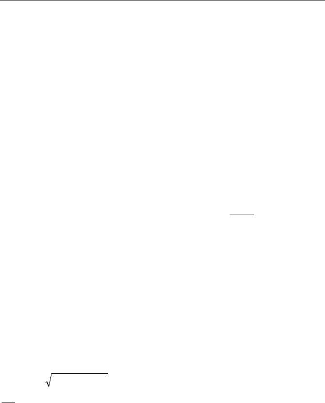
The design head is obtained by equation (5.17) based on the design flood
discharge. The analytic definition of the spillway profile is obtained by the
following equation (WES profile):
85.0
o
85.1
H2
x
y =
(5.18)
The connection curve between the vertical upstream wall and the spillway profile
is obtained by an ellipse or by several arcs of curves according to Figure 5.16.
For verification discharge (Q
max
>Q), the spillway profile will operate with a
pressure lower than atmospheric one and the discharge coefficient will increase.
For a smaller discharge (Q
min
<Q) over-pressures (greater than atmospheric
pressure) will occur along the spillway profile with a smaller discharge
coefficient.
In order to avoid flow separation and cavitation risk for higher heads, the
following design criteria should be obeyed (LENCASTRE, 1987):
H
max
/Ho ≤ 1.4
According to the value accepted for the maximum or verification head (H
max
) the
wing lateral walls are fixed with a certain freeboard (e.g. 1 m at least) above the
MFWL.
Guidelines for design of SMALL HYDROPOWER PLANTS
- 56 -
Fig. 5.15 - Discharge variation of a WES spillway as a function of H/H
o
(ABECASIS, 1977).
Fig. 5.16 - Spillway profile for the design head (H
o
)
(CORPS OF ENGINEERS, WES referred in QUINTELA, 1981).
In small dams it is very acceptable to choose a stepped spillway where the
downstream side is build with steps, where the flow can dissipate a certain
amount energy (see Figure 3.6 - at bottom). The construction cost can also be
cheaper. When the available space for locating the spillway is limited a labyrinth
or semicircular solutions should be considered, in order to obtain higher
discharge.
A dissipation structure should be provided downstream the dam if the
geotechnical conditions are not strong enough.
Hydraulic Design of Small Power Plants
- 57 -
5.3- Sluice bottom outlet
To empty the reservoir the dam should be provided with a sluice bottom
discharge. To obtain the emptying law of a dam sluice bottom outlet is necessary
to define the hydraulic conveyance system characteristics, namely singular loss
coefficients, the roughness and the cross section. Through the energy equation
between reservoir level, Hr, and the axe of the outlet works, Hd, (flow into the
atmosphere):
HdHHr =∆−
(5.19)
where
Hr = is the upstream water level;
∆H = is the total head losses (as a function of Q - see 5.4 - Conveyance System);
Hd = outlet works axe added by kinetic outlet head
=
2
2
gA2
Q
, where A is the
outlet cross-section.
It is important to know the velocity value at outlet, in order to prevent eventual
energy dissipation structure (e.g. impact blocks), as well as to predict the safe
height of wing walls to direct the flow towards the river.
The bottom discharge will allow the total or partial reservoir emptying. To
estimate the emptying duration, it is common to consider a null inflow discharge
and the full storage water level (FSWL). Based on the discharge law for sluice
bottom outlet and on mass flow balance equation:
)HHr(g2SQ
refoutlet
−ξ=
outletinlet
QQ
dt
d
−=
∀
(5.20)
where Q
inlet
is the inlet discharge into the reservoir (= 0 m
3
/s), Q
outlet
is the outlet
discharge from the reservoir (m
3
/s) and
∀
the volume of the reservoir (m
3
).
The differential equation can be integrated by a finite difference technique in
order to obtain the total duration of the reservoir emptying.
Guidelines for design of SMALL HYDROPOWER PLANTS
- 58 -
5.4- Conveyance system
5.4.1- General layout
The conveyance system includes all elements designed to water transport from
the intake to the powerhouse. The conveyance layout can be composed either by
pressure galleries or pipes or by a mixed system composed by free-surface canals
and pressurised pipes. The layout of the conveyance system depends on several
factors according to the following remarks:
•
Analysis of different sites for low dam and powerhouse installation
and conveyance layout alternatives to seek for the economic net
head, the minimum length that involves smaller volumes of
excavation, and land volume to replace. All alternatives should have
good access and the concern about minimisation of expropriating,
must be performed. The selection of the more adequate final
proposes will be based on technical, economic and social
considerations.
•
The cross-section of the hydraulic system (e.g. characterised by a
diameter) should be the most economic in order to attend the annual
average energy production and the costs for conveyance system
installation.
•
Definition of all system accessories and components along the total
conveyance system and the more correct place to install them.
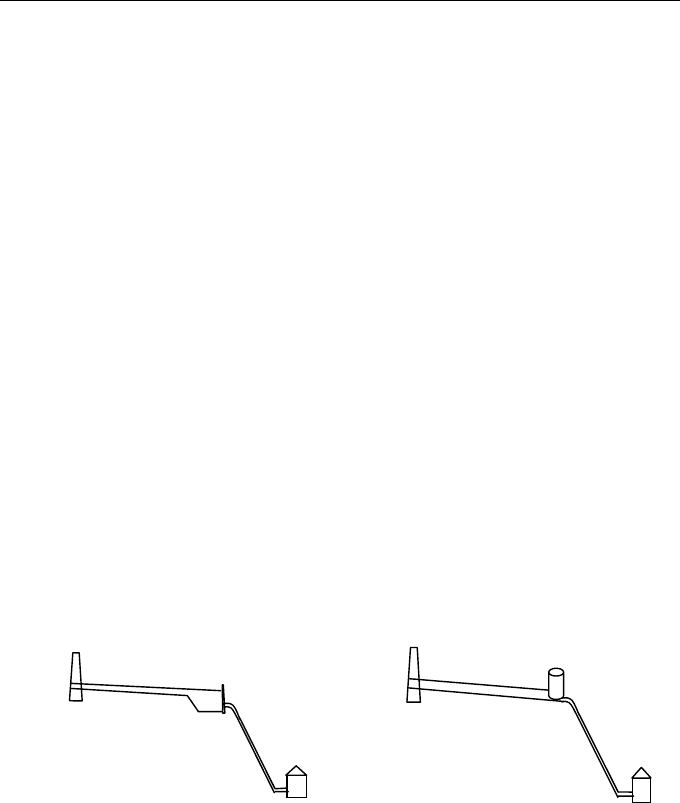
Fig. 5.17 – Schematic layouts for the hydraulic system.
Site selection for the headwork (e.g. a small dam and the intake structure) and
the powerhouse should be carried out on the basis of topographical and
geological conditions and on site visits. The main factors to be considered in the
alignment of canals or low pressure pipes are:
•
If a reach of a pipe can gain at least 2% of head, H, the experience
shows it is economically feasible.
Small
dam
Canal
Forebay
Penstock
Powerhouse
Small
dam
Low pressure
pipe
Surge tank
Penstock
Powerhouse

Hydraulic Design of Small Power Plants
- 59 -
• A long canal could be unfeasible geomorphologically because the
need to overcome side streams and gullies that imposes the
construction of crossing structures, such as inverted siphon.
Potential slides should be properly considered.
•
River bends associated to sound geological conditions are generally
favourable to a straight tunnel within combined with canals or low-
pressure pipes.
•
Plastic pipes could be considered but there are limitations of
allowable available diameters, sunlight effects, pressures, and
temperature variations. These factors impose that the plastic pipes
should be buried or covered.
These constraints should be studied comparatively in order to obtain the best
solution.
For a total pressurised circuit with pipes following the land profile, a blow-off
valve should be installed at the lowest point allowing the pipe emptying and an
air-valve should be installed at high points of the pipeline to avoid it collapsing
or buckling associated to air pressure problems. The highest point of the conduit
should be positioned below the lowest hydraulic gradient line under extreme
operating conditions (Figure 5.18).
Fig. 5.18 – Example of the hydraulic grade line and penstock profile.
Due to turbine discharge variations or turbine guide vane manoeuvres the
pressure will vary, along the penstock, with the time. The maximum and
Hmax – maximum upsurge
Purge or
blow-off
valves
Natural land
p
rofile
Penstock profile
Powerhouse
Hydraulic grade lines
Air valves
Hmin – minimum downsurge
Ho – steady state regime
Guidelines for design of SMALL HYDROPOWER PLANTS
- 60 -
minimum piezometric head envelopes should be indicated and compared with
the penstock profile and with the pipe resistance. The control of both the
maximum and minimum transient pressure variations is one of the design
objectives.
5.4.2- Head losses and net head
The net head, H
o
, is one of the most important parameter for a feasibility analysis
and design of a hydroelectric system. The material, the cross-section and the
length of the penstock will influence the headloss. Net head calculation will be
based on the knowledge of the gross head (H
g
- geometric water level or the
difference between water level at the intake (Z
u
) and the water level at the
tailrace (Z
d
)- for reaction turbines or the nozzle axe – for action turbines (in
particular for Pelton)) and all head losses (friction and all singularities losses,
∆Hi, along the hydraulic conveyance system). The headloss will be a function of
the diverted discharge.
∑
∆−−=
i
iduo
HZZH (5.21)
The design head is used to define the design power output of a turbine (typically
the maximum power output for the best efficiency head). For a hydropower
station with a high head scheme (e.g. with long penstock), the variation in the
water level can have less effect on power output than, perhaps, the variation of
the head losses with the discharge.
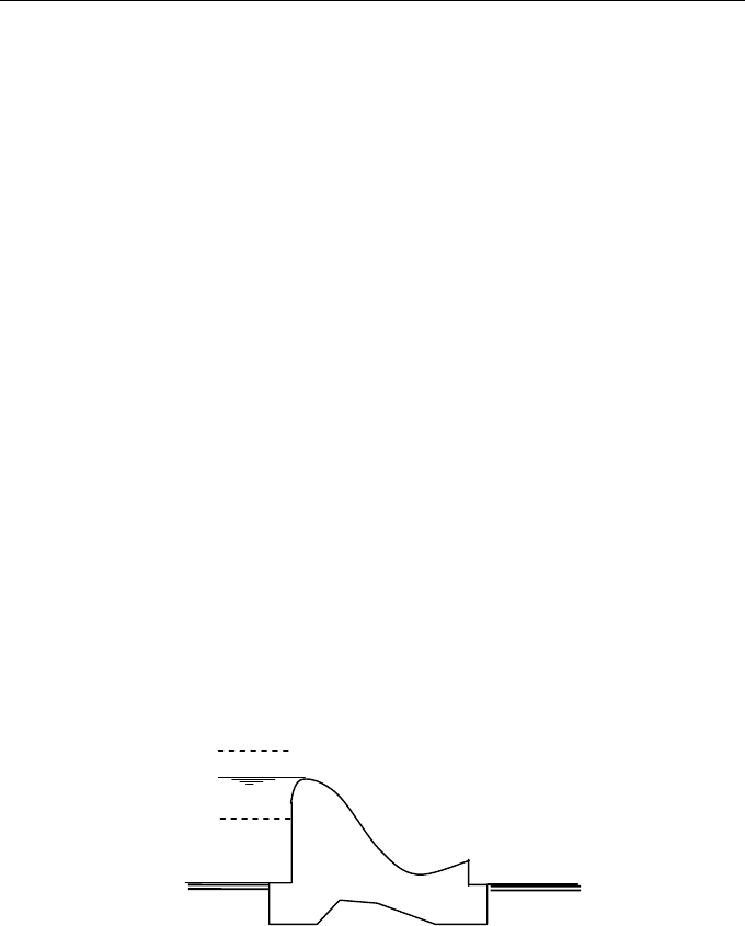
Fig. 5.19 – Water levels at the reservoir.
When the reservoir water level change during the powerplant operation, a
maximum water level may appear when the weir discharges the maximum flood
(MFWL - maximum flood water level). The crest of the weir gives the full
MFWL
FSWL
MEWL
Spillway
Dam