Graebel W.P. Advanced Fluid Mechanics
Подождите немного. Документ загружается.

94 Irrotational Two-Dimensional Flows
a
d
c
z plane z ′ plane
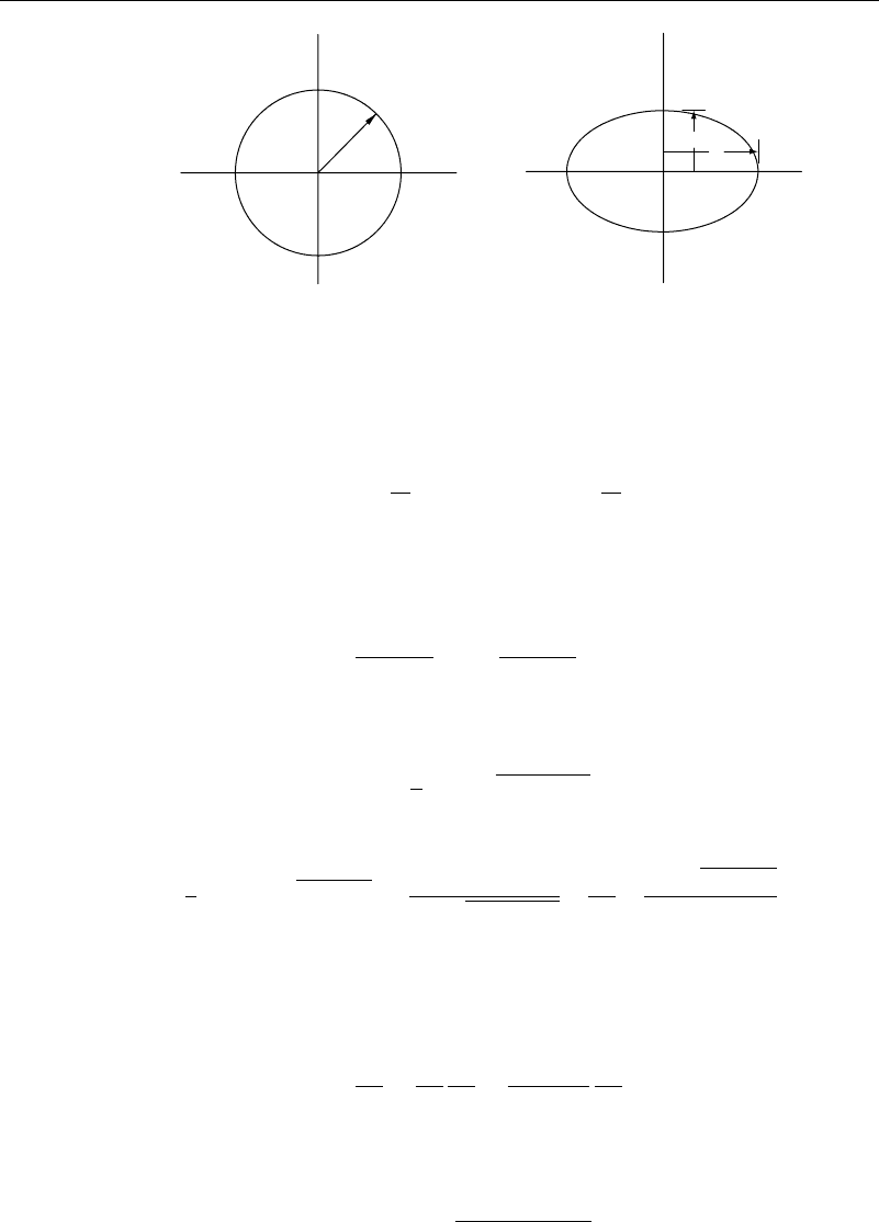
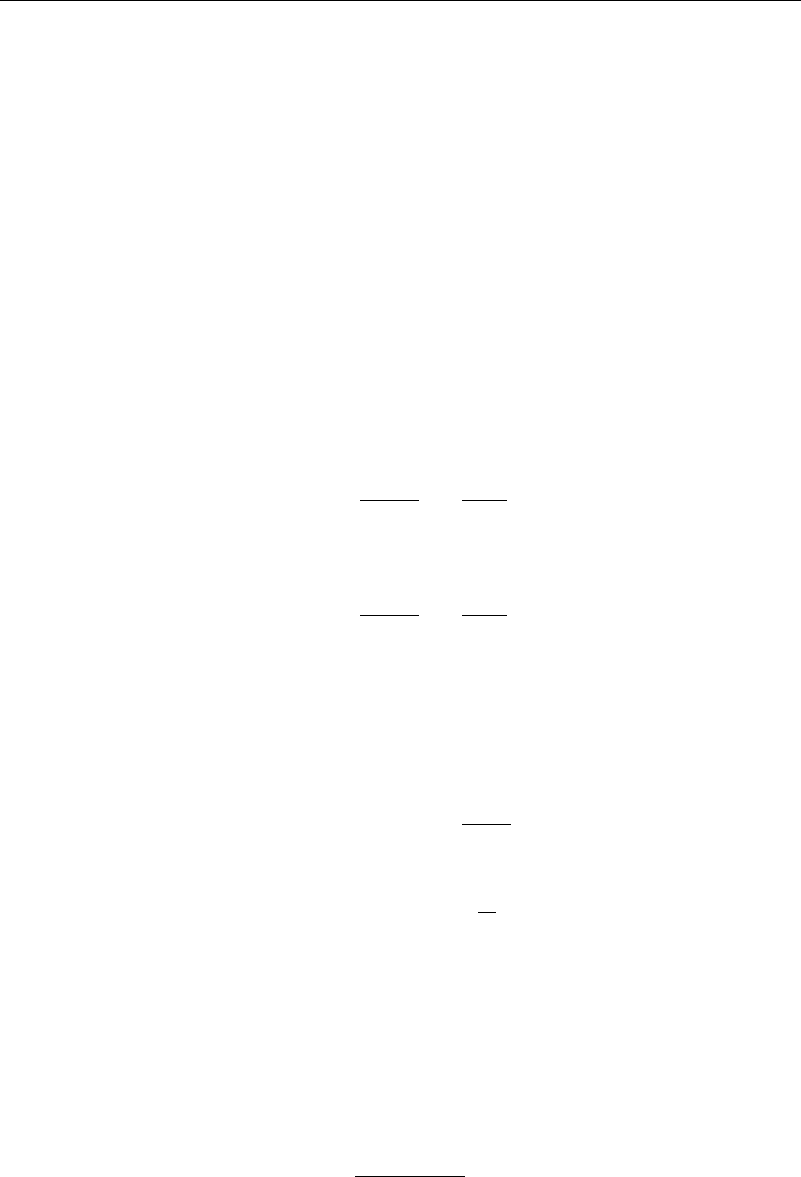
Figure 3.3.1 Ellipse in a uniform stream—transformations
To see what the Joukowski transformation does, let z =ae
i
in equation (3.3.1) and
then divide the resulting expression into real and imaginary parts. We then have
x
=
a +
b
2
a
cos y
=
a −
b
2
a
sin (3.3.2)
and the circle of radius a in the z plane is seen to have been transformed into an ellipse
in the z
plane with semimajor axis c = a +b
2
/a and semiminor axis d = a −b
2
/a
(Figure 3.3.1). Upon elimination of the equation of the ellipse is found to be given by
x
a +b
2
/a
2
+
y
a −b
2
/a
2
=1 (3.3.3)
With this knowledge in hand, the flow past an ellipse can be computed.
The direct approach would be to solve equation (3.3.1) for z, obtaining
z =
1
2
z
+
z
2
−4b
2
(3.3.4)
and then substituting this into equation (3.2.1), obtaining
w =
1
2
U
∗
z
+
z
2
−4b
2
+
2Ua
2
z
+
z
2
−4b
2
+
i
2
ln
z
+
√
z
2
−4b
2
2a
(3.3.5)
The velocity is then found by forming dw/dz
from equation (3.3.5).
A slightly less direct approach—but with some advantages—would be to compute
the z coordinate corresponding to a point z
by use of equation (3.3.4). The velocity can
then be found using this with equation (3.2.2) and the chain rule of calculus to be
dw
dz
=
dw
dz
dz
dz
=
1
1−b
2
/z
2
dw
dz
(3.3.6)
From equation (3.3.6) it is easy to see that the velocity is infinite at the points z =±b.
Using the expressions for the semimajor and -minor axes, the parameter b in the
transformation is given by
b = a
c −d/c +d (3.3.7)
The points of infinite velocity in equation (3.3.6) lie inside the ellipse unless d = 0,
in which case they lie on the ellipse. For d = 0 the ellipse degenerates to a flat plate,
3.4 The Joukowski Airfoil 95
and the velocity is infinite at both endpoints of the plate, unless of course the plate is
aligned parallel to the uniform stream.
Notice that the possibility exists in the preceding analysis that, at a point where
the denominator in equation (3.3.6) becomes zero, dw/dz also is zero. We will use this
when we discuss airfoils.
3.4 The Joukowski Airfoil
The flow past an ellipse provides the clue needed to generate an airfoil shape. The
principle characteristic of an airfoil is that it has a sharp trailing edge. At that point, the
airfoil has a discontinuity in slope, and the mapping will not be conformal. To obtain
such a shape, Joukowski proposed the following sequence of transformations.
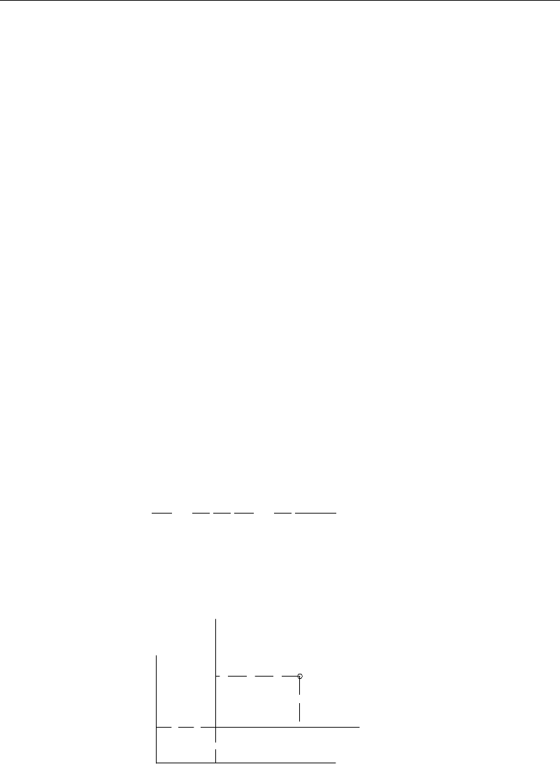
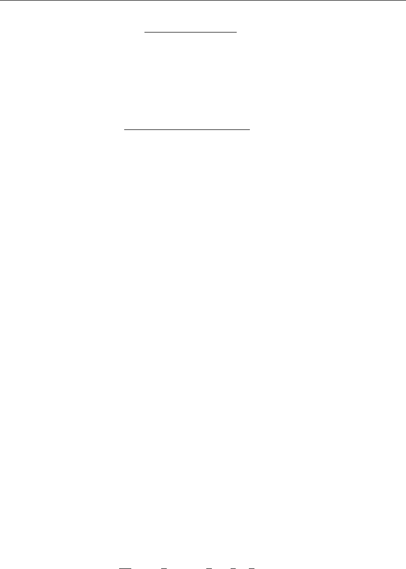
The circle in the z plane is first translated in a new coordinate system with origin
at z
c
(Figure 3.4.1) as given by
z
=z +z
c
where z
c
=x
c
+iy
c
and x
2
c
+y
2
c
≤a
2
(3.4.1)
Under this translation the circle z = ae
i
in the z plane will still be a circle in the z
plane, where it now satisfies the equation x
−x
c
2
+y
−y
c
2
=a
2
and has its center
at z
c
. The stagnation points originally at z
DSP
=ae
i−
and z
USP
=ae
i++
in the z
plane are now at
z
DSP
=z
c
+ae
i−
and z
USP
=z
c
+ae
i++
(3.4.2)
in the z
plane, as shown in Figure 3.4.2.
The z
transformation is next followed by the Joukowski transformation
z
=z
+b
2
/z
(3.4.3)
Here b is a real number. Since
dw
dz
=
dw
dz
dz
dz
dz
dz
=
dw
dz
z
2
z
2
−b
2
(3.4.4)
it is seen that the velocity in the z
plane will be infinite at the points z
=±b unless
one of these points coincides with a stagnation point in the z plane. Therefore, to make
the transformed circle into an airfoil shape, the first stagnation point in equation (3.4.2)
(x,y )
x
c
y
c
y ′
x
′
x
y
z and z
′ planes
′
′
Figure 3.4.1 Joukowsky transformation—z and z
planes
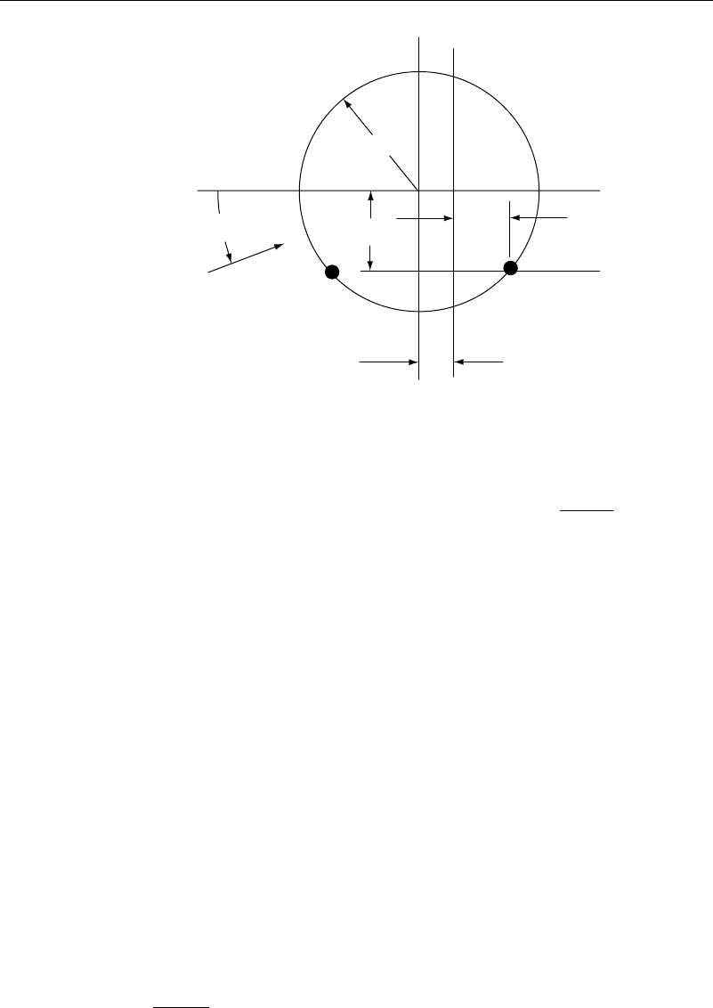
96 Irrotational Two-Dimensional Flows
USP
DSP
α
U
x
′
a
x
c
y
c
b
y
′
y
x
′
′
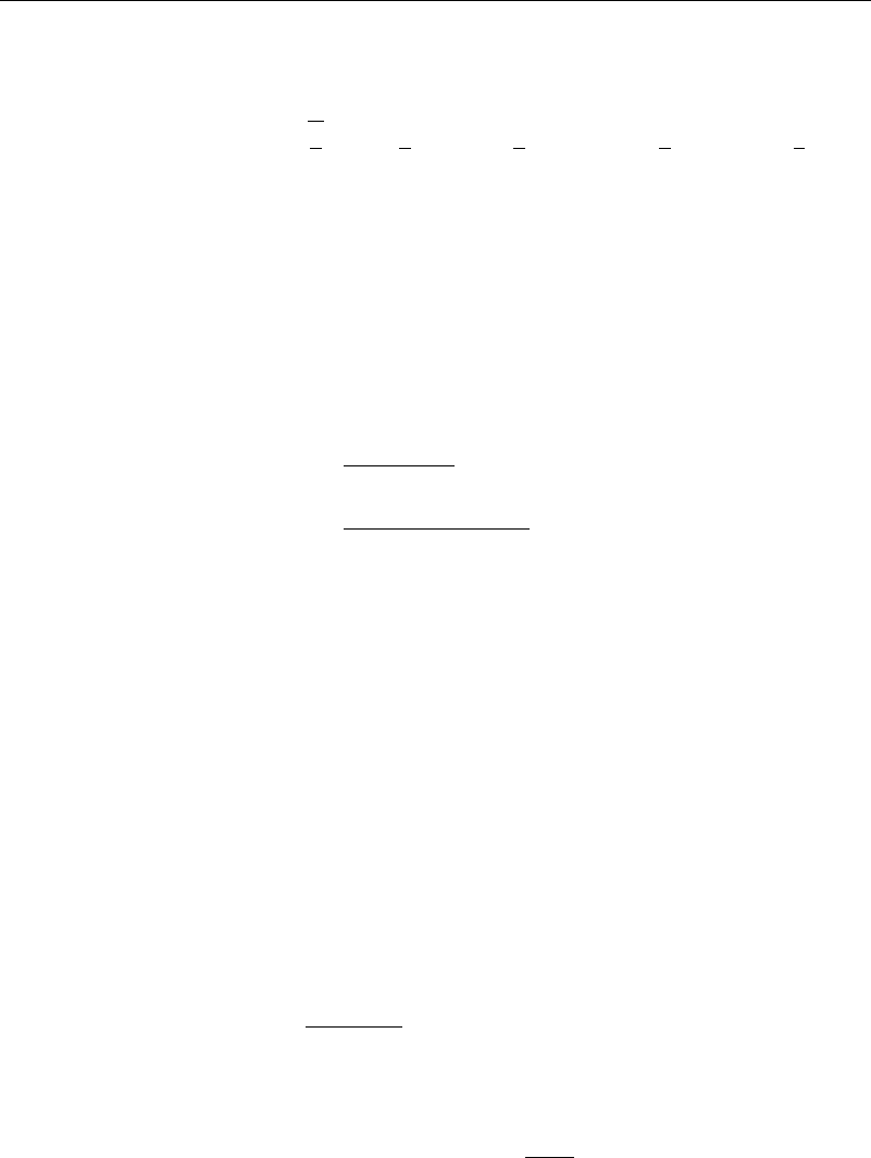
Figure 3.4.2 Joukowsky airfoil—z and z
planes
must lie on the circle and be where z
=+b. This will give a sharp trailing edge, and the
mapping of the cylinder to the airfoil will not be conformal at that point. This results in
y
c
=−asin − and b =x
c
+a cos − =x
c
+
a
2
−y
2
c
(3.4.5)
Further, require for later purposes that the point z
=−b 0 does not lie outside
the circle, this condition being satisfied provided that
b +x
c
2
+y
2
c
<a
2
(3.4.6)
This means that, except inside the body, the only possible place where the velocity can
be singular is at z
=b. Satisfaction of both parts of equation (3.4.5) means that x
c
≤0.
Investigating the transformation further, note that on the circle in the z
plane, at
the trailing edge/stagnation point the angle the surface turns through is 2 (or zero),
whereas on the airfoil the corresponding angle is . The reason that the requirement
was made that z
=−b must not lie outside the circle is that we wanted to ensure that
no singularities were introduced into the flow, only inside the circle.
The shape of the airfoils that this family of transformations has generated can now
be found. The following outlines the approach:
1. Specify U , the attack angle and the coordinates of the center of the translated
circle x
c
and y
c
. The latter is to be done such that x
c
< 0 and x
2
c
+y
2
c
≤a
2
. (The
choice of a is in fact arbitrary, representing a scaling of the coordinate system,
and could just as well be taken as unity. The same is true for U, which scales
the velocity.) The parameter x
c
controls the airfoil thickness, while y
c
controls
its camber.
2. Compute b , and .: From equation (3.4.5), = +sin
−1
y
c
/a b = x
c
+
a
2
−y
2
c
. From equation (3.2.7)
=4a
U
sin
3.4 The Joukowski Airfoil 97
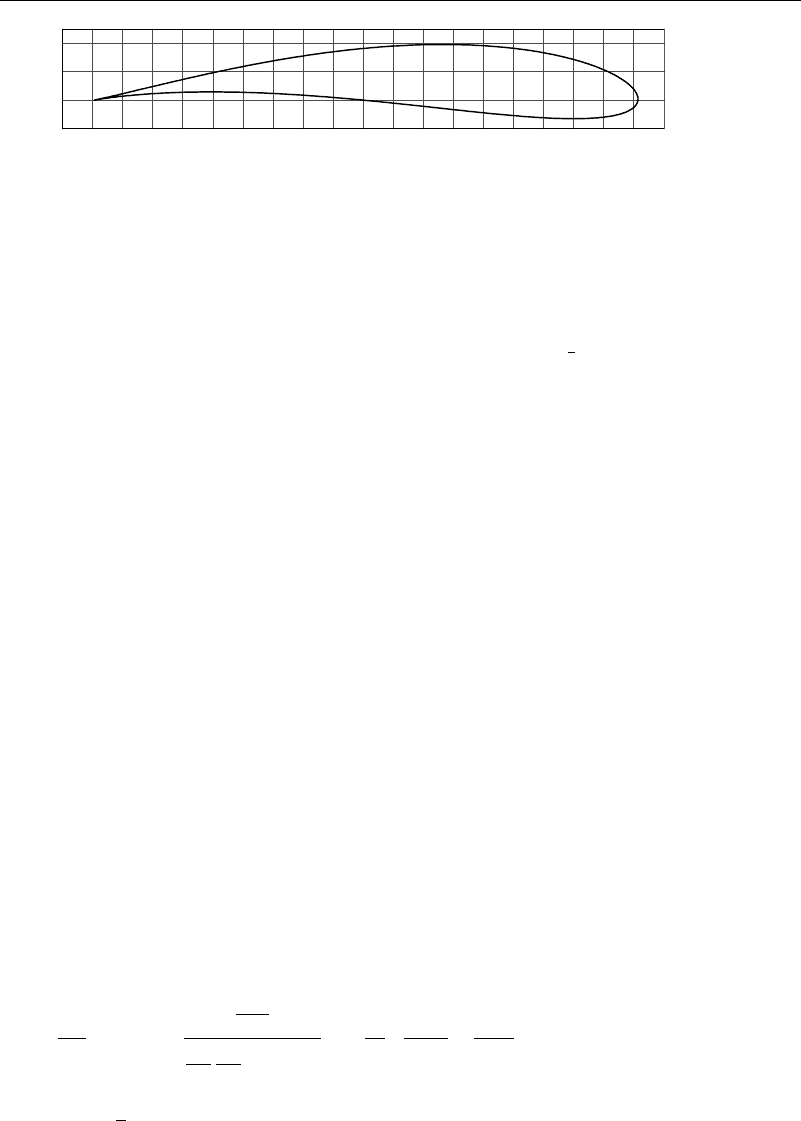
y
″
x
″
Figure 3.4.3 Joukowsky airfoil shape
3. Choose an arbitrary point z = ae
i
on the circle by selecting a value for .
Compute the corresponding transformed position of this point on the airfoil using
equations (3.4.1) and (3.4.3).
4. To find the velocity and pressure on the airfoil, use equation (3.4.4) for the veloc-
ity and then compute the pressure coefficient according to C
p
=
1
2
1−
U/U
2
.
5. Repeat steps 3 and 4 for a number of values of to generate the airfoil shape
and the pressure distribution.
6. Repeat steps 1 through 5 for various values of x
c
and y
c
to see the effect of
these parameters on airfoil shape.
Figure 3.4.3 shows a typical airfoil generated by this procedure. Here
U
=1=0A= 1x
c
=−01y
c
=01
In the beginning of the analysis, the vortex was somewhat arbitrarily added to the
flow. Its presence is an absolute necessity if a lift force is to be present. How, then,
does the flow introduce circulation?
In the case of the circular cylinder, circulation would have to be added artificially,
either by rotating the cylinder (the Magnus effect) and letting viscosity and the no-slip
condition introduce the swirl or by forcing the position of the stagnation points either
by the addition of a small flap where the trailing edge would be (Thwaite’s flap)orby
some other means to control the pressure on the boundary. In the case of the airfoil,
note that our theory predicts an infinite velocity at the trailing edge unless dw/dz = 0
at that point. In fact, unless we impose the condition dw/dz = 0 at the trailing edge,
the velocity there is not only infinite, but it turns through 180 degrees in zero distance.
A real fluid cannot do this because it implies infinite acceleration requiring infinite force.
Kutta proposed that the circulation will adjust itself so that both the infinite velocity
and the sharp turn in the flow at the trailing edge are avoided. At this stage both
numerator and denominator in equation (3.4.4) are zero, meaning that dw/dz
is of the
form zero over zero. To resolve the value of the true speed at the trailing edge, use
L’Hospital’s rule, in the form
dw
dz
= lim
z
→b
⎡
⎢
⎢
⎣
z
2
d
2
w
dz
2
dz
dz
d
dz
z
2
−b
2
⎤
⎥
⎥
⎦
=
b
2
2b
2a
2
U
z
3
−
i
2z
2
z=ae
−i+
=
b
a
U
e
2i+
cos
(3.4.7)
This tells us that the body slope at the trailing edge is turned an angle of 2 from the
attack angle .
98 Irrotational Two-Dimensional Flows
Kutta’s hypothesis (usually referred to as a Kutta condition) gives a very good
value for the circulation on a Joukowski airfoil, as has been verified in a series of
tests (National Advisory Committee for Aeronautics Technical Report number 391 and
Technical Memorandums 422 and 768). Joukowski airfoils do have very good stalling
behavior and can achieve angles of attack as high as 30 degrees with only a slight
drop in lift. They have the disadvantage of having a rather high drag coefficient, and
the very thin, sharp trailing edge makes their construction very difficult.
3.5 Kármán-Trefftz and Jones-McWilliams Airfoils
There have been several variations of the Joukowski airfoil that add several helpful
features. One, proposed by von Kármán and Trefftz, eliminates the disadvantage of the
thin trailing edge.
Transformation equation (3.4.1) can be written in the equivalent forms
z
+2b = z
+b
2
/z
z
−2b = z
−b
2
/z
Taking the ratio of these, the Joukowski transformation can therefore be written in
the form
z
+2b
z
−2b
=
z
+b
z
−b
2
(3.5.1)
Von Kármán and Trefftz suggested replacing the Joukowski transformation with the
alternate transformation
z
+2b
z
−2b
=
z
+b
z
−b
n
(3.5.2)
The trailing edge then has an inside angle of 2 −n, rather than zero. The details of
the shape can be carried out in a manner similar to the Joukowski airfoil, with one more
variable n available to the designer.
A second variation of the Joukowski airfoil was proposed by R. T. Jones and
R. McWilliams in a pamphlet distributed at an Oshkosh Air Show. They also start with
equation (3.4.1) but then follow it with the two transformations
z
=z
−
z
−
(3.5.3)
and
z
=z
+
b
2
z
(3.5.4)
where is a complex number and is real. Carrying through an analysis similar to
what we did for the Joukowski profile, it can be shown using the same general analysis
as for the Joukowski transformation that
=x
T
−bx
T
− −y
T
2
+iy
T
2x
T
− −b (3.5.5)
where x
T
y
T
is the location of the trailing edge in the z
plane.
It is convenient to set b, a scale factor, arbitrarily to 1. The parameters
x
c
y
c
x
T
y
T
are then set by the designer. The parameter is determined by equa-
tion (3.5.5) subject to the inequality
−b ±
+b
2
+4 −2x
c
+iy
c
< 2a (3.5.6)
3.6 NACA Airfoils 99
and the parameter a is determined by
a =
x
T
−x
c
2
+y
T
−y
c
2
(3.5.7)
The circulation is then found from
=4aU B (3.5.8a)
with B given by
B =
x
T
−x
c
sin −y
T
−y
cos
a
. (3.5.8b)
With a careful selection of the parameters, Jones and McWilliams have generated airfoils
with the properties of the NACA 6 series, the 747 series, the Clark Y, and the G-387.
3.6 NACA Airfoils
Early airfoil designs by Eiffel, the Wright brothers, and many others were largely
the result of intuition and trial and error, although the Wright brothers did utilize a
crude wind tunnel and were well read as to the aerodynamic theory of their day.
During World War I, Prandtl at Gottingen, Germany, started to put these designs
on a firmer basis, and efficient airfoils such as the Gottingen 398 and the Clark Y
were developed. These airfoil shapes, or extensions of them, were utilized almost
exclusively during the 1920s and 1930s. In the 1930s, the NACA (National Advisory
Committee for Aeronautics, which later became NASA, the National Aeronautics and
Space Administration) started a comprehensive and systematic development program
that used both theory and experiment. They were able to separate out the effects of
camber and thickness distribution and also carried out experiments at higher Reynolds
numbers than had previously been possible.
Airfoil shapes are generally given by specifying many coordinate points on the
surface of the foil. The effects of camber and thickness can be separated by writing
x
U
=x
c
−y
t
sin (3.6.1a)
y
U
=y
c
+y
t
cos (3.6.1b)
on the upper surface of the foil, and
x
L
=x
c
+y
t
sin (3.6.1c)
y
L
=y
c
−y
t
cos (3.6.1d )
on the lower surface. Here x
c
y
c
are the coordinates of a point on the mean line, tan
is the slope of the mean line, and y
t
is the half-thickness. Mean lines are frequently
designed to have specific load distributions. For example, the following mean line
equation has constant loading over the chord (Abbott and von Doenhoff, pages 74 and
75, 1959):
y =−
c
Li
4
1−
x
c
ln
1−
x
c
+
x
c
ln
x
c
(3.6.2)
where c
Li
= 2 /U is the circulation per unit chord length, and U is the free stream
velocity.
100 Irrotational Two-Dimensional Flows
For two famous series of airfoils, the NACA four-digit and five-digit series, the
shapes are defined completely by formulae. In the four-digit series, the thickness is
given by
y
t
=5y
max
02969
x
c
−0126
x
c
+03537
x
c
2
+028431
x
c
3
−01015
x
c
4
(3.6.3)
where y
max
is the maximum value of the half-thickness, and c is the chord length. Near
the leading edge, neglecting all terms on the right-hand side of equation (3.6.3) beyond
the first, the foil is approximately given by the parabola y
t
/y
max
2
≈220374x/c. The
local radius of curvature at the leading edge is thus
R
LE
≈110187 y
2
max
/c (3.6.4)
The mean lines for the airfoils of this series are given by
y
c
=
m2px −x
2
p
2
for 0 ≤ x ≤p
=
mc −xx −2p +c
c −p
2
for p ≤ x ≤c
(3.6.5)
where m is the maximum camber (distance of the mean line from the chord line), and
p is the chordwise location of the maximum camber point.
The numbering system for this series is based on the foil shape. The first integer
is 100 m/c, the second integer is 10 p/c, and the third and fourth are 100 y
max
/c. Thus,
for an NACA 2415 foil, we have
m/c = 002 p/c = 0 4y
max
/c = 015 (3.6.6)
Foils with numbers NACA 00xx are symmetrical—that is, their mean and chord lines
coincide.
For the four-digit series, tests show that the maximum lift coefficient increases as
the position of maximum camber is shifted forward from midchord. The mean lines
for the four-digit series were not suitable for forward positions of maximum camber,
so the five-digit series was introduced. For the five-digit series, the thickness is given
by equation (3.6.3) and the mean lines by
y
c
=kx
3
−3mx
2
+m
2
x3−m/c for 0 ≤x ≤m
=
km
3
c −x
c
for m ≤x ≤c.
(3.6.7)
where k originally was calculated to give a design lift coefficient of 0.3, and m determines
where the maximum camber points occur. Differentiating equation (3.6.7), the maximum
camber points are found to occur at
x
MC
=m1 −
m/3c (3.6.8)
The numbering system for the five-digit series is based on a combination of foil shape
and aerodynamic characteristics. The first integer is 6 66667·C
L
, where C
L
is the design
lift coefficient. The second and third integers are 200 ·x
MC
/c, and the fourth and fifth
are 100 ·y
max
/c, where y
max
is the maximum thickness. Thus, an NACA 23012 wing
3.7 Lifting Line Theory 101
section has a design lift coefficient of 0.3, a maximum camber at 0.15 of the chord
length, and y
max
/c = 012.
Details of these series and others are given in Abbott and van Doenhoff (1959).
This book includes a good discussion of airfoil theory along with data on lift, drag,
and moment coefficients. Modern airfoils generally have more complicated shapes than
given by the NACA four- and five-digit series. Their shapes are usually given in tabular
form rather than by formulae.
3.7 Lifting Line Theory
At this point in the discussion there is a good bit of theory on foils of infinite span and
also information on test data on a large number of foil shapes. All good things come
to an end, however, including airplane wings, turbine blades, and vorticity lines (recall
that the last, however, do not end in the interior of the fluid). How, then, does the body
of two-dimensional knowledge fit into a three-dimensional world?
Suppose for example that a wing is to be designed and that the lift coefficient
distribution on the wing is given. This is a good starting point in the design process, as
the local value of the lift coefficient gives the load on the wing at that point, and this
load is intimately connected to the structural requirements of the wing. From the lift
coefficient, previous results for the Joukowski airfoil give the circulation distribution.
If a very simple wing design is used where the circulation is constant along the
span, in the interior of the wing, the portion of the vortex line along the span would
simply be a straight line. This portion of the vortex is called the bound vortex, since
it is bound to the wing. When this vortex line reaches the wing tips, it leaves the
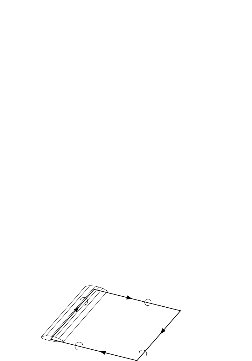
wing and is convected rearward with the flow. Considering the situation where the
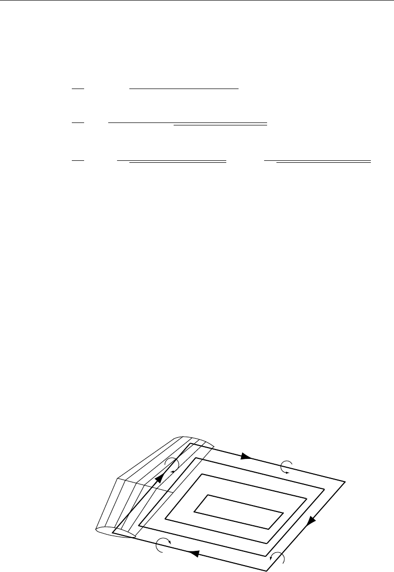
flow starts from rest, the vortex line for this case will be (approximately) a flat, closed
rectangle, consisting of the bound vortex, the tip vortices, and the starting vortices,as
shown in Figure 3.7.1. The length of this rectangle increases with time, as the starting
vortices move away from the wing. (The tip vortices can frequently be seen from an
airplane window. Because of the high rotational speeds at their core, the pressure there
is lowered. Water vapor can then condense, and flow visualization occurs.) The vortex
line is thus closed, so the requirement that a vortex line can neither originate nor end in
the fluid is met. When the starting vortex is very far away (at infinity), the pattern we
have described is called a horseshoe vortex.
Bound vortex
Tip vortex
Tip vortex
Starting vortex
Figure 3.7.1 Wingtip, boundary, and starting vortices
102 Irrotational Two-Dimensional Flows
Recalling that a doublet distribution is equivalent to a vortex sheet, with the local
vorticity being proportional to the change of the doublet strength, the velocity potential
for the vorticity associated with a finite wing can be found readily. Since we want
vorticity only on the boundaries of our rectangle, a constant-strength doublet facing
normal to the x-y plane is sufficient. This results in
=
4
s
−s
d
L
x
a
zd
x −
2
+y −
2
+z
2
3/2
=
4
s
−s
z −x
−y
2
+z
2
−x
2
+y −
2
+z
2
L
x
a
d
=
4
tan
−1
−yx −x
a
z
x −x
a
2
+ −y
2
+z
2
− tan
−1
−yx −L
z
x −L
2
+ −y
2
+z
2
s
−s
(3.7.1)
From Figure 3.7.1, and with the help of the right-hand rule of vectors, it is seen that the
effect of this vortex rectangle is to induce a downward velocity in the interior, called the
downwash. The downwash in turn contributes a drag to the wing, called the induced drag.
If the circulation distribution is not constant, such as for tapered wings, this pattern
is repeated, with each point in change in the circulation acting (weakly) as a wing tip.
Thus, the vorticity pattern might be as in Figure 3.7.2. The velocity potential for such
a pattern could be generated by including the effects of variable inside the original
integral in equation (3.7.1). The integration involved in such a procedure would very
quickly overtax our calculus skills!
The preceding procedure reduces the wing to a line. It was originated by Prandtl
(1921) and is called lifting-line theory. The vortex-lattice method is a more detailed
procedure than a lifting line theory. It gives some geometry to the wing and is similar
to the panel method introduced earlier. The constant-strength doublet panels with which
we might expect to cover our wing (with some mathematical difficulties) are instead
replaced by a series of horseshoe vortices as we just saw. Experience suggests that
the best results are found by placing the bound vortex portion of the horseshoe at the
quarter-chord point. Computer programs to calculate the resulting velocities are closely
related to our panel programs. (See, for instance, Moran (1984) for more details.)
Figure 3.7.2 Vortex pattern for a tapered wing
3.8 Kármán Vortex Street 103
It was recognized as early as the 1890s that to increase wing lift and decrease
drag, it was important to keep the flow over the wings as two-dimensional as possible.
Frederick W. Lanchester
1
in England patented the first concept of winglets, vertical
surfaces at the tips of a wing, in 1897. His version was essentially an endplate that, by
making the flow more two-dimensional, did reduce induced drag but had the unfortunate
consequence of increasing viscous drag, negating the benefits. In the 1970s, Richard T.
Whitcomb at NASA Langley Research Laboratory reexamined the concept and found
that the airflow above the wing tip of a typical airfoil is directed inward, while below
the wing tip it is directed outward. By careful design of the cant (upward angle) and
toe (inward angle) of the winglet the small lift force developed by the winglet could
be directed forward so that the trailing vortex contributes to thrust rather than drag.
This has strongly influenced design procedures used by general aviation and business
jet manufacturers and led to the introduction of winglets on many new planes and to
the retrofit of many older ones.
3.8 Kármán Vortex Street
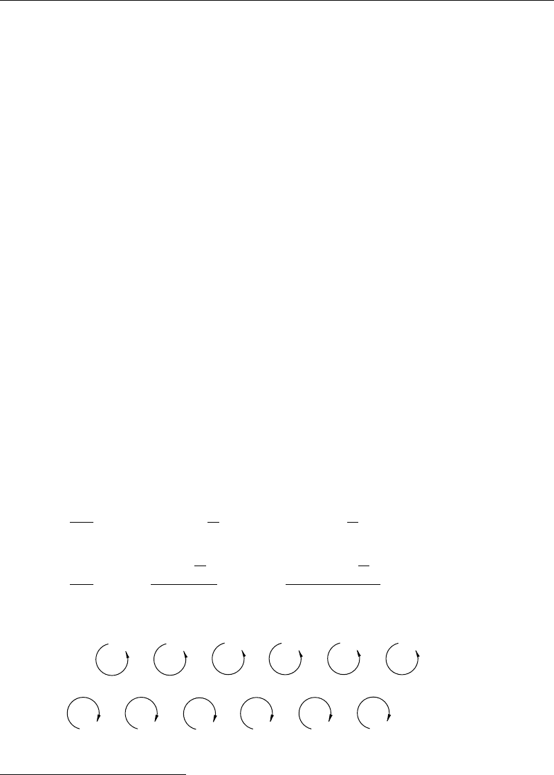
For flows past two-dimensional bodies, wake vortices are found to alternately shed from
the two sides of the body. Their pattern tends to be initially symmetrical (providing the
body is symmetrical) but soon changes to an alternating pattern, as seen in Figure 3.8.1.
Von Kármán questioned whether this alternating pattern (called a vortex street) was
necessarily the only pattern that could exist; in other words, was the pattern stable?
To idealize the problem, he omitted the body and considered two rows of vortices,
each consisting of vortices extending to infinity for both positive and negative x. The
upper row consists of counterclockwise vortices at x = na n = 1 2 y= b/2,
with circulation , and the lower row of clockwise vortices at x = n +ca n =
1 2 −1 <c<1y=−b/2 with circulation −. The complex velocity potential
for this flow (the calculations become unmanageable if we do not use complex variables
here) is then
w =
−i
2
n=−
ln
z −na −
ib
2
−ln
z −na −ca +
ib
2
=
−i
2
⎧
⎪
⎪
⎨
⎪
⎪
⎩
ln
⎡
⎢
⎢
⎣
sin
z −
ib
2
a
⎤
⎥
⎥
⎦
−ln
⎡
⎢
⎢
⎣
sin
z −ca +
ib
2
a
⎤
⎥
⎥
⎦
⎫
⎪
⎪
⎬
⎪
⎪
⎭
(3.8.1)
Figure 3.8.1 Kármán vortex street
1
Frederick William Lanchester (1868–1946) made many contributions to aerodynamics and automotive
engineering. His work was influential in the study of aircraft stability, and his 1919 book Aviation in Warfare:
The Dawn of the Fourth Arm eventually led to the development of the study of logistics and the field of
operations research.