Grace Robert. Advanced Blowout and Well Control
Подождите немного. Документ загружается.

6
Advanced
Blowout
and
Well Control
Figure
1.
I
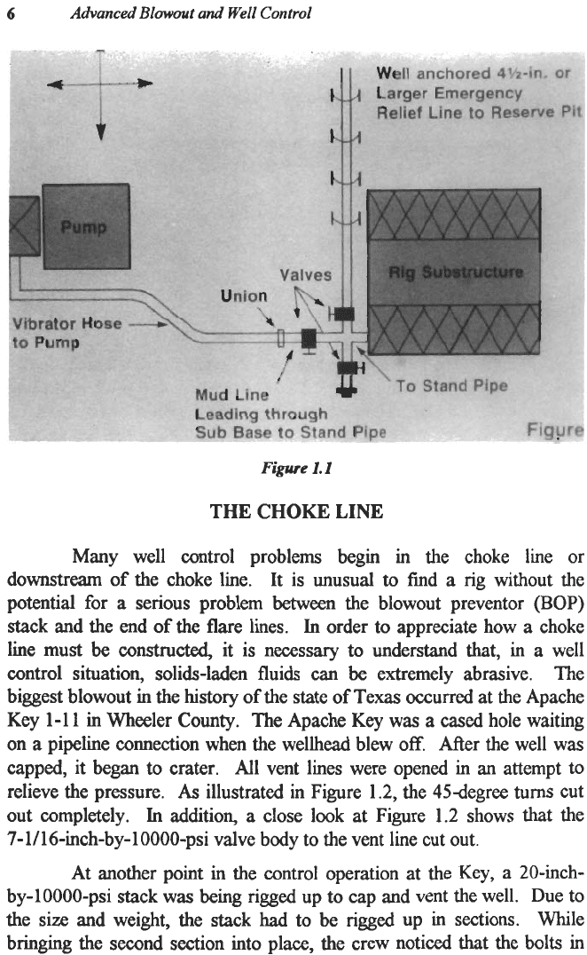
THE
CHOKE
LINE
Many well control problems begin in the choke line or
downstream of the choke line. It is unusual
to
find a rig without the
potential for
a
serious problem between the blowout preventor
(BOP)
stack and the end
of
the flare lines.
In
order to appreciate how a choke
line must
be
constructed,
it is necessary
to
understand that, in a well
control situation, solids-laden fluids can be extremely abrasive. The
biggest blowout in the
history
of the
state
of Texas occurred at the Apache
Key 1-1
1
in Wheeler Counly. The Apache Key was a cased hole waiting
on
a
pipeline connection when the wellhead blew
off.
After the well was
capped, it began to crater.
All
vent lines were opened in
an
attempt to
relieve the pressure.
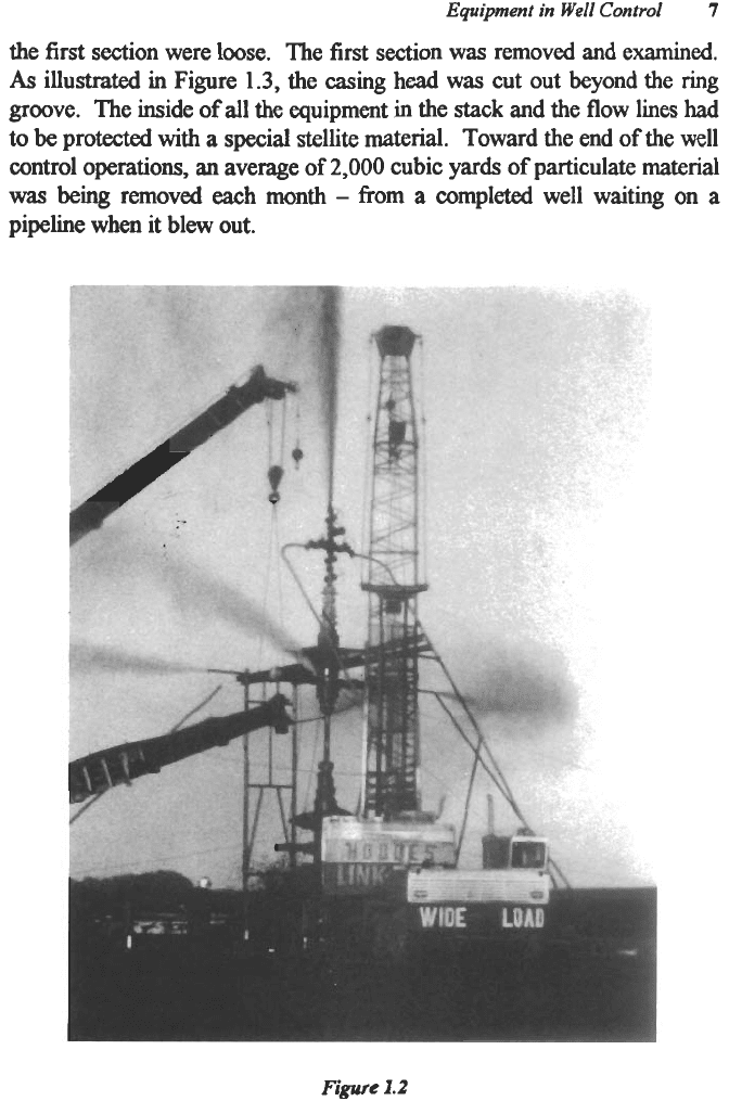
As
illustrated in Figure 1.2, the 45degree
turns
cut
out completely.
In
addition, a close look at Figure 1.2 shows
that
the
7-1/16-inch-by-1OOOO-psi
valve body to the vent line cut out.
At another point in the control operation at the
Key,
a 20-inch-
by-10000-psi stack was being rigged up
to
cap and vent the well. Due to
the size and weight, the stack
had
to be rigged up in sections. While
bringing the second section into place, the crew noticed that the bolts in
Equipent
in
Well
Control
7
the
first
section were loose.
The first section
was
removed and examined.
As
illustrated
in
Figure
1.3,
the casing
head
was
cut out beyond the ring
groove. The inside
of
all the equipment in the stack and the flow lines
had
to
be
protected
with
a special stellite
material.
Toward the end
of
the well
control
operations,
an average
of
2,000
cubic
yards
of
particulate material
was
being
removed
each
month
-
from
a
completed well waiting on a
pipeline when it blew out.
Figure
1.2

8
Advanced
Blowout
and
Well
Control
Figure
1.3
It is unusual for
dry
gas
to
erode. A production well blowout in
North
Afiica
was
producing approximately
200
mmscfpd. The
dry
gas
eroded through the
tree
just
as
the well was being killed. It had been
blowing out for approximately four weeks.
Production lines and
production chokes which were being used in the well control effort were
also severely eroded.
Add a small quantity
of
carbon dioxide and water and the results
can
be
catastrophic. At
a
large blowout in
East
Texas subjected
to
the
described conditions, the blowout preventer
was removed after the well
was killed. The body of the BOP was
almost
completely corroded and
eroded away.
Unfortunately, the industry
has
no guidelines for abrasion in the
choke line system. Erosion in production equipment is well defined by
API
Rp
14E.
Although production equipment is designed for extended
life and blowout systems are designed for extreme conditions over short
periods of time, the API
Rp
14E
offers insight into the problems and
variables associated with the erosion of equipment under blowout
conditions.
This
Recommended Practice relates
a
critical velocity to the
Equipment
in
Well
Control
9
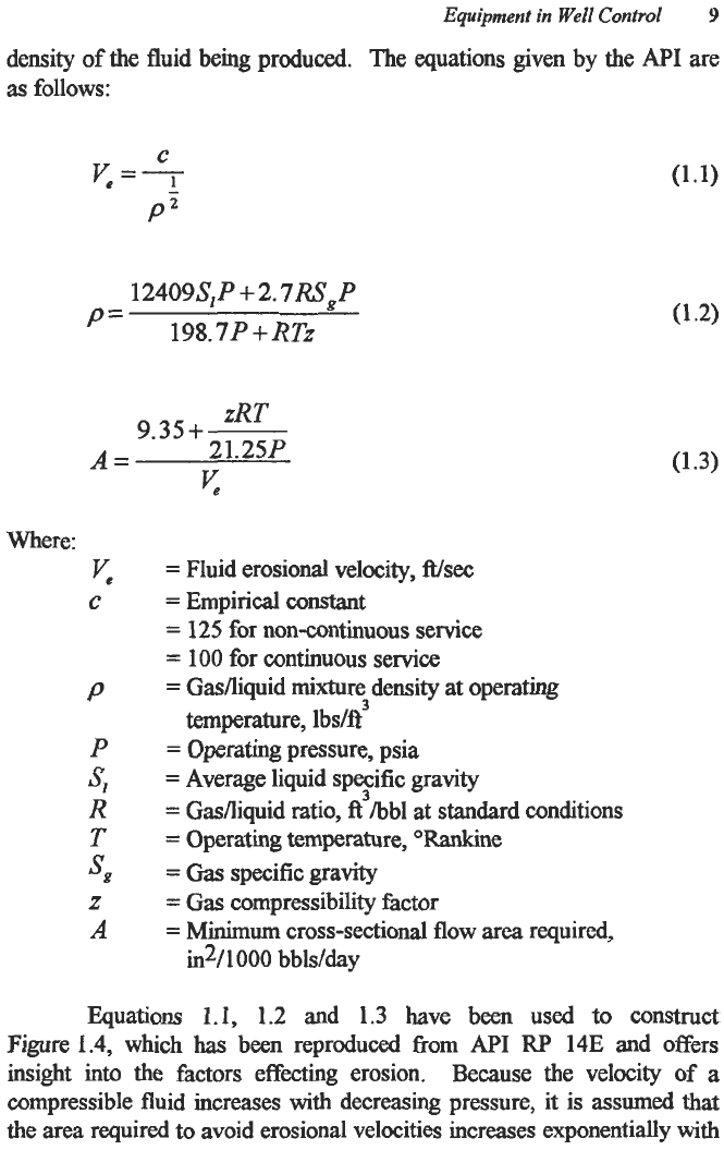
density of the fluid being produced. The equations given by the
API
are
as
follows:
124094
P
+
2.
7RSg
P
'=
198.7
P
+
RTz
zRT
21.25P
9.35+
A=
yc
(1.3)
Where:
y.
C
P
P
R
T
4
SB
Z
A
=
Fluid erosional velocity,
Wsec
=
Empirical constant
=
125
for non-continuous service
=
100 for continuous service
=
Gasfliquid mixture density
at
operating
=
Operating pressure, psia
=
Average liquid specific gravity
=
Gasfliquid ratio, fi3hbl at standard conditions
=
Operating temperature, "Rankine
=
Gas
specific gravity
=
Gas compressibility factor
=
Minimum
cross-sectional flow
area
required,
3
temperature, Ibs/ft
in%
000
bbls/day
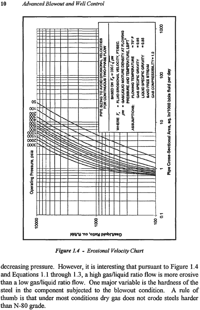
Equations
1.1,
1.2
and 1.3 have been used
to
construct
Figure
1.4,
which
has
been reproduced from
API
RP 14E and offers
insight
into
the factors effecting erosion,
Because the velocity
of
a
compressible fluid increases with decreasing pressure, it is assumed that
the area required to avoid erosional velocities increases exponentially with
10
Advanced
Blowout
and Well
Control
If
i
____~
Figure
1.4
-
Erosional
Velocity
Chart
decreasing pressure. However, it is interesting that pursuant to Figure
1.4
and Equations
1.1
through
1.3,
a
high
gasfliquid ratio
flow
is more erosive
than
a
low gasfliquid ratio
flow.
One major variable is the hardness
of
the
steel
in the component subjected to the blowout condition.
A
rule
of
thumb
is
that
under most conditions
dry
gas does not erode steels harder
than
N-80
grade.
Equipment
in
Well
Control
11
The presence of solids
causes
the
system
to become virtually
unpredictable. Oil-field service companies specializing in
fracture
stimulation
as
well
as
those involved
in
slurry pipelines are very familiar
with the erosional effects
of
solids in the presence of
only
liquids. Testing
of surface facilities indicates
that
discharge lines, manifolds and swivel
joints
containing
elbows
and short radius bends will remain intact for
up
to
six
months
at
a velocity
of
approximately
40
feet per second even
at
pressures up to
15000
psi. Further tests have
shown
that, in addition
to
velocity, abrasion is governed
by
the impingement angle or angle
of
impact of the slurry
solids
as
well
as
the strength and ductility
of
the pipe
and the hardness of the solids. At an impingement angle of
10
degrees
or
less, the erosion
wear
for
a hard, brittle material is essentially zero.
In
these tests, the maximum wear rate occurred when the impingement angle
was between
40
and
50
degrees. The wear rate increased when the solids
in
the slurry were harder
than
the tubular surfke. Sand is slightly harder
than
steel. Barite is much less abrasive
than
hematite.
@
Hydrdc
Gate
Vdve
@
Studded
Gar
to
Choke
Manifold
8
Choke
Lm
-
mninun
00
4
Inches
I
0
K1
@
Dr%
Spod
Mud
Gate
Vdve
:f
6
Figure
1.5
-
Choke
Line
There is no authority for the erosion and wear rate when
solid5
such
as
sand and barite are added to gas and drilling mud in a blowout or
a well control situation. There can
be
little doubt that the steels are
eroding under most circumstances.
API
RP
14E
merely states that the
12
empirical constant,
c
,
should be reduced if sand production is anticipated.
For well control situations, these
data
dictate that it is imperative
that
all
lines must
be
straight if
at
all
possible.
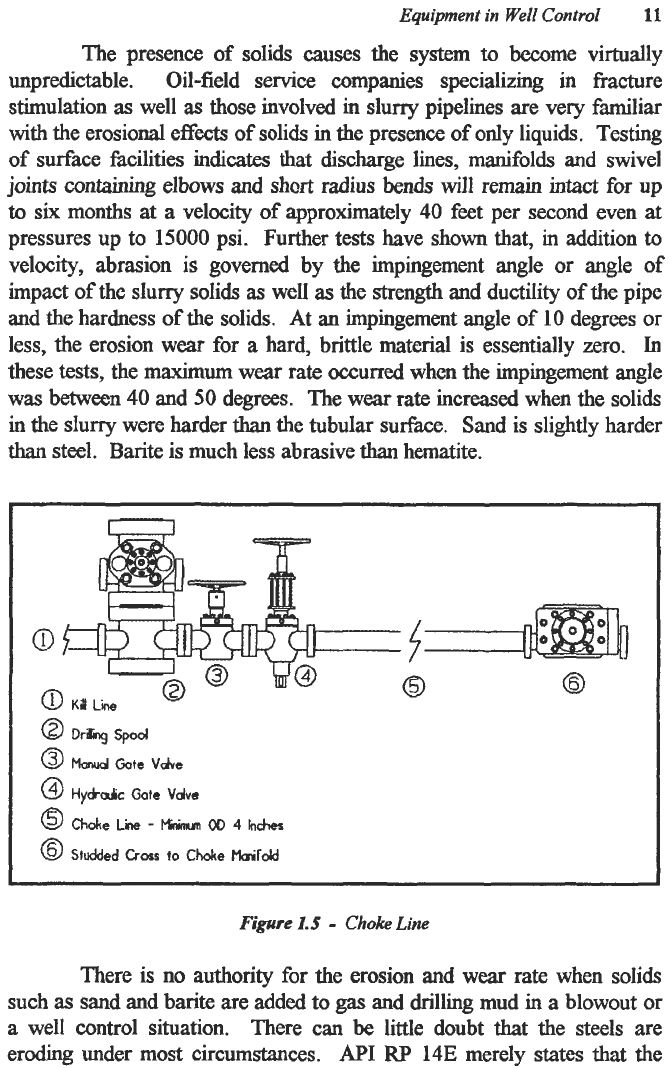
A typical choke line is shown in Figure
1.5.
As
illustrated, two
valves are flanged
to
the drilling spool. There are outlets on the body of
the blowout preventers. However, these outlets should not be used on a
routine basis since severe body wear and erosion may result. One valve is
hydraulically operated while the other is the backup or safety valve. The
position of the hydraulic valve is important.
Most
often it is outboard
with a safety valve next to the spool to be used only if the hydraulic valve
fails
to
operate properly. Many operators put the hydraulic valve inboard
of the safety valve. Experience
has
shown that the short interval between
the wellbore and the valve
can
become plugged with
drill
solids or barite
during the normal course of drilling. Therefore, when
a
problem does
occur, the manifold is inoperable due to plugging. The problem
has
been
minimized and often eliminated by placing the hydraulic valve next to the
casing spool. The outboard position for the hydraulic valve is the better
choice under
most
circumstances since the inboard valve is always the
safety valve. If the hydraulic valve is outboard, it is important that the
system be checked and flushed regularly
to
insure that
the
choke line
is
not
obstructed with drill solids.
In
areas where underbalanced drilling is routine, such
as
West
Texas, drilling with
gas
influx is normal and the wear on well control
equipment
can
be
a
serious problem.
In
these areas, it is not uncommon
to have more
than
one choke line to the manifold.
The
theory is sound.
A
backup choke line, in the event
that
the primary line washes out or is
plugged, is
an
excellent approach.
A
basic rule in well control is to have
redundant systems where a fiiilure in
a
single piece of equipment does not
mean disaster for the operation. However, the second choke line must be
as
substantial and reliable
as
the primary choke line. In one instance, the
secondary choke line
was
a
2-inch line from the braden head. The
primary choke line failed and the secondary line failed even faster. Since
the secondary line was on the braden head with no
BOP
below, the well
blew out under the substructure, caught fire and burned the rig.
Therefore, the secondary choke line should come from the kill-line side or
from
a
secondary drilling spool below an additional pipe
ram.
In addition,
it must meet the same specifications for dimension and pressure
as
the
primary choke line.
Advanced
Blowout
and
Well
Cmtrol
Equi-t
in
Well
Control
13
The choke lie fiom the valves to the choke manifold is
a
constant
problem.
This
line must be flanged, have
a
minimum
outside diameter
of
4
inches and should be STRAIGHT
between
the stack and the manifold.
Any bends, curves or angles are very likely
to
erode.
When
that happens,
well control becomes very difficult, lost, extremely hazardous or all
of
the
aforementicmed.
Just
remember,
STRAIGHT
and
no
threaded
connections.
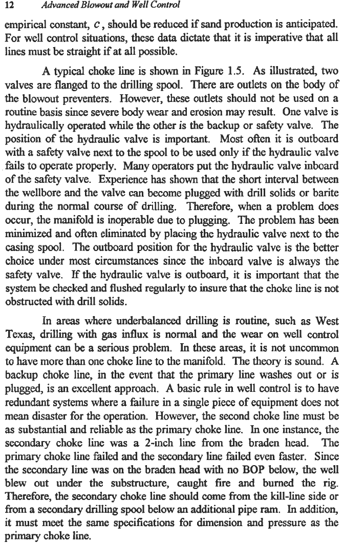
If
turns
in the choke line
are
required,
they should be made with
T’s and targets
as
illustrated
in
Figurc
1.6.
The
targets
must
be
filled
with
Babot and deep enough
to
withstand erosion. The direction
of
flow
must be into the target.
@b%spod
0
M
ate
Vhe
@
t-tydautc
Gcte
vdve
@
Choke
Lina
-
hnnum
OD
4
hchor
@
Studded
Cross
90
Choke
Maifold
@
Fknged
Torgeied
Turn
8
Tageted
Tee
Turn
lJ@
Figure
1.6
-
Choke
Line
with
Turns
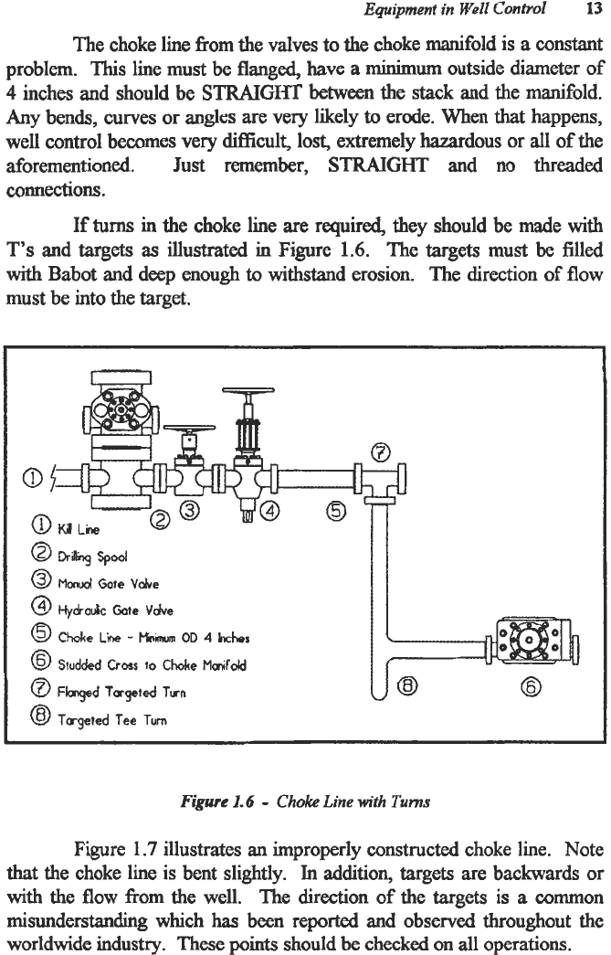
Figure
1.7
illustrates an improperly constructed choke line. Note
that
the choke line is bent slightly.
In
addition, targets
are
backwards or
with the flow
from
the well.
The
direction
of
the targets
is
a
mmmon
misunderstanding
which
has
been
reported
and
observed throughout the
worldwide
industry.
These
points
should be
checked
on
all
operations.
14
Advanced
Blowout
and
Well
Control
Continuous, straight
steel
lines are the preferred choke lines.
Swivel
joints
should
only
be
used in fracturing
and
cementing operations
and should not
be
used in
a
choke line
or
any
well
control
operation. At a
deep, high-pressure
sour
well in southern Mississippi,
a
hammer union
failed
and
the
rig
burned.
Figure
1.7
Finally,
the use
of
hoses
has
become more popular in recent
years.
Hoses are
quick
and
convenient
to
install.
However, hoses are
recommended
only
in
floating
drilling
operations
which offer no

Equipment
in
Well
Control
15
alternative. Further, consider
that,
in
the
two
most
serious well control
problems
in
the
North
Sea to date, hose failure
was
thc
root cause.
To
Separator
-
Ball Valve
Hydroulic
Choke
To
Separator
To
Flare
To
Flare
Figure
1.8
-
The Choke
Mangold
Hoses and swivel joints
work
well on
many
wells because serious
well control problems do not occur on many wells. However, when
serious well control problems do occur, solid equipment has better
integrity. Swivel
joints
can be used
on
the pumping side in kill operations
for short periods
of
time.
As
of
this writing, hose use should be restricted
to the suction side
of
the pumping equipment. Presently, hoses cannot be
recommended to replace choke lines. Although the literature is
compelling,
it
is illogical
to
conclude that rubber is harder than steel.