Grace Robert. Advanced Blowout and Well Control
Подождите немного. Документ загружается.


46
Advanced
Blowout
and Well
Control
Step
5
Once
the influx
has
been displaced, record the casing pressure
and compare
with
the
ori@
shut-in drillpipe pressure recorded
in
Step
1. It is important to note
that,
if the influx
has
been
completely displaced, the casing pressure should be equal
to
the
original shut-in drillpipe pressure.
Step
6
If the casing pressure is equal
to
the original shut-in drillpipe
pressure recorded in Step 1, shut in the well
by
keeping the casing
pressure constant while
slowing
the pumps. If the casing pressure
is greater
than
the original shut-in drillpipe pressure, continue
circulating for
an
additional circulation, keeping the drillpipe
pressure constant and then shut in the well, keeping the casing
pressure constant while
slowing
the pumps.
Step
7
Read,
record, and compare the shut-in drillpipe and casing
pressures. If the well
has
been
properly displaced, the shut-in
drillpipe pressure should
be
equal to the shut-in casing pressure.
Step
8
If the shut-in casing pressure is greater than the shut-in drillpipe
pressure, repeat
Steps
2
through
7.
step
9
If the shut-in drillpipe pressure is equal
to
the shut-in casing
pressure, determine the density of the kill-weight mud,
pl,
using
Equation
2.9
(Note that
no
“safety
factor“
is
recommended or
included):
Where:
h
=
Density
of
the
kill-weight mud,
ppg
Classic
Pressure
Control
Procedures
41
Pnl
Gp
D
=
Well depth, feet
=
Gradient of the original mud, psi/ft
=
Shut-in drillpipe pressure, psi
Step
10
Raise the mud weight in the suction pit
to
the density determined
in
step
9.
Step
11
Determine the number of strokes
to
the bit by dividing the
capacity of the drill string in barrels by the capacity of the pump
in
barrels per stroke according to Equation 2.10:
Where:
STB
CdP
'dP
'hw
'dc
'hw
'dc
CP
cdp'dp
+
chwzhw
+
'&'&
STB
=
CP
=
Strokes to the bit, strokes
=
Capacity of the drillpipe, bbVft
=
Capacity
of
the heavy-weight drillpipe, bbVft
=
Capacity of the drill collars, bbVft
=
Length of the drillpipe, feet
=
Length
of
the heavy-weight drillpipe,
feet
=
Length
of
the drill collars, feet
=
Pump capacity, bbVstroke
(2.10)
step 12
Bring the pump to
speed,
keeping the casing pressure constant.
Step
13
Displace the kill-weight mud to the bit, keeping the casing
pressure constant.
Warning! Once the pump rate
has
been established, no further
adjustments
to
the choke should
be
required. The casing pressure
48
Advanced
Blowout
and
Well Contml
should
remain
constant
at
the
initial
shut-in drillpipe pressure. If
the casing pressure begins to rise, the procedure should be
terminated
and the well shut in.
Step
14
After pumping the number
of
strokes required for the kill mud
to
reach the bit, read and record the drillpipe pressure.
Step
15
Displace the kill-weight mud to the surface, keeping the drillpipe
pressure constant.
Step
16
With kill-weight mud
to
the
surface,
shut in the well by keeping
the casing pressure constant while slowing the pumps.
Step
17
Read and record the shut-in drillpipe pressure and the shut-in
casing pressure. Both pressures should be
0.
Step
18
Open the well
and
check for flow.
step
19
If the well is flowing, repeat the procedure.
Step
20
If no flow is observed, raise the mud weight to include the desired
trip margin and circulate until the desired mud weight
is
attained
throughout the system.
The discussion of each
step
in detail follows:
Classic
Pressure
Control
Procedures
49
step
1
On
each tour,
read
and record the standpipe pressure at several
flow rates in strokes per minute (spm), including the anticipated
kill rate for each pump.
Experience
has
shown
that
one of the most difficult aspects
of
any
kill procedure is bringing the pump
to
speed without permitting an
additional
influx
or fracturing the casing shoe.
This
problem is
compounded by attempts
to
achieve a precise kill rate. There
is
nothing magic about the kill rate
used
to circulate out a kick.
In
the early days of pressure control, surface facilities were
inadequate to bring an
influx
to
the surface at a
high
pump speed.
Therefore, one-half normal speed became the arbitrary rate of
choice for circulating the
influx
to the surface. However, if only
one rate such
as
the one-half speed is acceptable, problems can
arise when the pump
speed
is slightly less or slightly more than
the precise one-half
speed.
The reason for the potential problem
is
that the circulating pressure at rates other than the kill rate is
unknown.
Refer
to
firther discussion after Step
4.
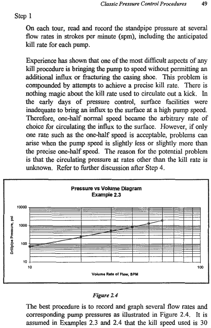
Pressure
vs
Volume Diagram
Example
2.3
100
10
10
100
Vdume
Rate
of
Flow.
SPM
Figure
2.4
The best procedure is to record and graph several
flow
rates and
corresponding pump pressures
as
illustrated
in Figure
2.4.
It is
assumed in Examples
2.3
and
2.4
that the kill speed used is
30
50
Advanced Blowout
and
Well
Control
strokes per minute. However, the
actual
pump speed used need
not be exactly
30
strokes per minute. The drillpipe pressure
correspondmg to the
actual
pump speed being used could be
verified readily using Figure
2.4.
step
2
After a kick
has
been taken and prior to pumping, read and record
the drillpipe and casing pressures. Determine the pump pressure
at the kill speed.
Important! If in doubt at any time during the entire procedure,
shut in the well, read and record the shut-in drillpipe pressure and
the shut-in casing pressure and proceed accordingly.
It is not uncommon for the surface pressures to fluctuate slightly
due to temperature, gas migration, or gauge problems. Therefore,
for hture reference it is important to record the surface pressures
immediately prior
to
commencing pumping operations.
The second statement is extremely important to keep in mind.
When
in doubt, shut in the well! It
seems
that the prevailing
impulse is to continue circulating regardess of the consequences.
If the condition of the well
has
deteriorated
since
it was shut in, it
deteriorated during the pumping
phase.
When
in
doubt, shut
in
the well, read the surface pressures, compare with the original
pressures and evaluate the situation prior to hrther operations. If
something is
wrong
with the displacement procedure being used,
the situation
is
less likely
to
deteriorate while shut in and more
likely to continue
to
deteriorate if pumping is continued. The well
was under control when initially shut in.
Step
3
Bring the pump to
a
kill
speed,
keeping the casing pressure
constant.
This
step
should require less
than
five minutes.
As
previously
stated,
bringing the pump to speed is one of the
most difficult problems in any well control procedure. Experience
has
shown that the most practical approach is to keep the casing

Classic Pressure
Control
Procedures
51
pressure constant at the shut-in casing pressure while bringing the
pump to
speed.
The initial gas expansion is negligible over the
allotted time of five minutes required
to
bring the pump to speed.
It is not important that the initial volume rate
of
flow be exact.
Any
rate
within
10%
of
the kill rate is satisfactory.
This
procedure will establish the
correct
drillpipe pressure
to
be used
to
displace the kick. Figure
2.4
can
be
used
to
verie the drillpipe
pressure being used.
Practically, the rate can be lowered or raised at any time during
the displacement procedure. Simply
read
and record the
circulating casing pressure and hold that casing pressure constant
while adjusting the pumping rate
and
establishing
a
new drillpipe
pressure. No more than one to
two
minutes can be allowed for
changing the rate when the gas
influx
is near the surEace because
the expansion near the surfice is quite rapid.
Step
4
Once the pump is
at
a satisfactory
kill
speed,
read and record the
drillpipe pressure. Displace the influx, keeping the recorded
drillpipe pressure constant.
Actually, all
steps
must be considered together
and
are integral
to
each other. The
correct
drillpipe pressure used
to
circulate out
the influx will
be
that
drillpipe pressure established by Step
4.
The pump rates and pressures established in Step
1
are to be used
as
a
confirming reference only once the operation
has
commenced.
Consideration
of
the U-Tube Model in Figure
2.3
clearly
illustrates
that,
by holding the casing pressure constant at the
shut-in casing pressure while bringing the pump to speed, the
appropriate drillpipe pressure will be established for the selected
rate.
All adjustments
to
the circulating operation must
be
performed
considering the casing annulus pressure. In adjusting the pressure
on
the circulating system, the drillpipe pressure response must be
considered secondarily because there
is
a significant lag time
between any choke operation
and
the response on the drillpipe

52
Advanced
Blowout
and Well
Control
pressure gauge,
This
lag time
is
caused by the time required
for
the pressure transient
to
travel
from
the
choke to the drillpipe
pressure gauge. Pressure responses travel at the speed of sound
in the medium. The
speed
of sound is 1,088 feet per second in
air
and
about
4,800
feet
per
second
in
most
water-based drilling
muds. Therefore, in
a
10,000-foot well,
a
pressure transient
caused
by
opening
or closing the choke would not be reflected on
the standpipe pressure
gauge
until four seconds later. Utilizing
only the drillpipe pressure
and
the
choke usually results in large
cyclical variations which cause additional influxes
or
unacceptable pressures
at
the
casing
shoe.
Once
the influx
has
been
displaced, record the casing pressure
and compare with the
original
shut-in drillpipe pressure recorded
in Step
1.
It
is
important
to
note
that,
if the
influx
has been
completely displaced, the casing pressure should be equal
to
the
original
shut-in drillpipe pressure.
Consider the
U-Tube
Model presented in Figure
2.5
and compare
with the U-Tube Model illustrated in Figure
2.3.
If the influx
has
been
properly and completely displaced,
the
conditions
in
the
annulus side
of
Figure
2.5
are exactly the same
as
the conditions
in the drillpipe side of Figure
2.3.
If
the frictional pressure losses
in the annulus are negligible, the conditions in the annulus side of
Figure
2.5
will
be
approximately the same
as
the drillpipe side
of
Figure
2.3.
Therdore, once the
influx
is displaced, the circulating
annulus pressure should be equal to the initial shut-in drillpipe
pressure.
Step
6
If
the casing pressure
is
equal
to the original shut-in drillpipe
pressure recorded in Step 1, shut in the well by keeping the casing
pressure constant while
slowing
the pumps.
If
the casing pressure
is
greater
than the
original
shut-in drillpipe pressure, continue
circulating for
an
additional circulation, keeping the drillpipe
pressure constant and then shut in the well, keeping the casing
pressure
constant
while
slowing
the pumps.
Classic
Pressure
Control Procedures
53
BILLPIPE
P,D
ANNULUS
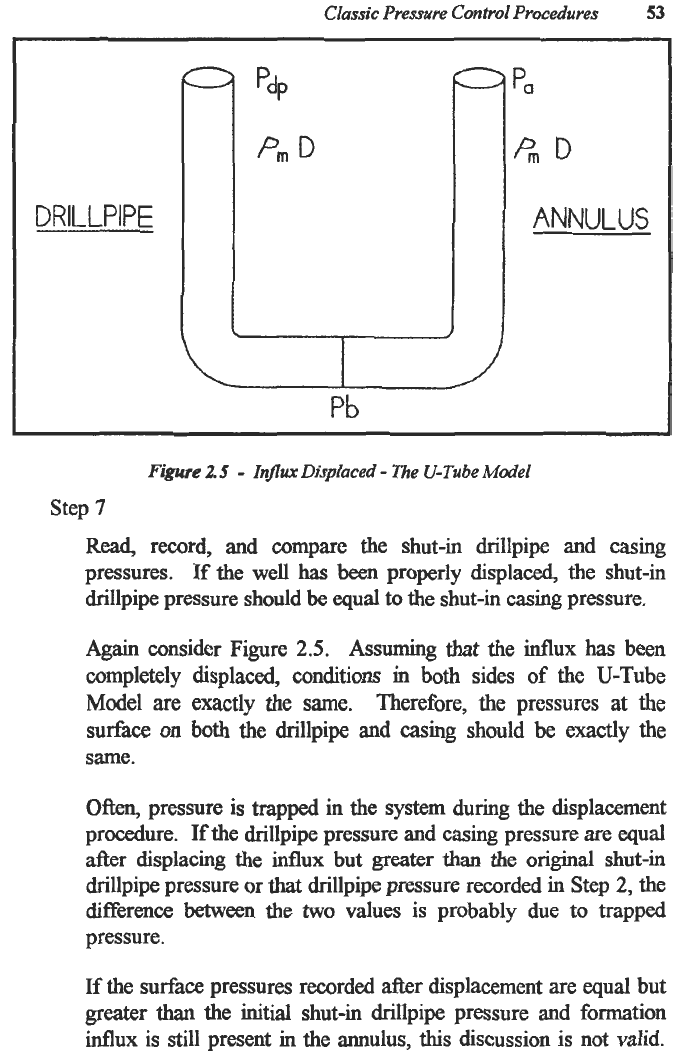
Figure
2.5
-
Influx Displaced
-
The U-Tube Model
Step
7
Read,
record,
and
compare the shut-in drillpipe and casing
pressures. If the well
has
been
properly displaced, the shut-in
drillpipe pressure should
be
equal to the shut-in casing pressure.
Again
consider Figure
2.5.
Assuming that the
influx
has been
completely displaced, conditions in
both
sides
of
the U-Tube
Model are exactly the same. Therefore, the pressures at the
surface
on
both the drillpipe and casing should
be
exactly the
same.
Often, pressure
is
trapped in the system during the displacement
procedure. If the drillpipe pressure and casing pressure are
equal
after displacing the influx but
greater
than the original shut-in
drillpipe pressure or
that
drillpipe pressure recorded in Step
2,
the
difference
Ween
the
two
values
is
probably due to trapped
pressure.
If
the surface pressures recorded
after
displacement are
equal
but
greater
than
the initial shut-in drillpipe pressure and formation
influx is still present in the annulus,
this
discussion
is
not valid.
54
Advanced
Blowout
and
Well
Control
These conditions are discussed in the special problems in
Chapter
4.
Step
8
If
the shut-in casing pressure is greater
than
the shut-in drillpipe
pressure, repeat
Steps
2
through
7.
If,
after
displacing the initial
influx,
the shut-in casing pressure is
greater
than
the shut-in drillpipe pressure, it is probable
that
an
additional
influx
was
permitted
at
some point during the
displacement procedure.
Therefore, it
will
be necessary to
displace
that
second
influx.
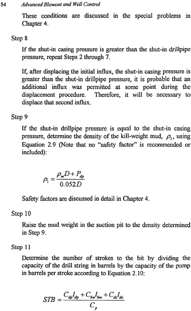
Step
9
If
the shut-in drillpipe pressure is
equal
to
the shut-in casing
pressure, determine the density
of
the kill-weight mud,
pi,
using
Equation
2.9
(Note that no “safety factor”
is
recommended or
included):
pm
+
‘dp
”
=
0.0520
Safety
factors are discussed
in
detail in Chapter
4.
Step
10
Raise the mud weight in the suction pit
to
the density determined
in
step
9.
step
11
Determine the number
of
strokes
to
the bit by dividing the
capacity of the
drill
string in barrels by the capacity
of
the pump
in barrels per stroke according
to
Equation
2.10:

Classic
Pressure
Control
Procedures
55
Sections or different weights of drillpipe, drill collars or heavy
weight drillpipe may
be
added or deleted
from
Equation
2.10
simply by adding
to
or subtracting from the numerator of
Equation
2.10
the product of the capacity and the length of the
section.
Step
12
Bring the pump
to
speed,
keeping the casing pressure constant.
Step
13
Displace the kill-weight mud
to
the bit, keeping the casing
pressure constant.
Warning! Once the pump rate
has
been established, no further
adjustments
to
the choke should
be
required. The casing pressure
should remain constant
at
the initial shut-in drillpipe pressure. If
the casing pressure
begins
to rise, the procedure should be
terminated and the well shut in.
It
is
vital
to understand Step
13.
Again, consider the U-Tube
Model in Figure
2.5.
While the kill-weight mud is being
displaced to the bit
on
the
drillpipe side, under dynamic conditions
no changes are occurring in any
of
the conditions on the annulus
side. Therefore, once the pump rate
has
been established, the
casing pressure should not change and it should not be necessary
to
adjust
the choke
to
maintain the constant drillpipe pressure. If
the casing pressure does begin to increase, with everythug else
being constant, in all probability there is some gas in the annulus.
If there
is
gas in the annulus,
this
procedure must be terminated.
Since the density
of
the mud at the surface has been increased to
the kill, the proper procedure under these conditions would be the
Wait and Weight
Method.
Therefore, the Wait and Weight
Method would
be
used
to
circulate the
gas
in the annulus to the
surface and control the well.
Step
14
After pumping the number of strokes required for the kill mud to
reach the bit, read and record the drillpipe pressure.