Glusker J.P., Trueblood K.N. Crystal Structure Analysis: A Primer
Подождите немного. Документ загружается.

148 The derivation of trial structures. II. Patterson, heavy-atom, and isomorphous replacement methods
Multiple Bragg reflection
A very different but important approach to phase measurement
involves “double reflection.” This is a physical effect that occurs when
the crystal is oriented so that two reciprocal lattice points, h
1
, k
1
, l
1
and h
2
, k
2
, l
2
, lie simultaneously in the diffracting position; that is,
both lie on the surface of the sphere of reflection (the Ewald sphere)
at the same instant. The result is two beams that are diffracted in the
direction normally expected for h
1
, k
1
, l
1
, and which interfere with each
other. One is the normally expected h
1
k
1
l
1
Bragg reflection (the primary
beam), and the other, also in the h
1
k
1
l
1
direction, results from the h
2
k
2
l
2
Bragg reflection (the secondary beam) acting as the incident beam for
the h
1
− h
2
, k
1
− k
2
, l
1
−l
2
Bragg reflection (the coupling beam). The
amplitude of the resultant Bragg reflection gives information on the
phase difference of these two waves. This effect is variously described
as the Renninger effect (Renninger, 1937), the Umweganregung effect (if
I(h
1
k
1
l
1
) is increased at the expense of I (h
2
k
2
l
2
)), or the Aufhellung effect
(if I (h
1
k
1
l
1
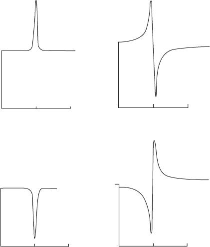
) is decreased). When a ¯-scan of the peak (through a very
small angle) is done it is found that there is an asymmetry, shown in
Figure 9.11, that depends on the value of the phase invariant. Therefore
a direct reading of ·
sum
is obtained:
·
sum
= ·(−h
1
, −k
1
, −l
1
)+·(h
2
, k
2
, l
2
)+·(h
1
− h
2
, k
1
− k
2
, l
1
−l
2
) (9.4)
primary beam secondary beam coupling beam
–0.05 –0.00 +0.05
–0.05 –0.00 +0.05
–0.05 –0.00 +0.05
–0.05
–0.00
+0.05
a
sum = −90⬚
a
sum = +90⬚
a
sum = 180⬚
a
sum = 0⬚
I
I
I
I
Y scan
Y scan Y scan
Y scan
(a)
(c)
(d)
(b)
Fig. 9.11 Multiple Bragg reflections.
Some idealized ¯-scans and values of
·
sum
(hkl) derived from peak profiles. If the
crystal is noncentrosymmetric, intermedi-
ate phase sum values will be found.

Summary 149
This is like a triplet phase relationship but is an equality rather than
a probability. A highly precise (six-circle) diffractometer is needed for
this experiment but, when available, such an instrument has provided
experimental data that have been used with good success (Hümmer
and Billy, 1986; Shen, 1998). Thus an experimental way of measuring
origin-independent structure invariants is provided.
Summary
The Patterson map
The map computed with amplitudes |F (hkl)|
2
, but no phase informa-
tion, will give a vectorial representation of the atomic contents of the
unit cell. The Patterson function, P(uvw), is expressed in the coordinate
system u, v, w in a cell of the same size and shape as that of the crystal.
It is calculated by
P(uvw)=
1
V
all h,k,l
F (hkl)
2
cos 2π(hu + kv + lw)
The peaks in this map occur at points whose distances from the origin
correspond in magnitude and direction with distances between atoms
in the crystal, because
P(uvw)=V
Ò(x, y, z) Ò(x + u, y + v, z + w)
dx dy dz
Ideally this map can be interpreted in terms of an atomic arrangement.
In practice, however, this is only possible if there are comparatively
few atoms in the structure or if some are very heavy. The map may
also be “sharpened” and the high origin peak removes if values of
{|E(hkl)
2
|−1} rather than |F (hk l)|
2
are used. A rotation of a Patterson
map can be used to identify the angle between two identical molecules
when noncrystallographic symmetry is present.
The heavy-atom method
If one or a few atoms of high atomic number are present, they will
dominate the scattering. These atoms can generally be located from a
Patterson map and the phases of the entire structure approximated by
the phases of the heavy atom(s). In the resulting electron-density map,
portions or all of the remainder of the structure will usually be revealed,
leading to improved phases and successively better approximations to
the structure.
Isomorphous replacement method
For very large structures, such as those of proteins, the isomorphous
replacement method is a good method for the experimental determi-
nation of phase angles. Two crystals are isomorphous if their space
150 The derivation of trial structures. II. Patterson, heavy-atom, and isomorphous replacement methods
groups are the same and their unit cells and atomic arrangements are
essentially identical. Since protein crystals contain solvent channels,
if heavy atoms (in solution) are soaked into them and the resulting
crystals are isomorphous with the unsubstituted (“native”) crystal, a
comparison of the two diffraction patterns will give relative-phase
information. If the positions of these added or replaced atoms can be
found from Patterson maps, their contributions to the phase angle of
each Bragg reflection can be calculated, and if the atoms are sufficiently
heavy, differences in intensities for the two isomorphs can be used to
determine the approximate phase angle for each Bragg reflection. At
least two heavy-atom derivatives are necessary for noncentrosymmetric
structures.
Multiple Bragg reflection
If the crystal is oriented so that two reciprocal lattice points lie simulta-
neously in the diffracting position, that is, both lie on the surface of the
sphere of reflection at the same instant, the resulting diffracted beam
contains information on a structure invariant involving three Bragg
reflections—the primary beam, the secondary beam, and the coupling
beam. This method requires specialized equipment.

Anomalous scattering
and absolute
configuration
10
The concept of the carbon atom with four bonds extending in a
tetrahedral fashion was put forward by van’t Hoff and Le Bel in
1874. It coincided with the realization that such an arrangement could
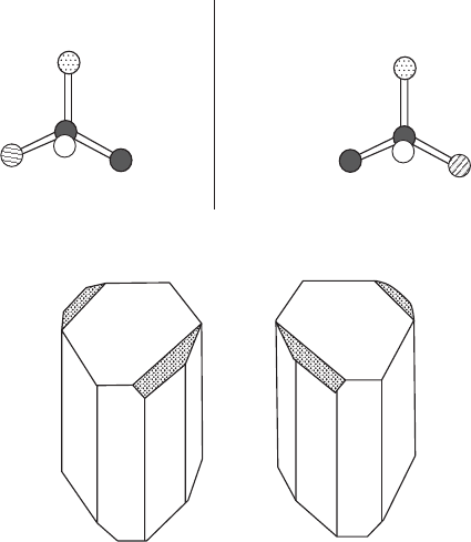
be asymmetric if the four substituents were different, as shown in
Figure 10.1a (van’t Hoff, 1874; Le Bel, 1874). Thus, for any compound
containing one such asymmetric carbon atom, there are two isomers of
opposite chirality (individually called enantiomers), for which three-
dimensional representations of their structural formulas are related
by a mirror plane. Aqueous solutions of these enantiomers rotate
the plane of polarized light in opposite directions. As discussed in
Chapter 7, Pasteur showed that crystals of sodium ammonium tartrate
had small asymmetrically located faces and that crystals with these
so-called “hemihedral faces” rotated the plane of polarization of light
clockwise, while crystals with similar faces in mirror-image positions
rotated this plane of polarization counterclockwise. Thus the external
form (that is, the morphology) of the crystals illustrated in Figure 10.1b
was used to separate enantiomers (see Patterson and Buchanan, 1945).
Pure enantiomers can only crystallize in noncentrosymmetric space
groups unless both isomers are present.
But even if the chemical formula and the three-dimensional structure
of a molecule such as tartaric acid have been determined by standard
X-ray diffraction methods, there is an ambiguity about the absolute
configuration. Information about the absolute configuration is not con-
tained in the diffraction pattern of the crystal as it is normally measured.
Thus, although the substituents on the asymmetric carbon atoms have
been identified, and even the detailed three-dimensional geometry of
the molecule has been determined, it is not known which of the two
enantiomers (mirror-image forms, analogous to those shown in Fig-
ure 10.1a) represents the three-dimensional structure of a particular
individual molecule that has some distinguishing chiral property, such
as the ability to rotate the plane of polarized light to the right. In other
words, what is the absolute structure of the dextrorotatory form of the
compound under study?
151
152 Anomalous scattering and absolute configuration
A
(a)
(b)
B
Mirror
C
D
A
D
C
B
Dextrorotatory sodium
ammonium tartrate
Levorotatory sodium
ammonium tartrate
Fig. 10.1 Absolute configurations.
(a) The asymmetric carbon atom. If A, B, C, and D attached to the tetrahedral carbon
atom are all different, there are two chiral isomers related to each other by a mirror
plane. In a similar way, the entire structure of a crystal may be chiral.
(b) Hemihedral faces (shaded) on sodium ammonium tartrate crystals (used by Pas-
teur to differentiate dextrorotatory from levorotatory forms).
A means of determining the absolute configurations of molecules
was, however, provided by X-ray crystallographic studies. It was made
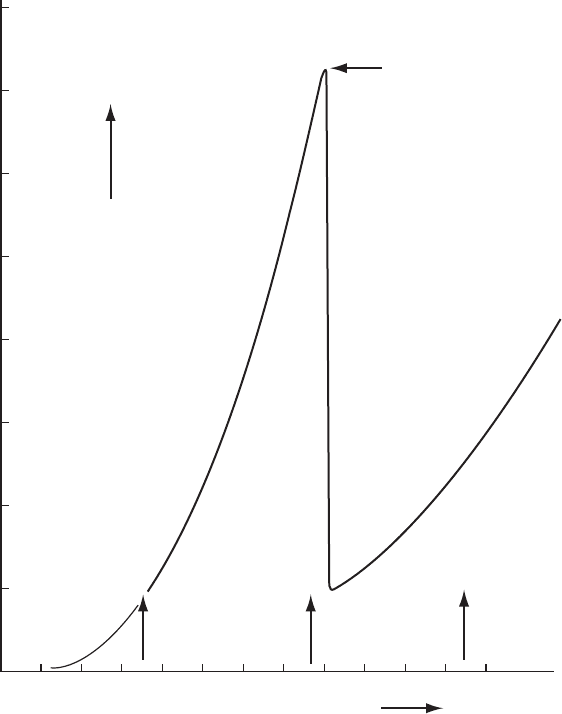
possible by the observation that the absorption coefficient of an atom
for X-rays shows discontinuities when plotted as a function of the
wavelength of the incident X-radiation. These discontinuities, shown
in Figure 10.2, are graphically described as “absorption edges.” At
wavelengths at the absorption edge of an atom, the energy (inversely
proportional to wavelength) of the incident X rays is sufficient either to
excite an electron in the strongly absorbing atom to a higher quantum
state or to eject the electron completely from the atom. This has an effect
on the phase change of the X rays on scattering. The scattering factor for
the atom becomes “complex,” and the factor f is replaced by
f = f
i
+ f
i
+if
i
(10.1)
where f
and f
vary with the wavelength of the incident radiation.
While f
causes no change in phase (it remains at 180
◦
), f
causes a
phase change of 90
◦
, which is the reason that the Friedel-pair symmetry
breaks down. The value of f
is largest when the wavelength is near
Anomalous scattering and absolute configuration 153
Wavelength of radiation (Å)
Mo Ka
C
r KaCu Ka
Mass absorption
coefficient m/r (cm
2
/g)
K absorption edge
for Co (1.608 Å)
400
350
300
250
200
150
100
50
0 0.2 0.4 0.6 0.8 1.0 1.2 1.4 1.6 1.8 2.0 2.2 2.4 2.6
Fig. 10.2 Absorption of X rays of various wavelengths by a cobalt atom.
The mass absorption coefficient for cobalt as a function of wavelength. Note the discon-
tinuity near the absorption edge (1.608 Å); beyond it, there is a gradual increase in the
coefficient as the wavelength of the radiation increases.
the absorption edge (as for cobalt in a structure studied with copper Kα
radiation; see Figure 10.2).
When visible light passes through transparent matter, such as a glass
prism or a colorless crystal, its speed is decreased from the value it had
in a vacuum. This decreased speed depends on the wavelength of the
light. The refractive index of a material is the ratio of the velocity of
light in vacuo to its velocity when it passes through this medium. Since
white light consists of rays with a variety of wavelengths (from red
to violet), rays with different wavelengths will be refracted at slightly
different angles when they enter a material at an angle. This separation
of light so that the individual colors of the component waves become
visible is called “dispersion.” The violet and blue rays (of shorter wave-
lengths) are slowed more and therefore are bent to a greater extent
154 Anomalous scattering and absolute configuration
than are the red and orange rays, with longer wavelengths; rays with
shorter wavelengths have a larger refractive index. The result of such
dispersion is a beautiful rainbow-like display of colors, such as that seen
when sunlight passes through and exits a glass prism. This dispersion
becomes “anomalous” when an energy absorption band is encountered
and a discontinuity occurs; the dispersion is normal on either side of the
absorption band, but at the absorption edge the refractive index is larger
for longer wavelengths, rather than shorter as is normal. In this area
near an absorption edge this plot of wavelength versus refractive index
shows an increase of refractive index with wavelength (so that blue
light is less refracted than red), the opposite of normal expectation. This
is called “anomalous dispersion” or “anomalous scattering,” meaning
that one is studying the area of a spectrum near an absorption edge.
All atoms scatter anomalously to some extent, but at wavelengths
near the absorption edge of a scattering atom, anomalous scattering
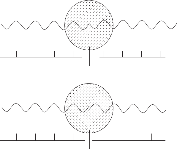
will be especially noticeable. If an atom in the structure absorbs, at least
moderately, the X rays being used, then this absorption will result in a
phase change for the X rays scattered by that atom, relative to the phase of the X
rays scattered by the other atoms of the structure, the equivalent of advanc-
ing or delaying the radiation for a short time as shown in Figure 10.3
[that is, equivalent to a hesitation (“gulp”) at the time of scattering].
Normal scattering
Anomalous scattering
Atom
Atom
Diffracted beam
Diffracted beam
Direct beam
Direct beam
(a)
(b)
Fig. 10.3 Phase change on anomalous scattering.
(a) Normal scattering with a phase change of 180
◦
. (b) Anomalous scattering with a different phase change.
Anomalous scattering and absolute configuration 155
This implies that in order to demonstrate anomalous scattering, the
crystal must contain at least two different types of atoms. The phase
change caused by f
changes the path length of the scattered radiation,
as illustrated schematically in Figure 10.3, and the result is an effect on
the intensities of the diffracted beams. When there is none of this so-
called “anomalous scattering,” the intensities of the Bragg reflections
with indices h, k, l and
¯
h,
¯
k,
¯
l are the same (Friedel’s Law). When there is
anomalous scattering, the intensities of these two Bragg reflections may
be different because of changes in effective path differences between
scattered waves arising from the phase change on absorption by the
anomalously scattering atom.
The difference in intensities may alternatively be thought of as a
result of the complex nature of the scattering factor, f
i
[see Eqn.
(10.1)], so that the absolute value of F (hkl) is different from that of
F (−h, −k, −l), as illustrated in Figure 10.4. We showed in Eqn. (10.1)
that if there is an anomalous scatterer in the crystal, f is replaced by
f + f
+if
.LetA
= G( f + f
)+A and B
= H( f + f
)+B, where A
and B refer to the rest of the structure and G and H to the anomalous
scatterer. Remember that f and f
scatter with a phase change of 180
◦
,
while f
scatters with a phase change of 90
◦
. As a result, since
F (hkl)=(A
+iGf
)+i(B
+iHf
)=(A
− Hf
)+i(B
+ Gf
) (10.2)
|F (hkl)|
2
=(A
− Hf
)
2
+(B
+ Gf
)
2
(10.3)
and similarly
F (
¯
h
¯
k
¯
l)=(A
+iGf
) − i(B
+iHf
)=(A
+ Hf
) − i(B
− Gf
) (10.4)
|F (
¯
h
¯
k
¯
l)|
2
=(A
+ Hf
)
2
+(B
− Gf
)
2
(10.5)
it then follows that
|F (hkl)|
2
−|F (
¯
h
¯
k
¯
l)|
2
=4f
(B
G − A
H) (10.6)
Thus, when the incident X-radiation is of a wavelength near that of the
absorption edge of an atom in a noncentrasymmetric structure, |F (hkl)|
does not equal |F(
¯
h
¯
k
¯
l)|. Under normal conditions the wavelength of the
X-radiation used for a diffraction experiment is far from any absorp-
tion edge and these two quantities, |F (hkl)| and |F (
¯
h
¯
k
¯
l)|, are equal. If
anomalous scattering occurs, the magnitude of the difference between
|F (hkl)|
2
and |F (
¯
h
¯
k
¯
l)|
2
for the two Bragg reflections (called “Friedel
pairs” or “Bijvoet pairs”) is a function of f
(which depends on how
near the incident radiation is to the absorption edge) and the positional
parameters of both the anomalous scatterer and the rest of the structure.
It is possible from Eqn. (10.6) to calculate the expected differences
between |F(hkl)|
2
and |F(
¯
h
¯
k
¯
l)|
2
for a given enantiomorph (with a spe-
cific absolute configuration). In practice, the indices of the Bragg reflec-
tions are assigned so that h, k,andl are in a right-handed system.
Therefore the axes of x, y, z (that is, a, b,andc) must also be in a
right-handed system. Values of |F |
2
for pairs of Bragg reflections hkl
and
¯
h
¯
k
¯
l are measured and the magnitude and sign of their difference are

156 Anomalous scattering and absolute configuration
Black atom instantaneously advances the wave + q causing I
hkl
≠ I
hkl
(different path differences on diffraction)
I
hkl
= I
hkl
(same path differences on diffraction)
hkl
hkl
Path difference 2p
x
1
p
p
Path difference 2p
x
2
pp
ANOMALOUS DISPERSION
Path difference 2p+q
3
hkl
hkl
Atom at +x
q
p
p
x
Path difference 2p−q
4
Atom at +x
p
p
q
x
hkl
hkl
hkl
hkl
5
x
Path difference 2p−q
I
hkl
(atom at +x)=I
hkl
(atom at −x)
Atom at −x (opposite configuration)
q
p
p
hkl
hkl
Fig. 10.4 Path differences on anomalous scattering in a noncentrosymmetric structure.
Effect of anomalous scattering on the path lengths of diffracted X-ray beams. Suppose that for a particular reflection the anomalous
scatterer (black circles) causes in effect a path difference, q, in addition to the usual difference of 2p between the radiation scattered by
a normal scatterer at this position and by a normal scatterer at some other position (open circles). As shown, the path difference for the
hkl reflection with anomalous scattering is 2p + q and that for the
¯
h
¯
k
¯
l reflection is 2p − q. If no anomalous scattering had occurred, these
would be the same—namely, 2p. Since the intensity of a diffracted beam depends on the path differences between waves scattered
by the various atoms in the unit cell, the result of anomalous scattering is an intensity difference between hkl and
¯
h
¯
k
¯
l. It is possible to
compute values of |F(hkl)| and |F (
¯
h
¯
k
¯
l)| and see which should be the larger. If for many reflections the relations of the calculated values
to the experimentally measured values are the same as those calculated for the model, then the model has the correct handedness
(configuration); if not, the configuration of the model must be changed. That is, if |F
o
(hkl)| > |F
o
(
¯
h
¯
k
¯
l)|, then we must necessarily have
|F
c
(hkl)| > |F
c
(
¯
h
¯
k
¯
l)|. See Appendix 11.
Anomalous scattering and absolute configuration 157
compared with the calculated value of 4 f
(B
G − A
H) [see Eqn. (10.6)].
G and A
are cosine terms and do not change sign if the “handedness”
of the system in which the model is calculated is changed. However, B
and H are sine terms, and if the signs of x, y,andz for all the atoms
in the model are reversed, then B
and H change sign. Therefore, if
(|F (hkl)|
2
−|F (
¯
h
¯
k
¯
l)|
2
and (B
G − A
H) have opposite signs, the values
of x, y,andz in the model must be replaced by −x, −y, −z to give
the correct model. An example is given in Appendix 11. The result of
maintaining the same handedness for the axes in real and reciprocal space
is a three-dimensional representation of the molecule from which the
absolute configuration can be seen directly.
In order to establish the absolute configuration of a crystal structure
it is necessary (if anomalous scattering has taken place) to compare
I(hkl)andI(
¯
h
¯
k
¯
l), note which is larger, and compare this information
with the result of a structure factor calculation done with a model
of the structure. If there is not agreement between the signs of these
observed and calculated intensity differences, the handedness of the
model should be reversed. The signs of the differences should be correct
in all cases where they are large (keeping in mind the standard uncer-
tainties of their measurements). Alternatively, a Flack parameter, x, can
be calculated. This is obtained by the equation
I(hkl)=(1− x)|F (hkl)|
2
+ x|F (
¯
h
¯
k
¯
l)|
2
(10.7)
and is often part of the least-squares refinement (Flack, 1983). The value
found for x for all data generally lies between 0 and 1. If x is near 0
with a small standard uncertainty, the absolute structure that has been
obtained is probably correct. If x is near 1, then the signs of all x, y,and
z in the structure must be reversed. If x is near 0.5, the crystal may be
racemic or twinned, and further investigation is necessary.
In 1930 Coster, Knol, and Prins were able to determine the absolute
configuration of a zinc blende (ZnS) crystal (Coster et al., 1930).
*
This
*
Zinc blende, ZnS, crystallizes in a cubic
unit cell, a =5.42 Å, space group F
¯
43m.
The structure contains Zn at (0,0,0), (0,
1
/
2
,
1
/
2
), (
1
/
2
,0,
1
/
2
), and (
1
/
2
,
1
/
2
, 0) and sulfur at
(
1
/
4
,
1
/
4
,
1
/
4
), (
1
/
4
,
3
/
4
,
3
/
4
), (
3
/
4
,
1
/
4
,
3
/
4
), and (
3
/
4
,
3
/
4
,
1
/
4
). The shiny, well-developed faces
have sulfur atoms on their surfaces, while
the rougher, matte faces have zinc on their
surfaces. When pressure is applied per-
pendicular to the 111 face, the shiny faces
become, by the piezoelectric effect, posi-
tively charged and the matte faces become
negatively charged.
contains, in one direction (a polar axis) through the crystal (the one
perpendicular to the 111 face), pairs of layers of zinc and sulfur atoms
separated by a quarter of the spacing in that direction and then another
pair one cell translation away, and so on (Figure 10.5). The sense or
polarity of that arrangement was determined by the use of radiation
(gold, AuLα
1
, Î =1.276 Å, AuLα
2
, Î =1.288 Å) near the K-absorption
edge of zinc (1.283 Å). The AuLα
1
radiation caused anomalous scatter-
ing by the zinc atoms, but the AuLα
2
radiation did not. As a result it
was shown that the shiny (
¯
1
¯
1
¯
1) faces have layers of sulfur atoms on
their surfaces and the dull (111) faces have layers of zinc atoms on their
surfaces (see Figure 10.5).
This method was extended, as described above and in Appendix 11,
by Bijvoet, Peerdeman, and van Bommel in 1951 to establish the abso-
lute configuration of (+)-tartaric acid in crystals of its sodium rubidium
double salt using zirconium radiation, which is scattered anomalously
by rubidium atoms and ions (Bijvoet et al., 1951). The result is shown in
Figure 10.6a. The absolute configuration was unknown until that time;