Glusker J.P., Trueblood K.N. Crystal Structure Analysis: A Primer
Подождите немного. Документ загружается.


88 The phase problem and electron-density maps
Since A = |F |cos · and B = |F |sin · [by Eqn. (5.17), where · is the
relative phase angle of F (hkl), and cos X cos Y +sinX sin Y = cos(X −
Y), the above expression for the electron density (Eqn. (6.4)) may be
rewritten
†
†
A schematic example of the calculation
of the function described in Eqn. (6.5) is
shown in Figure 6.2.
Ò(xyz)=
F (000)
V
c
+
2
V
c
∞
h ≥0, all k, l
excluding F (000)
(
|
F
|
cos(ˆ − ·))
(6.5)
This may be alternatively expressed as
Ò(xyz)=
F (000)
V
c
+
2
V
c
∞
h ≥0, all k, l
excluding F (000)
F (hkl)
cos[2π(hx + ky+ lz) − ·(hkl)]
Remembering that ˆ =2π(hx + ky+ lz), an inspection of Eqn. (6.5)
shows that we need both the magnitudes |F(hkl)| and the relative
phases ·(hkl) of the radiation that has been diffracted in different direc-
tions. These are necessary for us to be able to form an image of the
scattering matter, Ò(xyz). If we knew |F(hkl)| and ·(hkl), we could then
calculate the Fourier summation in Eqn. (6.5) and plot the values of Ò(xyz),
thereby obtaining a three-dimensional electron-density map. By assuming
that atoms lie at the centers of peaks in this map, we would then know
the atomic structure of the crystal.
However, as we have already stressed many times, we can normally
obtain only the structure factor amplitudes |F (hkl)| and not the relative
phase angles ·(hkl)
‡
directly from the experimental measurements. We
‡
Under certain conditions, when two-
beam diffraction occurs, some phase infor-
mation may be derived from experimental
measurements (see Chapter 10).
must derive ·(hkl), either from values of A(hkl )andB(hkl)thatare
computed from structures we have deduced in various ways (“trial
structures”), or by purely analytical methods. The problem of getting
estimates of the phase angles so that an image of the scattering matter
can be calculated is called the phase problem and is the central one in X-
ray crystallography. Chapters 8 and 9 are devoted to methods used to
solve the phase problem, either by deriving a trial structure and then
calculating approximate values of ·(hkl) for each Bragg reflection, or
by trying to find values of ·(hkl) directly. Recall that, for the third-
order Bragg reflection, the path difference between waves scattered one
repeat unit (a) apart (that is, by equivalent atoms in adjacent unit cells)
is three wavelengths. The important fact for the reader to understand
is that each resultant wave should be traced back and its phase com-
pared with that of an imaginary wave being scattered at the origin
of the repeat unit (with a relative phase angle of 0
◦
); that is why we
call it a “relative phase,” the origin being in a position chosen by the
investigator (see Nyburg, 1961).
How do we derive the relative phases of the density waves, that
is, their phases relative to a chosen origin? We attempt to show, in
Figure 6.1, how the X rays scattered from different atoms are summed to
give the resultant X ray beams of various amplitudes (and hence inten-
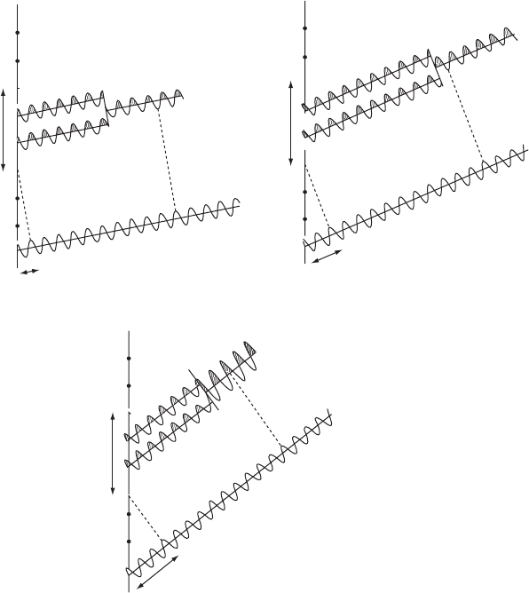
Calculating an electron-density map 89
Imaginary beam
Imaginary beam
Diffracted X rays
Diffracted X rays
Imaginary beam
Diffracted X rays
Origin
Origin
Chosen origin
a
a
a
1
1
2
2
2
1
l
2l
3l
Resultant out-of-phase
with imaginary beam
diffracted at origin.
Resultant in-phase
with imaginary beam
diffracted at origin.
Resultant out-of-phase
with imaginary beam
diffracted at origin.
100
Phase 180⬚
|F|=1.0
300
Phase 0⬚
|F|=2.0
200
Phase 180⬚
|F|=1.0
Fig. 6.1 Scattered waves and their relative phases.
A one-dimensional crystal with two atoms in the unit cell, one at x =
1
/
3
and the other at
x =
2
/
3
. Shown are the Bragg reflections (a) 100, (b) 200, and (c) 300 and their relationships
to an imaginary wave scattered at the chosen origin of the unit cell (which leads to
the “relative phase angle”). Note that the most intense of these three is the 300 Bragg
reflection.
sities). A unit cell containing two atoms, one at x =
1
/
3
and the other at
x =
2
/
3
, is used to illustrate how relative phases are derived. Compared
with an imaginary atom at the origin, the atom at x =
1
/
3
scatters for
a third order reflection with a path difference of one wavelength and
the atom at x =
2
/
3
scatters with a path difference of two wavelengths.
Thus both scatter in phase with the wave scattered at x = 0. However,
for the second order, the atom at x =
1
/
3
scatters X rays with a path
difference of 0.67 wavelengths from that scattered by the imaginary
atom at the origin, and the atom at x =
2
/
3
scatters with a path difference
of 1.33 wavelengths from the wave scattered at the origin. The resultant
wave is then (0.33 + 0.67)/2=0.50 wavelengths out of phase with the
wave scattered by the imaginary atom at the origin. Thus, in summing
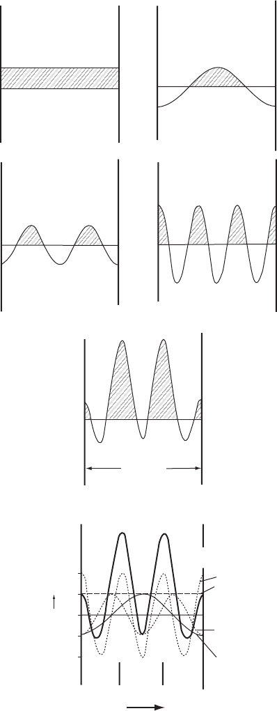
90 The phase problem and electron-density maps
|F(100)|= 1, a = 180º
100 negative
|F(000)|= 2, a =0º
000 always positive
|F(200)|= 1, a = 180º
200 negative
|F(300)|= 2, a =0º
300 positive
Summation
Unit cell
length
Total electron density
for h = 0 to 3
h =3
h =0
h =2
h =1
SUMMATION
SUMMATION
2/3 11/3
Vr(x)
0
−4
−2
0
2
4
x
Fig. 6.2 Fourier synthesis of the Bragg reflections from Figure 6.1.
The Fourier summation of density waves to give an electron-density map with peaks
at x = ±
1
/
3
.Atanypointx, y, z in the unit cell, volume V
c
, the electron density Ò( xyz)
may be calculated by use of Eqn. (6.5). The following data have been used for this one-
dimensional example:

Fourier transforms 91
density waves, as shown in Figure 6.2, the 300 wave has a relative phase
angle of 0
◦
and the 200 density wave has a relative phase angle of 180
◦
.
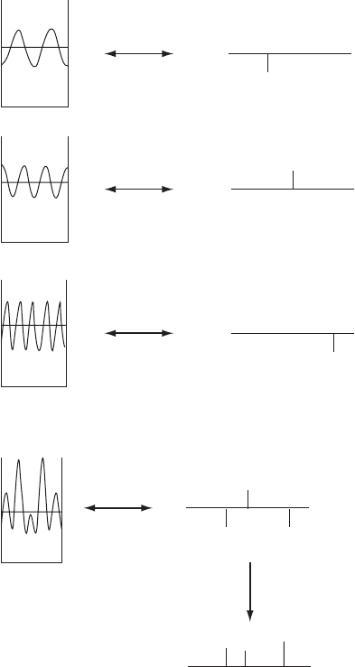
Fourier transforms
We have shown that the electron density Ò(xyz) (Eqn. 6.1) can be
expressed in an equation that involves the structure factors F(hkl)as
coefficients,
Ò =(1/ V) F e
−iˆ
(6.6)
It is also possible to express the structure factors in terms of the electron
density:
F = f e
iˆ
(6.7)
The relationship between these two is referred to as a Fourier trans-
form or Fourier inversion. These equations show that the structure
factor is the Fourier transform of the scattering density (electrons
in the molecule) sampled at the reciprocal lattice point hkl, while
the electron density is the Fourier transform of the structure fac-
tors (which contain their relative phases). The intensity at a par-
ticular point of the diffraction pattern of an object (a set of rela-
tive |F (hkl)|
2
values) is proportional to the square of the Fourier
transform of the object (with the distribution of matter in the object
described by Ò(x, y, z)). Examples of Fourier transforms are shown in
Figure 6.3, with electron density and density waves on the left and
structure factors, with their relative phases, shown on the right as
positive or negative (· =0
◦
or 180
◦
). Equation (6.6) or (6.7) (whichever
h −3 −2 −10123
|F(hkl)| 2112112
·(hkl)(
◦
) 0 180 180 0 180 180 0
cos[2π(hx − ·)] + cos 6πx −cos 4πx −cos 2πx +1 −cos 2πx −cos 4πx +cos6πx
Therefore Ò(x)=|F (000)|/ V
c
+(4cos6πx − 2cos4π x − 2cos2π x +2)/V
c
.
When h = 0, the function does not depend on x and so is a straight line (but drawn
with half its amplitude to conform to the electron-density map equation with positive
and negative values of h). The phase angle of this is necessarily 0
◦
. The function for
h =1is−cos 2π x, the negative sign resulting from the relative phase angle of 180
◦
,and
so forth. These functions are summed for each value of x to give the result shown by
the heavy solid line. It has peaks at x = ±
1
/
3
. Clearly, unless the phases were known,
it would not be possible to sum the waves correctly. This kind of calculation must be
made, with thousands of Bragg reflections, at each of many thousands of points to give a
complete electron-density map in three dimensions. Therefore high-speed computers are
essential. For a three-dimensional electron-density map it is not possible to plot heights
of peaks (because we have no fourth spatial dimension), and therefore contours of equal
electron density (or height) are drawn on sections through the three-dimensional map.
Atomic centers appear at the centers of areas of high electron density, which look like
circular mountains on a topographical map. The larger values of F dominate the Fourier
summation.
92 The phase problem and electron-density maps
0 1
2
3 456
0 123456
01234
5
6
0 1
2
3 4
5
6
0 123456 h
DENSITY WAVES
FT
FT
FT
-200 +300 - 500
- 500
- 200
+ 300
300+
200-
500-
Fourier
transform
Intensity
Phase information
lost
Unit-cell repeat
P(x)
Electron density
Sum
FT
BRAGG REFLECTIONS
SHOWING PHASE
(as a vertical displacement)
Fig. 6.3 Summing Fourier transforms.
Density waves for the 200, 300, and 500 Bragg reflections and their Fourier transforms.
When the columns are summed, the density waves (on the left) give the electron density
map, while their Fourier transforms (on the right) give the phases of the individual
density waves. When intensities are measured, the phase information is lost. Note: This
is a different structure from that in Figures 6.1 and 6.2.
is most appropriate) is used for the transformations. As will be seen
later, it is convenient to be able to move readily between real (electron
density) and reciprocal (structure factor) space, and this is how it is
done. For example, one may want to modify an electron-density map

Summing density waves to obtain an electron-density map 93
and calculate a new data set of structure factors for comparison with
experimental values or may calculate the theoretical electron density for
an atom or ion and then examine the atomic scattering factors relevant
to this density (as mentioned in Chapter 5). Alternatively, one may want
to change some (or all) of the structure factors and investigate the effect
of this on the electron-density map. The Fourier transform equations
make this possible.
Summing density waves to obtain an
electron-density map
We have emphasized the analogy between the action of a lens in col-
lecting and refocusing radiation to give an image of the scattering
matter, and the process of Fourier summation, a mathematical tech-
nique for forming an image by use of information about the ampli-
tudes and relative phases of the scattered waves. Fourier summation
techniques can be applied even when the waves cannot be refocused,
as in the X-ray experiment. With a lens the light waves are (ideally)
brought together with the same phases that they had when they left
the object; in the X-ray diffraction experiment these phases are usu-
ally not measurable, although if they can be found in some way,
then it is possible to calculate an electron-density map as shown in
Figures 6.3 and 6.4.
The individual waves in Eqn. (6.5) that are summed to give the
electron-density map are referred to, for convenience in this book, as
“density waves” (see Bijvoet et al., 1948). In other words, each term
|F (hkl)|cos[(2π(hx + ky+ lz) − ·(hkl)], calculated as a function of x, y,
and z, is a density wave, as illustrated in Figure 6.4. In effect, Eqn.
(6.5) could be rewritten to say that the electron density Ò(x, y, z) at a
point in space x, y, z is equal to the sum of these density waves. Thus each
Bragg reflection with its relative phase can be considered to produce a
density wave in the crystal, with an amplitude that can be derived from
the intensity of the Bragg reflection; the superposition of these density
waves, once their phases are known, produces the electron-density map
for the crystal:
Ò(xyz)=
1
V
c
F (000)
+2
∞
all density waves
F (hkl)
cos[2π(hx + ky+ lz) − ·(hkl)]
(6.8)
The determination of the phases of these density waves is the subject
of much of the rest of this book. But what is the wavelength of a
density wave and how is it related to the order (h, k, l) of the diffracted
beam? Their wavelengths depend on h, k,andl, not the wavelength
of the X rays that caused each Bragg reflection. A close examination
of Eqn. (6.5) shows that |F (hkl)| is modified by a cosine function
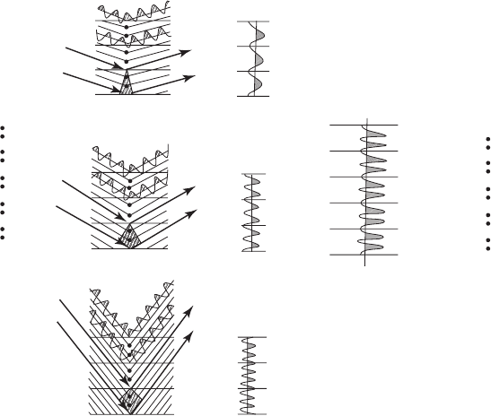
94 The phase problem and electron-density maps
100 density wave
100
“reflection”
200
“reflection”
300
“reflection”
300 density wave
(i)
(ii) (iii) (iv) (v)
200 density wave
Actual atomic
structure
Summation of density waves
to give electron density map
Actual atomic
structure
Fig. 6.4 Overview of X-ray diffraction.
Summary of the diffraction experiment, showing (i) the atomic structure (one-dimensional in this case); (ii) diffraction of X rays by the
crystal structure; (iii) density waves; (iv) summation of the density waves to give the electron-density map; and the result is an image
of the actual structure (v), which is the same as (i).
of (2π(hx + ky+ lz) − ·(hkl)); thus it becomes a periodic function of h,
k,andl. In the simple case (Figure 6.2) where k and l are both zero,
cos 2π( hx) is at a maximum value when x =1/ h; that is, this cosine term
has an apparent wavelength of a/ h (where a is the unit-cell length in the
x direction and x is expressed as a fraction of this dimension a).
In summary, the wavelengths of the density waves are d
hkl
= Î/2sinË,
their amplitudes are |F(hkl)|, and their phases are ·(hkl). For example,
thewavelengthofthe100densitywaveistherepeat distance a(= d
100
)
(see Figure 6.2), the wavelength of the 2 0 0 density wave is a/2 because
the second order of diffraction occurs at a sin Ë value twice that of the
first order, and so forth. For the 1 0 0 reflection, phase π, Eqn. 6.8 gives
the function cos [2πx + π] which is maximal at x =1/2 (see Figure 6.4).
These are the density waves that are summed to give the electron-
density map shown in Figure 6.2. “High resolution” implies a high
value of sin Ë and thus a small value for the effective wavelength of
the density wave; as we shall see later, high-resolution Bragg reflec-
tions (short wavelength density waves) are needed to provide high-
resolution images of molecules.
The density waves, derived by arguments such as these, are summed
as shown in Figures 6.2 and 6.4 to give the electron density of the
Summing density waves to obtain an electron-density map 95
Structure with correct phases (Molecule as line drawing)
Structure with second set of random phases (Molecule as line drawing)
Structure with first set of random phases (Molecule as line drawing)
Structure with third set of random phases (Molecule as line drawing)
y
x
y
x
y
x
y
x
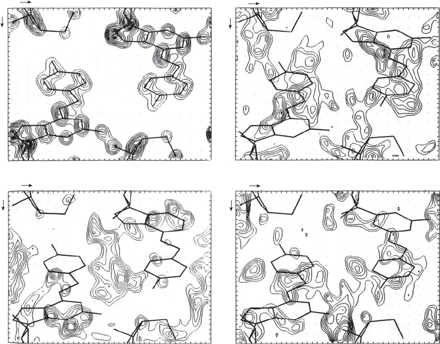
Fig. 6.5 Comparison of electron-density maps when the phases are correct and when they are incorrect and random.
In the computation of all maps shown here, the same |F ( hkl )| values but different phases were used. The upper left electron-density
map (a) is the correct result; the other three maps ((b) to (d)) have incorrect relative phases, and provide an incorrect electron-density
map. The phases of these three “random phase” maps were found by a computer program for random number generation. Since the
structure is noncentrosymmetric, the phase for each Bragg reflection could have any value between 0
◦
and 360
◦
.Ineachcase,the
molecular skeleton is shown by solid lines in the correct position, but it is clear that only the first map (top left) correctly represents
the true structure.
Courtesy H. L. Carrell.
structure, and the peaks in such a map correspond to the centers of
atoms. The importance of the phases in determining a structure is illus-
trated in Figure 6.5. Each of the four electron-density maps in this figure
has the same values of |F |, but differs in the phases used in the calcula-
tion. For clarity, the true crystal structure is indicated by a line diagram.
As can be seen, only the first map correctly gives peaks at atomic posi-
tions. An electron-density map with correct phases much more nearly
approximates the correct structure than does an electron-density map
with incorrect phases, even if each has the correct magnitudes for the
|F (hkl)|values. The analysis of electron-density and Patterson maps has
96 The phase problem and electron-density maps
benefited greatly from the improvements in computer graphics so that
now it is possible to view the three-dimensional map on a computer
screen and rotate and move it at will in order to obtain structural
information. However, automatic fitting of a three-dimensional model
structure to the electron-density map is now possible by computer
without any need for display (Lamzin et al. 2001; Oldfield, 2003).
An initial trial structure
At the start of a structure determination one does not know the
positions of all the atoms in the structure (for if one did, the structure
would probably not need to be investigated), but one can often deduce
an approximation to the correct structure. The calculated phases for
this initial (approximate) trial structure will provide a starting point for
structure determination. This trial structure may be one that completely
fills the unit cell or else it may be only a partial structure (even, for
example, one heavy atom). It is possible to calculate an approximation
to the true electron density by a three-dimensional Fourier summation
of the observed structure factor amplitudes, |F
o
|, with phases calculated
from an initial trial structure which may be only partially complete.
It has been found that the general features of an electron-density map
depend much more on the phase angles than on the structure factor
amplitudes. Therefore a map calculated with only approximately
correct phases will be an imperfect representation of the structure.
However, it is biased toward the correct structure because the observed
structure amplitudes |F
o
| were used in the calculation. By comparison
with a similar synthesis using the calculated amplitudes |F
c
|,oreven
more simply by computing the difference (|F
o
|−|F
c
|) to obtain a “dif-
ference synthesis”, one can deduce the changes in the model needed to
give better agreement with observation. The positions of some hitherto
unrecognized atoms may be indicated, and shifts in the positions of
some atoms already included will normally be suggested as well.
Correctness of the trial structure
Once the approximate positions and identities of all the atoms in the
asymmetric unit are known (that is, when the true crystal structure is
known), the amplitudes and phases of the structure factors can readily
be calculated (see Chapter 5). These calculated amplitudes, |F (hkl)
c
|,
may be compared with the observed amplitudes, |F (hkl)
o
|. If the struc-
tural model is a correct one and the experimentally observed data are
reasonably precise, the agreement should be good. The situation is
different for phases. The phases calculated for a trial structure cannot
be compared with observed phases, because normally phases are not

Correctness of the trial structure 97
observed; they depend on where the origin of the unit cell was chosen
to be.
One measure of the correctness of a structure is the so-called
discrepancy index (or reliability index or conventional residual), R,
defined as
R =
(
|
F
o
|
−
|
F
c
|
)
(
|
F
o
|
)
(6.9)
It is a measure of how closely the experimentally observed structure
factor amplitudes are matched by the values calculated for a proposed
trial structure. At present, R values in the range of 0.02 to 0.06 (alter-
natively described as 2 percent to 6 percent) are being quoted for the
most reliably determined structures of small molecules. An R value of
0.83 corresponds to a random centrosymmetric structure; that is, with
proper scaling a randomly incorrect structure with a center of symme-
try would give an R value of about 0.83 (0.59 for a noncentrosymmetric
crystal structure) (Wilson, 1950). A refinable trial structure may have an
R value between 0.25 and 0.35, or even somewhat higher. This value
will (hopefully) be decreased by methods described in Chapter 11 to a
much lower value. If one atom of high atomic number is present, the
initial trial value of R may be much lower because the position of this
atom can usually be determined reasonably well even at an early stage,
and a heavy atom normally dominates the scattering, as illustrated in
the atomic scattering factors in Figure 5.4a. If the trial structure is a
reasonable approximation to the correct structure, the R value goes
down appreciably as refinement proceeds.
The discrepancy index R is, however, only one measure of the pre-
cision (but not necessarily the accuracy) of the derived structure. It
denotes how well the calculated model fits the observed data. Many
complications can cause errors in the observed or calculated struc-
ture factors or both—for example, absorption of the X-radiation by
the crystal, or atomic scattering factors and temperature factors that
do not adequately describe the experimental situation. The fit of the
calculated structure factors to the observed ones may then be good,
but if the observations are systematically in error, the accuracy of the
derived structure may be low, despite an apparently high precision.
Hence care must be taken in interpreting R values. In general, the
lower the R value the better the structure determination, but if one or
more very heavy atoms are present, they may dominate the structure
factor calculation to such an extent that the contributions from light
atoms may not have noticeable effects on R, especially if the structure
has not been refined extensively. The positions of the light atoms may
then be significantly in error. Also the resolution of the data (i.e., the
maximum value of sin Ë/Î) must be taken into account in assessing the
meaning of an R value. A few grossly incorrect trial structures have
been refined to R values as low as 0.10. Fortunately this situation is not
common.