Gibilisco S. Teach Yourself Electricity and Electronics
Подождите немного. Документ загружается.

(c) A comparator
(d) A multiplexer/demultiplexer
8. Which type of digital IC is least susceptible to noise?
(a) Transistor-transistor logic
(b) Base-coupled logic
(c) Emitter-coupled logic
(d) N-channel-coupled logic
9. Which of the following is not a characteristic of CMOS chips?
(a) Sensitivity to damage by electrostatic discharge
(b) Low current demand
(c) Ability to work at high speed
(d) Ability to handle extremely high power
10. An absolute limit to the component density that can be achieved in IC technology is
determined by
(a) the maximum current levels needed.
(b) the maximum attainable impedance.
(c) the size of the semiconductor atoms.
(d) Forget it! There is no limit to the component density that can be achieved in IC
technology.
11. With a ROM chip,
(a) it is easier to read data from the device than to write data into it.
(b) it is more difficult to read data from the device than to write data into it.
(c) it is easy to read data from the device, and just as easy to write data into it.
(d) it is difficult to read data from the device, and equally difficult to write data into it.
12. With a RAM chip,
(a) it is easier to read data from the device than to write data into it.
(b) it is more difficult to read data from the device than to write data into it.
(c) it is easy to read data from the device, and just as easy to write data into it.
(d) it is difficult to read data from the device, and equally difficult to write data into it.
13. Which type of IC must be physically removed from the circuit to have its memory contents
changed?
(a) An EEPROM chip
(b) An EPROM chip
(c) An SRAM chip
(d) A DRAM chip
Quiz 501
14. With respect to memory, which of the following terms means that the data contents vanish if
power is removed from a chip?
(a) Volatility
(b) Component density
(c) Multiplexing
(d) Corruptibility
15. In terms of the maximum number of transistors on a single chip, how many orders of
magnitude larger is VLSI than MSI?
(a) Two
(b) Three
(c) Four
(d) Forget it! The maximum number of transistors on a VLSI chip is not larger, but smaller
than the maximum number of transistors on an MSI chip.
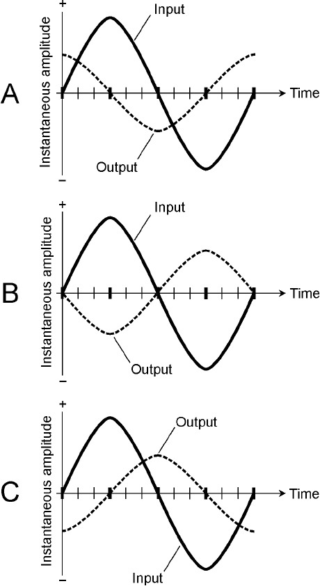
16. Which of the following illustrations in Fig. 28-9 shows the input and output of a
differentiator circuit?
(a) A
(b) B
(c) C
(d) None of them
17. Which of the following illustrations in Fig. 28-9 shows the input and output of an integrator
circuit?
(a) A
(b) B
(c) C
(d) None of them
18. Flip-flops are used to store data in
(a) timers.
(b) op amps.
(c) multiplexers.
(d) none of the above.
19. Capacitors are used to store data in
(a) timers.
(b) op amps.
(c) multiplexers.
(d) none of the above.
502 Integrated Circuits
20. The phase of a sine wave signal can be shifted 180° by
(a) applying the signal to the input of a timer.
(b) applying the signal to the inverting input of an op amp.
(c) applying the signal to the input of a flip-flop.
(d) applying the signal to the input of an SRAM chip.
Quiz 503
28-9 Illustration for Quiz
Questions 16 and 17.
ELECTRON TUBES, ALSO CALLED TUBES OR VALVES (IN ENGLAND), ARE USED IN SOME ELECTRONIC
equipment. In a tube, the charge carriers are free electrons that travel through space between elec-
trodes inside the device. This makes tubes fundamentally different from semiconductor devices, in
which charge carriers move among atoms in a solid medium.
Tube Forms
There are two basic types of electron tube: the vacuum tube and the gas-filled tube. As their names
imply, vacuum tubes have virtually all the gases removed from their envelopes. Gas-filled tubes con-
tain elemental vapor at low pressure.
Vacuum Tube
Vacuum tubes accelerate electrons to high speeds, resulting in large currents. This current can be fo-
cused into a beam and guided in a particular direction. The intensity and/or beam direction can be
changed with extreme rapidity, producing effects such as rectification, detection, oscillation, ampli-
fication, signal mixing, waveform displays, spectral displays, and video imaging.
Gas-Filled Tube
Gas-filled tubes have a constant voltage drop, no matter what the current. This makes them useful
as voltage regulators for high-voltage, high-current power supplies. Gas-filled tubes can withstand
conditions that would destroy semiconductor regulating devices. Gas-filled tubes emit infrared
(IR), visible light, and/or ultraviolet (UV). This property can be put to use for decorative lighting.
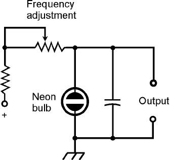
A small neon bulb can be employed to construct an AF relaxation oscillator (Fig. 29-1).
Diode Tube
Even before the year 1900, scientists knew that electrons could carry electric current through a vac-
uum. They also knew that hot electrodes emit electrons more easily than cool ones. These phenom-
504
29
CHAPTER
Electron Tubes
Copyright © 2006, 2002, 1997, 1993 by The McGraw-Hill Companies, Inc. Click here for terms of use.
ena were put to use in the first electron tubes, known as diode tubes, for the purpose of rectification.
Diode tubes are rarely used nowadays, although they can still be found in some power supplies that
are required to deliver several thousand volts for long periods at a 100 percent duty cycle (that is, con-
tinuous operation).
Electrodes in a Tube
In a tube, the electron-emitting electrode is the cathode. The cathode is usually heated by means of
a wire filament, similar to the glowing element in an incandescent bulb. The heat drives electrons
from the cathode. The cathode of a tube is analogous to the source of an FET, or to the emitter of
a bipolar transistor. The electron-collecting electrode is the anode, also called the plate. The plate is
the tube counterpart of the drain of an FET or the collector of a bipolar transistor. In most tubes,
intervening grids control the flow of electrons from the cathode to the plate. The grids are the coun-
terparts of the gate of an FET or the base of a bipolar transistor.
Directly Heated Cathode
In some tubes, the filament also serves as the cathode. This type of electrode is called a directly
heated cathode. The negative supply voltage is applied directly to the filament. The filament voltage
for most tubes is 6 V or 12 V dc. It is important that dc be used to heat the filament in this type of
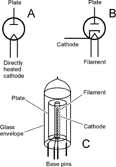
tube, because ac will tend to modulate the output. The schematic symbol for a diode tube with a di-
rectly heated cathode is shown in Fig. 29-2A.
Indirectly Heated Cathode
In many types of tubes, the filament is enclosed within a cylindrical cathode, and the cathode gets
hot from the IR radiated by the filament. This is an indirectly heated cathode. The filament normally
receives 6 V or 12 V ac or dc. In an indirectly heated cathode arrangement, ac does not cause mod-
ulation problems, as it can with a directly heated cathode tube. The schematic symbol for a diode
tube with an indirectly heated cathode is shown in Fig. 29-2B.
Because the electron emission in a tube depends on the filament or heater, tubes need a certain
amount of time to warm up before they can operate properly. This time can vary from a few seconds
Electrodes in a Tube 505
29-1 A neon bulb oscillator,
also known as a
relaxation oscillator.
(for a small tube with a directly heated cathode) to a couple of minutes (for massive power-amplifier
tubes with indirectly heated cathodes). The warm-up time for a large tube is about the same as the
boot-up time for a personal computer.
Cold Cathode
In a gas-filled tube, the cathode does not have a filament to heat it. Such an electrode is called a cold
cathode. Various chemical elements are used in gas-filled tubes. In fluorescent devices, neon, argon,
and xenon are common. In gas-filled voltage-regulator (VR) tubes, mercury vapor is used. In a
mercury-vapor VR tube, the warm-up period is the time needed for the elemental mercury, which
is a liquid at room temperature, to vaporize (approximately 2 minutes).
Plate
The plate, or anode, of a tube is a cylinder concentric with the cathode and filament, as shown in
Fig. 29-2C. The plate is connected to the positive dc supply voltage. Tubes operate at plate voltages
ranging from 50 V to more than 3 kV. These voltages are potentially lethal. Technicians unfamiliar
with vacuum tubes should not attempt to service equipment that contains them. The output of a
tube-type amplifier circuit is almost always taken from the plate circuit. The plate exhibits high im-
pedance for signal output, similar to that of an FET.
506 Electron Tubes
29-2 At A, schematic
symbol for diode tube
with directly heated
cathode. At B, symbol
for diode tube with
indirectly heated
cathode. At C,
simplified rendition of
the construction of a
diode tube.
Control Grid
The flow of current can be controlled by means of an electrode between the cathode and the plate.
This electrode, the control grid (or simply the grid ), is a wire mesh or screen that lets electrons pass
through. The grid impedes the flow of electrons if it is provided with a negative voltage relative to
the cathode. The greater the negative grid bias, the more the grid obstructs the flow of electrons
through the tube.
Triode Tube
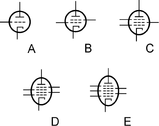
A tube with one grid is a triode. The schematic symbol is shown at A in Fig. 29-3. In this case the
cathode is indirectly heated; the filament is not shown. This omission is standard in schematics
showing tubes with indirectly heated cathodes. When the cathode is directly heated, the filament
symbol serves as the cathode symbol. The control grid is usually biased with a negative dc voltage
ranging from near 0 to as much as half the positive dc plate voltage.
Tetrode Tube
A second grid can be added between the control grid and the plate. This is a spiral of wire or a coarse
screen, and is called the screen grid or screen. This grid normally carries a positive dc voltage at 25 to
35 percent of the plate voltage.
The screen grid reduces the capacitance between the control grid and plate, minimizing the ten-
dency of a tube amplifier to oscillate. The screen grid can also serve as a second control grid, allow-
ing two signals to be injected into a tube. This tube has four elements, and is known as a tetrode. Its
schematic symbol is shown at B in Fig. 29-3.
Pentode Tube
The electrons in a tetrode can bombard the plate with such force that some of them bounce back,
or knock other electrons from the plate. This so-called secondary emission can hinder tube perfor-
Electrodes in a Tube 507
29-3 Schematic symbols for
vacuum tubes with
grids: triode (A),
tetrode (B), pentode
(C), hexode (D), and
heptode (E).
mance and, at high power levels, cause screen current so high that the electrode is destroyed. This
problem can be eliminated by placing another grid, called the suppressor grid or suppressor, between
the screen and the plate. The suppressor repels secondary electrons emanating from the plate, prevent-
ing most of them from reaching the screen. The suppressor also reduces the capacitance between the
control grid and the plate more than a screen grid by itself.
Greater gain and stability are possible with a pentode, or tube with five elements, than with a
tetrode or triode. The schematic symbol for a pentode is shown at C in Fig. 29-3. The suppressor is
often connected directly to the cathode.
Hexode and Heptode Tubes
In some older radio and TV receivers, tubes with four or five grids were sometimes used. These
tubes had six and seven elements, respectively, and were called hexode and heptode. The usual func-
tion of such tubes was signal mixing. The schematic symbol for a hexode is shown at D in Fig.
29-3; the symbol for a heptode is at E. You will not encounter hexodes and heptodes in modern
electronics, because solid-state components are used for signal mixing.
Interelectrode Capacitance
In a vacuum tube, the cathode, grid(s), and plate exhibit interelectrode capacitance that is the primary
limiting factor on the frequency range in which the device can produce gain. The interelectrode ca-
pacitance in a typical tube is a few picofarads. This is negligible at low frequencies, but at frequen-
cies above approximately 30 MHz, it becomes a significant consideration. Vacuum tubes intended
for use as RF amplifiers are designed to minimize this capacitance.
Circuit Configurations
The most common application of vacuum tubes is in amplifiers, especially in radio and television
transmitters at power levels of more than 1 kW. Some high-fidelity audio systems also employ vac-
uum tubes. In recent years, tubes have gained favor with some popular music bands. Some musi-
cians insist that “tube amps” provide richer sound than amplifiers using power transistors. There are
two basic vacuum-tube amplifier circuit arrangements: the grounded-cathode configuration and the
grounded-grid configuration.
Grounded Cathode
Figure 29-4 is a simplified schematic diagram of a grounded-cathode circuit using a triode tube.
This circuit is the basis for many tube-type RF power amplifiers and audio amplifiers. The input
impedance is moderate, and the output impedance is high. Impedance matching between the am-
plifier and the load can be obtained by tapping a coil in the output circuit, or by using a transformer.
Grounded Grid
Figure 29-5 shows a basic grounded-grid RF amplifier circuit. The input impedance is low, and the
output impedance is high. The output impedance is matched by the same means as with the
grounded-cathode arrangement. The grounded-grid configuration requires more driving (input)
power than the grounded-cathode scheme. A grounded-cathode amplifier might produce 1 kW of
508 Electron Tubes
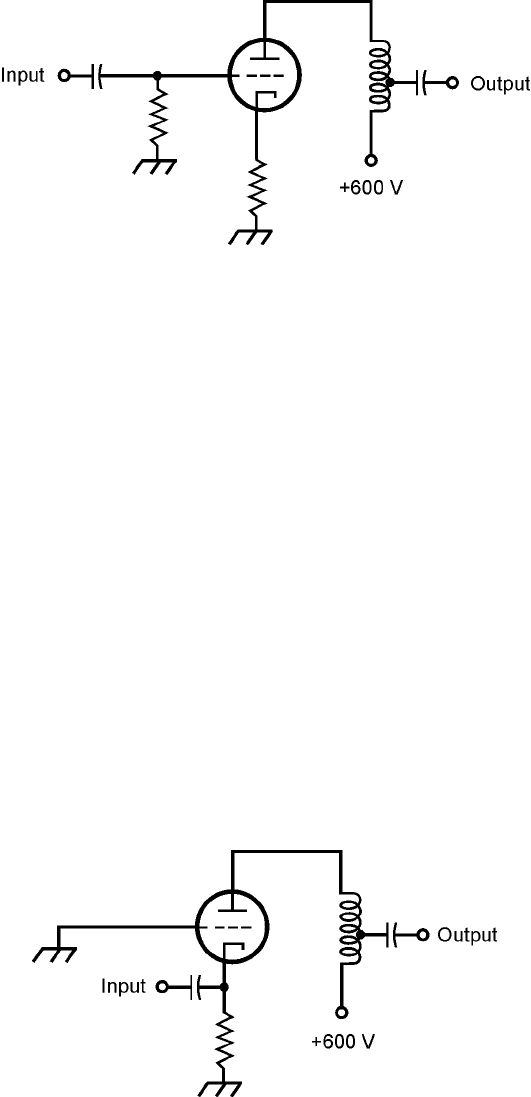
RF output for 10-W input, but a grounded-grid amplifier needs 50 W to 100 W of drive to pro-
duce 1 kW of RF output. A grounded-grid amplifier has a significant advantage, however: it is less
likely to break into unwanted oscillation than a grounded-cathode circuit.
Plate Voltage
The plate voltages (+600 V dc) in the circuits of Figs. 29-4 and 29-5 are given as examples. The am-
plifiers shown could produce 75- to 150-W signal output provided they receive sufficient drive and
are properly biased. An amplifier rated at 1-kW output would require a plate voltage of +2 kV dc to
+5 kV dc. In high-power radio and TV broadcast transmitters producing in excess of 50-kW RF
output, even higher dc plate voltages are used.
Cathode-Ray Tubes
Many TV receivers, and some desktop computer monitors, use cathode-ray tubes (CRTs). So do
older oscilloscopes, spectrum analyzers, and radar sets.
Electron Beam
In a CRT, a specialized cathode called an electron gun emits an electron beam that is focused and ac-
celerated as it passes through positively charged anodes. The beam then strikes a glass screen whose
inner surface is coated with phosphor. The phosphor glows visibly, as seen from the face of the CRT,
because of the effect of the high-speed electrons striking it.
Cathode-Ray Tubes 509
29-5 Simplified schematic
diagram of a
grounded-grid RF
amplifier circuit using
a triode tube.
29-4 Simplified schematic
diagram of a
grounded-cathode RF
amplifier circuit using
a triode tube.
The beam scanning pattern is controlled by magnetic or electrostatic fields. One field causes the
beam to scan rapidly across the screen in a horizontal direction. Another field moves the beam ver-
tically. When complex waveforms are applied to the electrodes that produce the deflection of the
electron beam, a display pattern results. This pattern can be the graph of a signal wave, a fixed
image, an animated image, a computer text display, or any other type of visible image.
Electromagnetic CRT
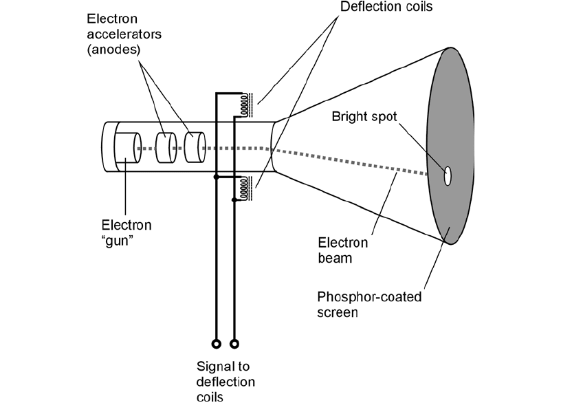
A simplified cross-sectional drawing of an electromagnetic CRT is shown in Fig. 29-6. There are two
sets of deflecting coils, one for the horizontal plane and the other for the vertical plane. (To keep the
illustration reasonably clear, only one set of deflecting coils is shown.) The greater the current in the
coils, the greater the intensity of the magnetic field, and the more the electron beam is deflected.
The electron beam is bent at right angles to the magnetic lines of flux.
In an oscilloscope, the horizontal deflecting coils receive a sawtooth waveform. This causes the
beam to scan, or sweep, at a precise, adjustable speed across the screen from left to right as viewed
from in front. After each timed left-to-right sweep, the beam returns, almost instantly, to the left
side of the screen for the next sweep. The vertical deflecting coils receive the waveform to be ana-
lyzed. This waveform makes the electron beam move up and down. The combination of vertical and
horizontal beam motion produces a display of the input waveform as a function of time.
510 Electron Tubes
29-6 Simplified cross-sectional rendition of an electromagnetic CRT.
