Gersten J.I., Smith F.W. The Physics and Chemistry of Materials
Подождите немного. Документ загружается.

474 CHARACTERIZATION OF MATERIALS
where v
0
z
is the velocity on the right and v
z
is the velocity on the left. The Fermi–Dirac
factors guarantee that the tunneling electron will come from an occupied sample state
and tunnel into a vacant stylus state. The form of the barrier potential energy is
Uz D E
F
1
C e
1
C
2
1
V
z
D
,W22.142
where z D 0 at the sample surface and image potential corrections are neglected. At
low temperatures the Fermi factors may be replaced by unit step functions (i.e.,
functions). If the functions are expanded to first order in V, the expression becomes
J
z
D
2
2
3
dkv
z
Pv
z
eV
1
2
υE E
F
1
, W22.143
which may be expressed in terms of the density of states at the Fermi level:
J
z
D
eV
v
F
2
;E
F
1
hcos iP D
e
2
Vv
F
4
;E
F
1
P. W22.144
Here
v
z
has been replaced by v
F
cos and the average value of cos in the forward
direction is equal to
1
2
. The tunneling integral is readily computed, and finally, a formula
for the particle current density is obtained:
J
z
V D
eV
4
;E
F
v
0
F
exp
4D
p
2m
3¯h
e
1
3/2
e
2
3/2
e
1
e
2
.W22.145
The quantity
v
0
F
is the Fermi velocity for the tunneling probe. The exponential falloff
with tunneling distance is expected as well as the dependence on some average barrier
height.
The actual value of the electric current is given by I DeAJ
z
,whereA is a char-
acteristic area. For the case of a stylus tip with radius of curvature R, one may expect
A ³ R
2
. Equation (W22.145) is not completely correct. In reality, one should use the
local density of states rather than the bulk density of states. The local density of states
varies from position to position in directions parallel to the surface and reflects the
variations in local charge density of the surface bonds. Therefore, as one rasters the
surface under the tip, the tunneling current will vary from position to position.
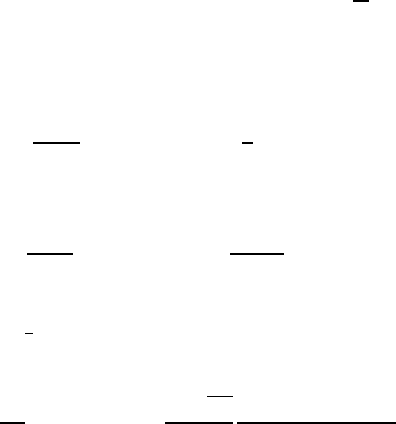
An example of an STM picture of the surface of Si(100) is presented in Fig. W22.42.
It shows, with atomic resolution, a Si(100) 2 ð1 surface with a Na overlayer.
W22.24 Lateral-Force Microscope and Surface Force Apparatus
A variant of the atomic-force microscope, called the lateral-force microscope (LFM),
can measure the shear stress on a microscopic stylus that is slid across a surface
(Fig. W22.43). It is sensitive to forces as small as 1 pN. The stylus, which constitutes
one of the solids (commonly diamond or Si
3
N
4
), is supported by a flexible cantilever
that can be deflected as the stylus rubs against the other surface. By measuring the
bending of the cantilever, one may determine the normal force exerted on it by the
stylus. By measuring the torsion of the cantilever, information concerning the frictional
force is obtained. These measurements are made by reflecting a beam of light from the
back of the cantilever and recording the position of the reflected spot on a screen. The
CHARACTERIZATION OF MATERIALS 475
3x2-Na
(a) (b)
Si(100)2x1
or c(4x2)
2x3-Na
Figure W22.42. Micrograph of the Si(100) surface with an overlayer of Na atoms. [From
A. A. Saranin et al., Phys. Rev. B, 58, 4972 (1998). Copyright 1998 by the American Physical
Society.]
Figure W22.43. Lateral force microscope (LFM). A light beam is reflected off a cantilever and
strikes an array of photodetectors. The flexure and torsion of the cantilever are related to the
normal and friction forces.
solid lying beneath the stylus is attached to a piezoelectric crystal stage. By applying
time-varying potential differences across this crystal, the sample may be rastered back
and forth beneath the stylus. Thus a friction map may be generated.
By coating the stylus with a self-assembled monolayer (SAM) of organic molecules,
it is possible to sensitize the stylus so that it will respond differently to different adsor-
bates on the other solid. This is because the chemical specificity of the intermolecular
interactions determines the friction force. It was recently found that friction can be
both anisotropic and asymmetric when the monolayer consists of tilted molecules.
†
The
asymmetry refers to moving the stylus in the direction of the molecular tilt compared
with against it.
The surface force apparatus (SFA) is a device with two atomically flat parallel mica
plates. The width of the separation may be reduced to nm dimensions. Lubricants are
†
M. Liley et al., Science, 280, 273 (1998).

476 CHARACTERIZATION OF MATERIALS
placed in the gap and the plates are slid past each other. Evidence for the formation
of well-defined liquid layers is found when the gap distance is smaller than 10 nm.
The viscosity rises very rapidly as the gap distance is reduced. One finds evidence
for the formation of two-dimensional glassy solids within these layers if the layers
are very thin (e.g., four molecules thick). As the lubricant is sheared, these layers are
deformed elastically and then may release the strain energy by slipping or melting
when a critical shear stress is reached. The resulting stick-slip motion is reminiscent
of the mechanism believed to produce seismic earthquakes. The sudden slip motions
are also believed to peel material off the surfaces, thereby producing delamination
wear. Wear is the general term given to the change of geometry of the surfaces and
the removal of material from them as a result of friction. In polymer applications it
is found that the threshold for substantial wear is correlated with the product P
v,in
accordance with Eq. (W19.39). The value is referred to as the P
v limit. For example,
for polycarbonate and Teflon, the P
v limits are 0.01 and 0.06 MPa
.
m/s, respectively,
for
v D 0.5 m/s at room temperature.
Another device that is used to study the friction of lubricants is the quartz-crystal
microbalance (QCM). The damping of vibrations (i.e., the Q of the quartz crystal plate)
is influenced by the viscosity of the lubricant with which it is in contact.
TRANSPORT MEASUREMENTS
In Chapter 7 electrical-transport properties such as the electrical resistivities and the
Hall coefficients of materials have been introduced. Some elementary thermal and ther-
moelectric properties are also discussed. In the following two sections some methods
for measuring these properties are reviewed.
W22.25 Electrical Resistivity and Hall Effect
The simplest method for measuring resistivity involves the use of a cylindrical sample
of material of length L and cross-sectional area A. The resistance R is measured and the
resistivity is given by ; D RA/L. The accuracy of the measurement is limited by the
geometric measurements and the ability to control fringing fields. A simple geometrical
arrangement for measuring the Hall coefficient is given in Fig. 7.1 and discussed in
Section 7.3.
For a large sample of material with a planar surface, the four-contact method may
be employed to measure ;. Suppose that the material occupies the half-space z<0.
Place four contacts at four points on the surface at the locations defined by the vectors
r
A
, r
B
, r
C
,andr
D
. The contacts are placed close together so the distance between them
is much less than the distance to the edges of the surface. If a current I is injected into
contact A, it will set up an electrostatic potential field
A
r D ;I/2jr r
A
j within
the material. Similarly, if one draws a current I out of contact B, the potential field is
given by
B
r D;I/2jr r
B
j. When the current is injected at A and removed
at B, these potentials are superimposed to give r D
A
r
B
r. The difference
in potential is then measured between points C and D. The resistance is
R
CD,AB
D
V
CD,AB
I
D
;
2
1
r
CA
1
r
CB
1
r
BA
C
1
r
DB
,W22.146
where r
CA
Djr
C
r
A
j, and so on.
CHARACTERIZATION OF MATERIALS 477
BA
CD
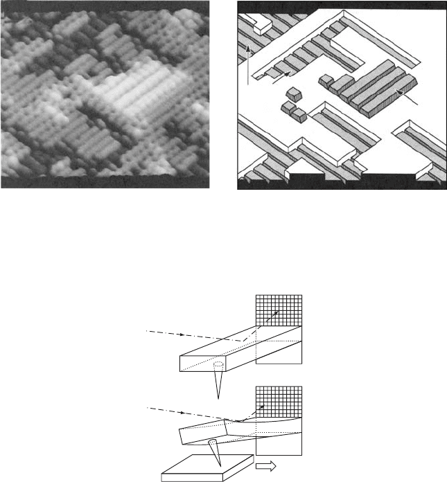
Figure W22.44. Clover-shaped sample for the van der Pauw method of measuring the resistivity
or the Hall coefficient.
The van der Pauw method
†
extends this method to two dimensions and permits one
to measure the resistivity and Hall coefficient for a thin sample of material. It will be
assumed that there is isotropy in the plane of the slab. Four fine electrodes, labeled
A, B, C, and D, are attached to the boundaries of a slab of thickness d.Theshape
of the sample is unimportant, as long as it has no holes in it (i.e., it must be simply
connected). (This may be proven by the method of conformal transformations using
complex-variable theory. It will not be derived here.) A typical geometry that is used
is illustrated in Fig. W22.44. In the resistivity case two measurements are made. First
a current I is driven from C to D and the voltage V
AB,CD
is measured across electrodes
A and B. The resistance R
AB,CD
is computed by the formula R
AB,CD
D V
AB,CD
/I.The
measurement is repeated with a current driven from D to A and the voltage measured
across B and C. The resistivity is given implicitly by the formula
expR
AB,CD
d/; C expR
BC,DA
d/; D 1.W22.147
The method may be generalized to anisotropic samples.
‡
The Hall coefficient R
H
is determined by measuring the change in the resistance
R
BD,AC
when a magnetic induction B is imposed perpendicular to the slab. The
formula is
R
H
D d
R
BD,AC
B
.W22.148
From a measurement of the Hall voltage the sign of the carrier may be determined.
W22.26 Thermopower, Peltier Coefficient, and Thermal Conductivity
A system in thermal equilibrium obeys the first law of thermodynamics, given by
Eq. (WA.1), TdS D dU C PdV dN. When the system is driven slightly out of
equilibrium, current densities are produced. These include the particle-current density,
J, and the energy-current density, J
U
. Consider the case where the charged carriers are
electrons, so the particle current density is proportional to the electrical-current density
(i.e., J
E
DeJ). The driving forces for J
E
include the electric field, E Dr,aswell
as the gradient in the chemical potential and the gradient in the temperature. The same
forces drive J
U
. In place of the energy-current density, the first law of thermodynamics
is used to define the heat-current density, J
Q
, in terms of the chemical potential:
J
Q
D TJ
S
J
U
J,W22.149
†
L. J. van der Pauw, Philips Res. Rep., 13, 1 (1959).
‡
L. J. van der Pauw, Philips Res. Rep., 16, 195 (1961).

478 CHARACTERIZATION OF MATERIALS
where J
S
is interpreted as an entropy-current density. For weak driving forces the
current densities are expressed as linear combinations of the driving forces:
J
E
D e
L
11
T
r e C eL
12
r
1
T
,W22.150a
J
Q
D
L
21
T
r e C L
22
r
1
T
,W22.150b
where L
ij
are coefficients. Onsager proved (in general) that L
12
D L
21
so there are three
independent coefficients. An example of the Onsager relations has been encountered
when the transport properties of metals were studied in Section 7.5.
The significance of the L
ij
coefficients may be obtained by examining special cases:
1. If T and are constant in space, then
J
E
D e
2
L
11
T
E,W22.151
so D e
2
L
11
/T. The coefficient L
11
is therefore proportional to the electrical
conductivity.
2. If the heat current is measured for the case where there is no electric current
(i.e., J
E
D 0), it is found that
J
Q
D
L
11
L
22
L
2
12
L
11
T
2
rT D5 rT, W22.152
where 5 is the thermal conductivity.
3. In the absence of an electric current, an electric field is established in the sample,
that is,
eE Dr
L
12
TL
11
rT. W22.153
The electromotive force is given by
ε D
"
E · dl D
1
e
"
dl · r
"
Qdl · rT, W22.154
where Q DL
12
/eTL
11
is called the absolute thermoelectric power of the mate-
rial. (The symbol Q is used here rather than S so as not to confuse it with the
entropy.) The first term on the right-hand side may be written as
#
d and is
zero. The second term may be written as
#
QdT.
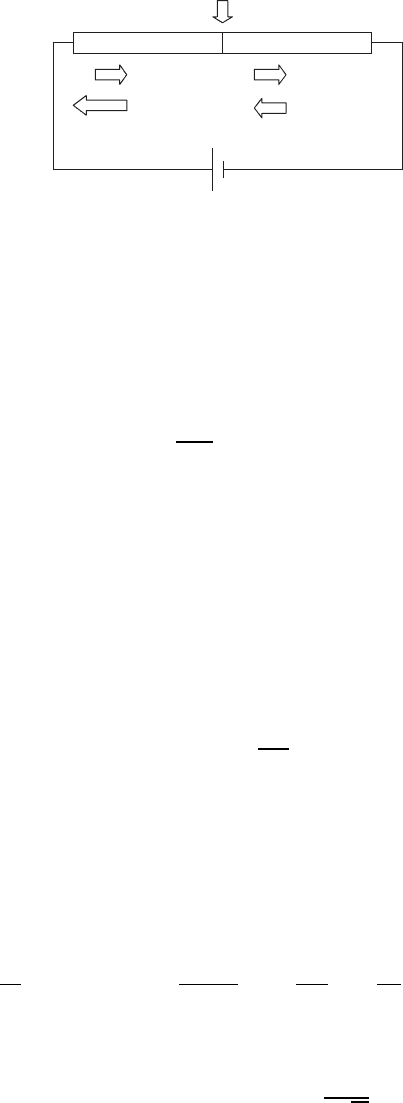
Consider an experimental arrangement such as is shown in Fig. W22.45, consisting
of two conductors, labeled A and B, with absolute thermoelectric powers Q
A
and
Q
B
, respectively. Let a voltmeter be inserted in one of the conductors to measure the
electromotive force ε. Label the temperatures at the left and right junctions T
J
and
T
J
C T, respectively, and the temperature at the voltmeter T
J
C T
0
. It is assumed
that T − T
J
and T
0
− T
J
.Then
ε DQ
A
[T
J
C T T
J
C T
0
] Q
B
[T
J
T
J
C T]
Q
A
[T
J
C T
0
T
J
]
D Q
B
Q
A
T. W22.155
CHARACTERIZATION OF MATERIALS 479
B
V
T
J
T
J
+ ∆T
'
T
J
+ ∆T
AA
Figure W22.45. Arrangement for measuring the absolute thermopower.
Thus the difference in the thermopowers is the voltage per unit temperature difference:
Q
B
Q
A
D
ε
T
.W22.156
A four-probe technique is used to measure the thermopower. Thermocouple ther-
mometers are placed at the left and right junctions to measure T
J
and T
J
C T,and
the difference of the temperatures is taken to obtain T. The voltage leads are placed
across the gap, as shown in Fig. W22.45. In measuring the thermopower one places
both the sample and thermometer in vacuum, to eliminate convective heat channels.
They are also shielded with highly reflecting surfaces to minimize radiative losses.
(The same techniques are used in the design of a thermos bottle.) The voltage could
be measured using a potentiometer connected to a sensitive galvanometer. Very small
thermocouples, connected to very fine leads, are employed as thermometers.
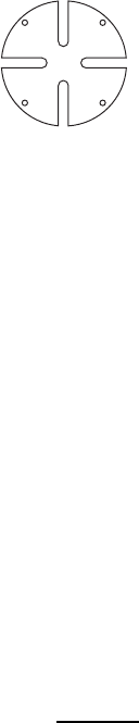
Thermocouples are thermometers that produce an electromotive potential related to
the temperature at the junction. A typical thermocouple is illustrated in Fig. W22.46.
Two conductors, A and B, form a junction that acts as the temperature probe. The
other wires are each connected to identical conductors, labeled C. The AC and BC
junctions are each held at the same standard temperature, T
0
. A mixture of ice and
water at atmospheric temperature is often used to set T
0
D 0
°
C. The other ends of
the C wires are connected to a galvanometer and a potentiometer at room temper-
ature. Typical thermocouples involve the use of copper versus constantan, chromel
versus alumel, chromel versus constantan, iron versus constantan, and platinum versus
platinum–rhodium.
A
B
C
C
G
T
0
T
T
R
Figure W22.46. Thermocouple arrangement.
480 CHARACTERIZATION OF MATERIALS
AB
J
E
J
E
∆J
Q
J
Q
B
J
Q
A
Figure W22.47. Peltier effect.
The Peltier effect involves creating a junction of two dissimilar conductors and
passing an electrical current through it. The electrical current is the same in each
conductor. Assume that the temperature is held constant. The situation is illustrated
in Fig. W22.47. In the absence of a temperature gradient term, the heat current is
proportional to the electric current:
J
Q
D
L
12
eL
11
J
E
DQTJ
E
.W22.157
Since Q is discontinuous from one conductor to the other, this implies that a heat
transfer must take place at the junction. The heat extracted at the junction from the
environment is given by
J
Q
D J
B
Q
J
A
Q
DTQ
B
Q
A
J
E
BA
J
E
,W22.158
where
BA
is called the Peltier coefficient. Thus the Peltier coefficient is defined as
the heat extracted per unit current. It may be determined from a measurement of the
thermopower through the relation
BA
DT
ε
T
.W22.159
There are a number of ways to measure the thermal conductivity. They often may
be classified as transient measurements or steady-state measurements. An example of a
transient measurement is the following. Take a rod of length L initially at temperature
T
0
.Att D 0 place the left end of the rod in contact with a thermal bath at temperature
T
1
. Measure the temperature of a point on the rod at position x for times t>0. The
thermal diffusion equation is
r
· J
Q
C
∂u
∂t
DrÐ5 rT C
∂;cT
∂t
D5
∂
2
T
∂x
2
C ;c
∂T
∂t
D 0,W22.160
where it is assumed that 5 is independent of T. The solution to Eq. (W22.160) is
Tx, t D T
1
T
1
T
0
erf
x
2
p
at
,W22.161

CHARACTERIZATION OF MATERIALS 481
where ; is the density, c the specific heat, and the thermal diffusivity is a D 5/;c.
The error function erf(x) is defined in Chapter W6. The rise of T(x,t) with time at a
fixed x is compared to this formula, and a value for a is determined. The value of c is
obtained from a calorimetry experiment.
In the steady-state measurements simple geometrical arrangements are chosen and
heat is supplied to the material at a known rate. The temperature differential is
measured. For example, if a rod of length L is connected to a heater supplying a
known heat flux J
Q
, and the temperature difference T is measured between two
points along the rod a distance x apart, then 5 D J
Q
x/T.
A preferable geometrical arrangement involves the use of concentric cylinders. A
cylindrical heater of length L and radius R
1
is surrounded by a hollow sample of
material of the same length, with inner radius R
1
and outer radius R
2
. Heat is delivered
by the electrical heater at a known rate, H. Thermocouples are used to measure the
temperature difference T between the inner and outer surfaces of the sample. The
thermal conductivity is then given by
5 D
H
2L T
ln
R
2
R
1
.W22.162
MAGNETIC MEASUREMENTS
The magnetic properties of materials are discussed in Chapter 9, and a number of
magnetic materials are studied in Chapter 17. In this section some of the measure-
ment techniques for characterizing magnetic materials are described. They include
use of the Foner magnetometer, the Faraday balance, and the ac bridge. The SQUID
magnetometer is discussed in Chapter 16.
W22.27 Foner Magnetometer
The Foner magnetometer is used to measure the magnetization of a small sample
of magnetic material. When measuring the saturation magnetization the shape of the
sample is not important. For nonsaturation conditions a spherical sample is used so
that the orientation of the sample is not relevant. The sample is placed on a reed and
is made to vibrate in the presence of a coil of wire. For this reason the apparatus is
also known as the vibrating-sample magnetometer (VSM). Alternatively, the coil may
be vibrated in the presence of the magnetic sample. In either case an ac electromotive
force is established in the coil which is readily measured. From this measurement the
magnetization may be determined.
A formula for the EMF may be obtained by considering a coil with a current I in the
neighborhood of the sample and neglecting resistance effects. Let L be the inductance
of the coil in the absence of the sample. The energy of the system is
U D
1
2
LI
2
0
m · H,W22.163
where H is the magnetic field intensity and m is the magnetic moment of the sample.
It will be assumed that H D H
O
k and that m D MV,whereM is the magnetization and
482 CHARACTERIZATION OF MATERIALS
V is the volume of the sample. The energy of the system will be constant, so
dU
dt
D 0 D LI
dI
dt
0
MV
dH
dt
.W22.164
Use LI D N,whereN the number of turns in the coil and is the magnetic flux
through the coil. Assume that H D Hz and write dH/dt D
v
z
dH/dz,wherev
z
is the
z component of the velocity of the sample. From Faraday’s law the EMF is given by
ε DNd/dt DLdI/dt. Thus
ε D
0
MVv
z
1
I
dH
dz
.W22.165
For a harmonic oscillation of the sample, z D A cos ωt,whereA is the amplitude
(typically ³ 1 mm) and ω is the frequency (typically corresponding to ³ 100 Hz).
Therefore,
εt D
0
ωMVA
I
dH
dz
sin ωt. W22.166
From a measurement of the amplitude of the EMF and the mechanical motion, together
with knowledge of the sensitivity of the instrument, jdH/dz/Ij, and the volume of the
sample, one may determine the magnetization of the sample. The sensitivity function
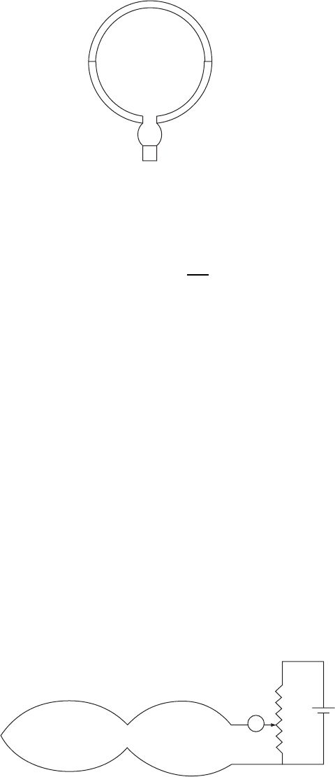
depends on the geometry. For example, consider the ideal case of two coils of wire
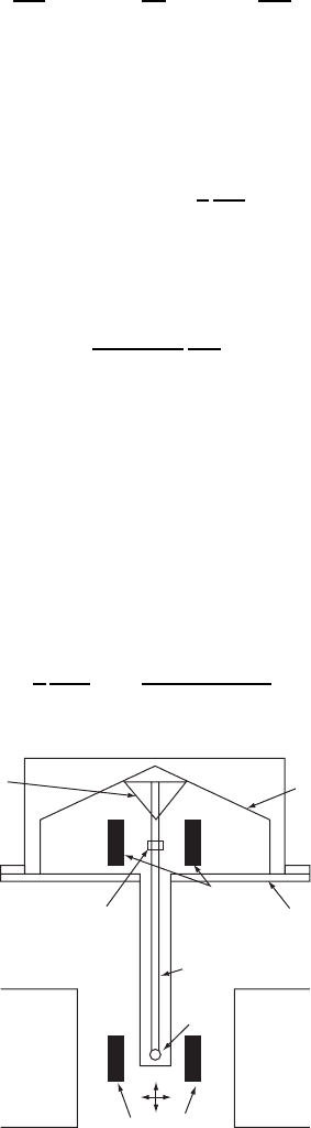
of radius R separated by a coaxial distance 2D. A sketch of the Foner magnetometer
is given in Fig. W22.48. Some external source (not shown), such as a loudspeaker, is
used to establish vibrations in the reed to which the sample is attached. The coils are
wound so that the currents generated in the coils will flow in opposite directions. Near
the center of symmetry one finds the sensitivity
1
I
dH
z
dz
D
3NDR
2
2R
2
C D
2
5/2
.W22.167
Conical paper
cup support
Magnet
pole
Magnet
pole
Sample coils
z
x
Reference
sample
Reference
coils
Drinking straw
Sample
Loudspeaker
transducer
Metal
container
Figure W22.48. Foner magnetometer. (Adapted from S. Foner, J. Appl. Phys., 79, 4740 (1996).
Copyright 1996 by the American Institute of Physics.)
CHARACTERIZATION OF MATERIALS 483
The maximum sensitivity occurs when R D 2D and has the value jdH/dz/IjD
96N/5R
2
p
5. The sensitivity grows with the number of turns (which could typically
be ³ 25,000) and falls off inversely as the square of the radius.
The Foner magnetometer readily measures magnetic moments on the order of 10
10
A·m
2
at liquid-nitrogen temperatures, to reduce the thermal noise. The instrument is
generally calibrated in terms of a known ferromagnetic material, such as Ni. Magne-
tizations are measured relative to the calibration standard.
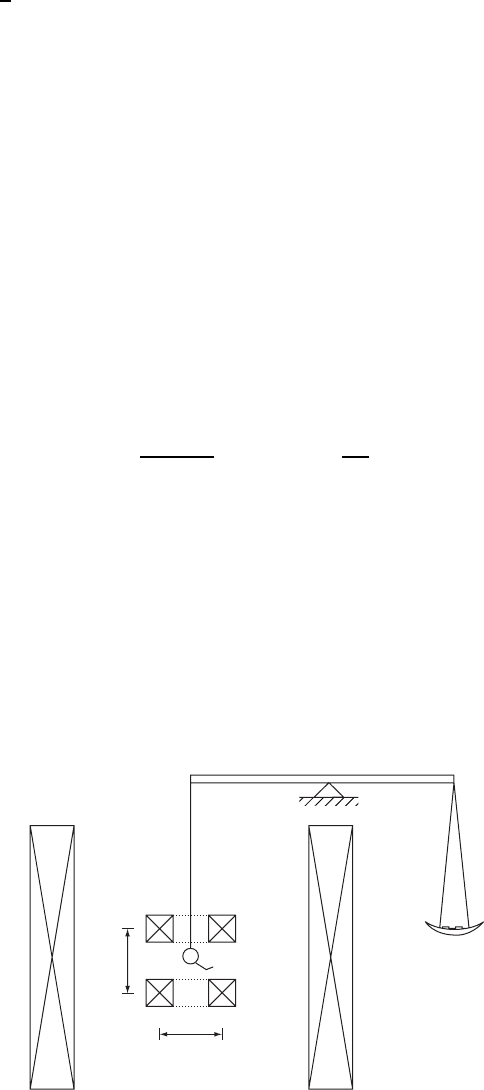
W22.28 Faraday Balance
The Faraday balance permits one to measure the magnetization of a sample
in a magnetic field. The technique is illustrated in Fig. W22.49. A solenoidal
superconducting magnet establishes a magnetic field intensity H
0
in the axial direction
which magnetizes the sample, the magnetization being MH
0
. Note that this uniform
magnetic field does not produce a net force on the sample. Weights are placed on the
right-hand side of the balance equal to the weight of the sample to maintain equilibrium.
Then an inhomogeneous magnetic field H is established by the smaller pair of coils.
The coils are arranged as shown in Fig. W22.49. The magnetic force in the axial
direction is given by
F
z
D
∂m
· B
∂z
D MH
0
V
0
∂H
∂z
D W, W22.168
where V is the volume of the sample. The additional weight W is placed on the right-
hand side to counterbalance the magnetic force. In practice, an analytical microbalance
is adapted to serve as the balance. The field gradient is vertical. The radius, R, equals
the separation between the coils, D, as in the Helmoltz coil arrangement, but the
currents are in opposite directions so that a uniform gradient dH/dz is established.
W22.29 AC Bridge
The complex frequency-dependent magnetic permeability of a material,
r
ω D
1
ω C i
2
ω, may be measured by means of the ac bridge method. One prepares a
Sample
D
2R
Figure W22.49. Faraday balance.