FitzGerald J., Dennis A., Durcikova A. Business Data Communications and Networking
Подождите немного. Документ загружается.


3.2 CIRCUITS 85
3.1
NASA’S GROUND COMMUNICATIONS
NETWORK
MANAGEMENT
FOCUS
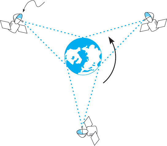
NASA’s communications network is extensive
because its operations are spread out around the
world and into space. The main Deep Space Net-
work is controlled out of the Jet Propulsion Labo-
ratory (JPL) in California. JPL is connected to the
three main Deep Space Communications Centers
(DSCCs) that communicate with NASA spacecraft.
The three DSCCs are spread out equidistantly
around the world so that one will always be able
to communicate with spacecraft no matter where
they are in relation to the earth: Canberra, Aus-
tralia; Madrid, Spain; and Goldstone, California.
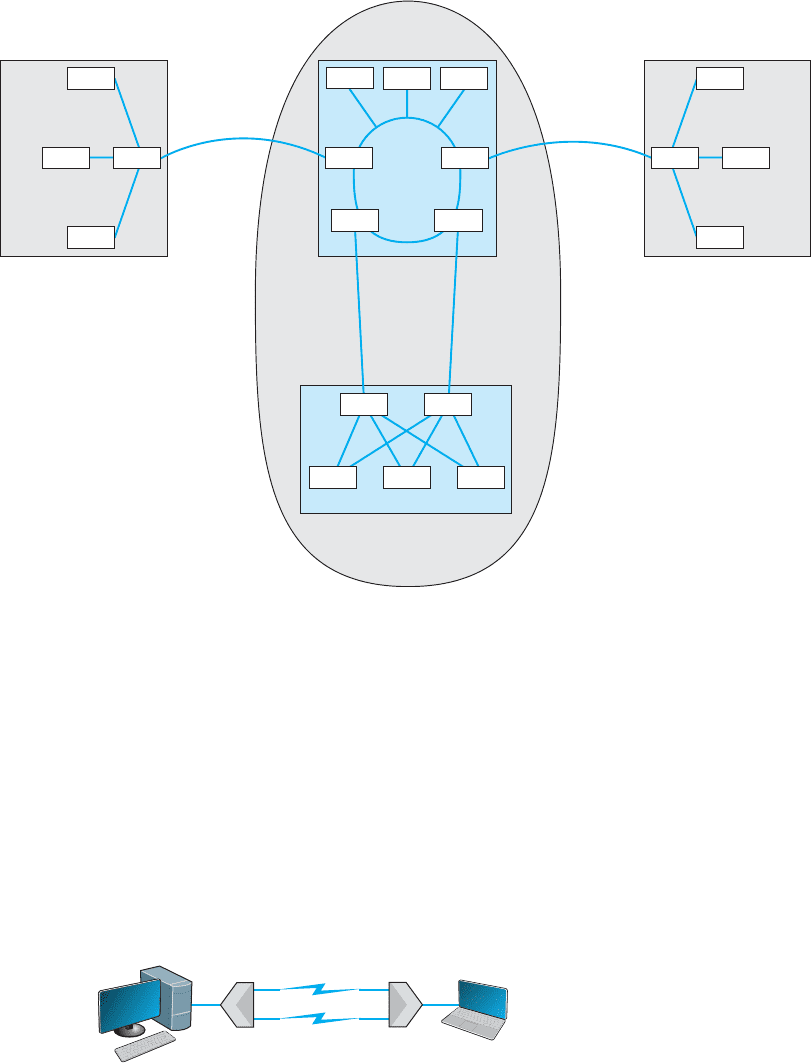
Figure 3.7 shows the JPL network. Each DSCC
has four large-dish antennas ranging in size from
85 to 230 feet (26 to 70 meters) that communi-
cate with the spacecraft. These send and receive
operational data such as telemetry, commands,
tracking, and radio signals. Each DSCC also sends
and receives administrative data such as email,
reports, and Web pages, as well as telephone
calls and video.
The three DSCCs and JPL use Ethernet local
area networks (LANs) that are connected to mul-
tiplexers that integrate the data, voice, and video
signals for transmission. Satellite circuits are used
between Canberra and JPL and Madrid and JPL.
Fiber-optic circuits are used between JPL and
Goldstone.
Dense WDM (DWDM) is a variant of WDM that further increases the capacity of
WDM by adding TDM to WDM. DWDM permits up to 40 simultaneous circuits, each
transmitting up to 10 Gbps, giving a total network capacity in one fiber-optic cable of 400
Gbps (i.e., 400 billion bits per second). Remember, this is the same physical cable that
until recently produced only 622 Mbps; all we’ve changed are the devices connected to it.
Dense wavelength division multiplexing is a relatively new technique, so it will con-
tinue to improve over the next few years. Today, DWDM systems have been announced
that provide 128 circuits, each at 10 Gbps (1.28 terabits per second [1.28 Tbps]) in one
fiber cable. Experts predict that DWDM transmission speeds should reach 25 Tbps (i.e.,
25 trillion bits per second) within a few years (and possibly 1 petabit [Pbps], or 1 mil-
lion billion bits per second)—all on that same single fiber-optic cable that today typically
provides 622 Mbps. Once we reach these speeds, the most time-consuming part of the
process is converting from the light used in the fiber cables into the electricity used in
the computer devices used to route the messages through the Internet. Therefore, many
companies are now developing computer devices that run on light, not electricity.
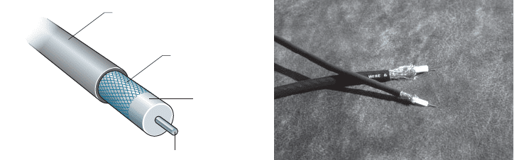
Inverse Multiplexing Multiplexing uses one high-speed circuit to transmit a set of
several low-speed circuits. It can also be used to do the opposite. Inverse multiplexing
(IMUX) combines several low-speed circuits to make them appear as one high-speed
circuit to the user (Figure 3.8).
One of the most common uses of IMUX is to provide T1 circuits for WANs. T1 cir-
cuits provide data transmission rates of 1.544 Mbps by combining 24 slower-speed
circuits (64 Kbps). As far as the users are concerned, they have access to one high-
speed circuit, even though their data actually travel across a set of slower circuits. T1
and other circuits are discussed in Chapter 8.
Until recently, there were no standards for IMUX. If you wanted to use IMUX,
you had to ensure that you bought IMUX circuits from the same vendor so both clients
86 CHAPTER 3 PHYSICAL LAYER
Australia
Canberra
Deep Space Communications
Center
Goldstone
Deep Space Communications
Center
Satellite
Satellite
Madrid
Deep Space Communications
Center
800 kbps
256 kbps
16
Lines
MUX
Data VideoVoice
MUX
Spain
Jet Propulsion
Laboratory
United States
800 kbps
256 kbps
16
Lines
1.5 mbps 18 Lines 256 kpbs
MUX
MUX
MUX
MUX
Data
Video
Voice
Video
Voice
Data
MUX
Video
Voice
Data
MUX
FIGURE 3.7 NASA’s Deep Space Communications Centers ground communications
network. MUX = multiplexer
or hosts could communicate. Several vendors have recently adopted the BONDING
standard (Bandwidth on Demand Interoperability Networking Group). Any IMUX
circuit that conforms to the BONDING standard can communicate with any other IMUX
circuit that conforms to the same standard. BONDING splits outgoing messages from one
client or host across several low-speed telephone lines and combines incoming messages
from several telephone lines into one circuit so that the client or host “thinks” it has a
faster circuit.
The most common use for BONDING is for room-to-room videoconferencing. In
this case, organizations usually have the telephone company install six telephone lines
into their videoconferencing room that are connected to the IMUX. (The telephone lines
Server
Inverse
multiplexer
Inverse
multiplexer
Client
computer
FIGURE 3.8 Inverse
multiplexer

3.2 CIRCUITS 87
3.2 GET MORE BANDWIDTH FOR LESS
MANAGEMENT
FOCUS
Upstart network provider Yipes is among the
first to offer network services based on wave-
length division multiplexing (WDM). It offers cir-
cuits that range from 1 Mbps up to 1 Gbps in
1-Mbps increments and costs anywhere between
10 percent and 80 percent of the cost of traditional
services.
SOURCE: Yipes.com.
are usually 64-Kbps ISDN telephone lines; see Chapter 8 for a description of ISDN.)
When an organization wants to communicate with another videoconferencing room that
has a similar six-telephone-line IMUX configuration, the first IMUX circuit uses one
telephone line to call the other IMUX circuit on one of its telephone lines. The two
IMUX circuits then exchange telephone numbers and call each other on the other five
lines until all six lines are connected. Once the connection has been established, the
IMUX circuits transmit data over the six lines simultaneously, thus giving a total data
rate of 6 × 64 Kbps = 384 Kbps.
3.2.4 How DSL Transmits Data
The reason for the limited capacity on voice telephone circuits lies with the telephone and
the switching equipment at the telephone company offices. The actual twisted pair wire
in the local loop is capable of providing much higher data transmission rates. Digital
Subscriber Line (DSL) is one approach to changing the way data are transmitted in
the local loop to provide higher-speed data transfer. DSL is a family of techniques that
combines analog transmission and FDM to provide a set of voice and data circuits. There
are many different types of DSL, so many in fact that DSL is sometimes called xDSL,
where the x is intended to represent one of the many possible flavors. Chapter 9 examines
the different types of DSL.
With DSL, a DSL modem (called customer premises equipment [CPE])is
installed in the customer’s home or office and another DSL modem is installed at the
telephone company switch closest to the customer’s home or office. The modem is
first an FDM device that splits the physical circuit into three logical circuits: a standard
voice circuit used for telephone calls, an upstream data circuit from the customer to the
telephone switch, and a downstream data circuit from the switch to the customer. TDM
is then used within the two data channels to provide a set of one or more individual
channels that can be used to carry different data. A combination of amplitude and
phase modulation is used in the data circuits to provide the desired data rate (the exact
combination depends on which flavor of DSL is used).
2
One version of DSL called
G.Lite ASDL provides one voice circuit, a 1.5-Mbps downstream circuit, and a 384-Kbps
upstream channel.
2
More information can be found from the DSL forum (www.dslforum.org) and the ITU-T (www.itu.int) under
standard G.992.

88 CHAPTER 3 PHYSICAL LAYER
3.3 COMMUNICATION MEDIA
The medium (or media, if there is more than one) is the physical matter or substance that
carries the voice or data transmission. Many different types of transmission media are
currently in use, such as copper (wire), glass or plastic (fiber-optic cable), or air (radio,
microwave, or satellite). There are two basic types of media. Guided media arethosein
which the message flows through a physical media such as a twisted pair wire, coaxial
cable, or fiber-optic cable; the media “guides” the signal. Wireless media arethosein
which the message is broadcast through the air, such as microwave or satellite.
In many cases, the circuits used in WANs are provided by the various common
carriers who sell usage of them to the public. We call the circuits sold by the common
carriers communication services. Chapter 8 describes specific services available in North
America. The following sections describe the medium and the basic characteristics of
each circuit type, in the event you were establishing your own physical network, whereas
Chapter 8 describes how the circuits are packaged and marketed for purchase or lease
from a common carrier. If your organization has leased a circuit from a common carrier,
you are probably less interested in the media used and more interested in whether the
speed, cost, and reliability of the circuit meets your needs.
3.3.1 Twisted Pair Cable
One of the most commonly used types of guided media is twisted pair cable, insulated
pairs of wires that can be packed quite close together (Figure 3.9). The wires usually
are twisted to minimize the electromagnetic interference between one pair and any other
pair in the bundle. Your house or apartment probably has a set of two twisted pair wires
(i.e., four wires) from it to the telephone company network. One pair is used to connect
your telephone; the other pair is a spare that can be used for a second telephone line.
The twisted pair cable used in LANs are usually packaged as four sets of pairs as shown
in Figure 3.9, whereas bundles of several thousand wire pairs are placed under city
streets and in large buildings. The specific types of twisted pair cable used in LANs,
such as Cat 5e and Cat 6, are discussed in Chapter 6.
FIGURE 3.9 Category 5e
twisted pair wire
Source: © Jason/Alamy
3.3 COMMUNICATION MEDIA 89
Insulator
Second conductor
Outer cylindrical shell
Inner conductor
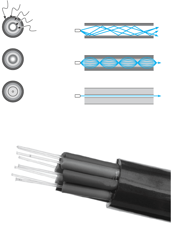
FIGURE 3.10 Coaxial cables. Thinnet and Thicknet Ethernet cables (right) and
cross-sectional view (left)
Source: © Tony Freeman/PhotoEdit
3.3.2 Coaxial Cable
Coaxial cable is a type of guided media that is quickly disappearing (Figure 3.10).
Coaxial cable has a copper core (the inner conductor) with an outer cylindrical shell for
insulation. The outer shield, just under the shell, is the second conductor. Because they
have additional shielding provided by their multiple layers of material, coaxial cables
are less prone to interference and errors than basic low-cost twisted pair wires. Coaxial
cables cost about three times as much as twisted pair wires but offer few additional
benefits other than better shielding. One can also buy specially shielded twisted pair
wire that provides the same level of quality as coaxial cable but at half its cost. For this
reason, few companies are installing coaxial cable today, although some still continue to
use existing coaxial cable that was installed years ago.
3.3.3 Fiber-Optic Cable
Although twisted pair is the most common type of guided media, fiber-optic cable also
is becoming widely used. Instead of carrying telecommunication signals in the traditional
electrical form, this technology uses high-speed streams of light pulses from lasers or
LEDs (light-emitting diodes) that carry information inside hair-thin strands of glass called
optical fibers. Figure 3.11 shows a fiber-optic cable and depicts the optical core, the
cladding (metal coating), and how light rays travel in optical fibers.
The earliest fiber-optic systems were multimode, meaning that the light could reflect
inside the cable at many different angles. Multimode cables are plagued by excessive
signal weakening (attenuation) and dispersion (spreading of the signal so that different
parts of the signal arrive at different times at the destination). For these reasons, early
multimode fiber was usually limited to about 500 meters. Graded-index multimode fiber
attempts to reduce this problem by changing the refractive properties of the glass fiber so
that as the light approaches the outer edge of the fiber, it speeds up, which compensates
for the slightly longer distance it must travel compared with light in the center of the
fiber. Therefore, the light in the center is more likely to arrive at the same time as the
light that has traveled at the edges of the fiber. This increases the effective distance to
just under 1,000 meters.
90 CHAPTER 3 PHYSICAL LAYER
Core
Buffer
Aramid yarn
Jacket
Cladding
Step index (multimode)
Graded index (multimode)
Single mode
Source
Light
rays
FIGURE 3.11 Fiber-optic
cable
Source: © Hugh Threlfall/Alamy
Single-mode fiber-optic cables transmit a single direct beam of light through a
cable that ensures the light reflects in only one pattern, in part because the core diameter
has been reduced from 50 microns to about 5 to 10 microns. This smaller-diameter
core allows the fiber to send a more concentrated light beam, resulting in faster data
transmission speeds and longer distances, often up to 100 kilometers. However, because
the light source must be perfectly aligned with the cable, single-mode products usually

3.3 COMMUNICATION MEDIA 91
use lasers (rather than the LEDs used in multimode systems) and therefore are more
expensive.
Fiber-optic technology is a revolutionary departure from the traditional copper
wires of twisted pair cable or coaxial cable. One of the main advantages of fiber optics is
that it can carry huge amounts of information at extremely fast data rates. This capacity
makes it ideal for the simultaneous transmission of voice, data, and image signals. In
most cases, fiber-optic cable works better under harsh environmental conditions than do
its metallic counterparts. It is not as fragile or brittle, it is not as heavy or bulky, and it
is more resistant to corrosion. Also, in case of fire, an optical fiber can withstand higher
temperatures than can copper wire. Even when the outside jacket surrounding the optical
fiber has melted, a fiber-optic system still can be used.
3.3.4 Radio
One of the most commonly used forms of wireless media is radio; when people used
the term wireless, they usually mean radio transmission. When you connect your laptop
into the network wirelessly, you are using radio transmission. Radio data transmission
uses the same basic principles as standard radio transmission. Each device or computer
on the network has a radio receiver/transmitter that uses a specific frequency range that
does not interfere with commercial radio stations. The transmitters are very low power,
designed to transmit a signal only a short distance, and are often built into portable
computers or handheld devices such as phones and personal digital assistants. Wireless
technologies for LAN environments, such as IEEE 802.11n, are discussed in more detail
in Chapter 7.
3.3
M
UNICH AIRPORT PROVIDES
WIRELESS HOTSPOTS
MANAGEMENT
FOCUS
Munich is Germany’s second-largest commercial
airport, handling over 23 million passengers per
year. It began offering wireless Internet access
in its terminal buildings and main concourse in
October 2001 and was the first wireless local area
network provider to give users a choice of Internet
Service Providers (ISP).
Travelers can use their home or work ISP
when on the move, greatly simplifying access and
billing. ISPs, which will benefit from increased loy-
alty and revenues, are already planning to use the
pioneering multi-service provider concept else-
where, so ultimately users may be able to travel
wherever they want without having to change ISP
or pay additional fees.
The hotspots are located throughout the
airport. Users simply have to turn on their
wireless-equipped computers and they will imme-
diately have access to the network. If they are not
existing customers of one of the offered ISPs,
they can choose to access the Internet by paying
¤5.00–¤8.00 per hour, depending upon the ISP.
SOURCE: ‘‘Munich Airport Uses Cisco Technology
to Break New WiFi Ground with the World’s First
Multiple ISP Hotspot’’ www.cisco.com, and
‘‘Wireless LAN pilot project a success. Up to 3,000
users a month tap in to wireless Internet access,’’
www.munich-airport.de.
92 CHAPTER 3 PHYSICAL LAYER
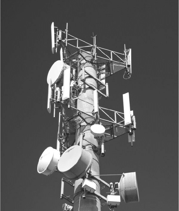
3.3.5 Microwave
Microwave transmission is an extremely high-frequency radio communication beam
that is transmitted over a direct line-of-sight path between any two points. As its name
implies, a microwave signal is an extremely short wavelength, thus the word micro
wave. Microwave radio transmissions perform the same functions as cables. For example,
point A communicates with point B via a through-the-air microwave transmission path,
instead of a copper wire cable. Because microwave signals approach the frequency of
visible light waves, they exhibit many of the same characteristics as light waves, such
as reflection, focusing, or refraction. As with visible light waves, microwave signals
can be focused into narrow, powerful beams that can be projected over long distances.
Just as a parabolic reflector focuses a searchlight into a beam, a parabolic reflector also
focuses a high-frequency microwave into a narrow beam. Towers are used to elevate the
radio antennas to account for the earth’s curvature and maintain a clear line-of-sight path
between the two parabolic reflectors; see Figure 3.12.
FIGURE 3.12 A
microwave tower. The round
antennas are microwave an-
tennas and the straight anten-
nas are cell phone antennas.
Source: Matej, Pribelsky listock photo
3.3 COMMUNICATION MEDIA 93
This transmission medium is typically used for long-distance data or voice trans-
mission. It does not require the laying of any cable, because long-distance antennas with
microwave repeater stations can be placed approximately 25 to 50 miles apart. A typical
long-distance antenna might be 10 feet wide, although over shorter distances in the inner
cities, the dish antennas can be less than 2 feet in diameter. The airwaves in larger cities
are becoming congested because so many microwave dish antennas have been installed
that they interfere with one another.
3.3.6 Satellite
Satellite transmission is similar to microwave transmission except instead of transmis-
sion involving another nearby microwave dish antenna, it involves a satellite many miles
up in space. Figure 3.13 depicts a geosynchronous satellite. Geosynchronous means that
the satellite remains stationary over one point on the earth. One disadvantage of satellite
transmission is the propagation delay that occurs because the signal has to travel out into
space and back to earth, a distance of many miles that even at the speed of light can be
noticeable. Low earth orbit (LEO) satellites are placed in lower orbits to minimize pro-
pogation delay. Satellite transmission is sometimes also affected by raindrop attenuation
when satellite transmissions are absorbed by heavy rain. It is not a major problem, but
engineers need to work around it.
Satellite revolving at
the same speed as
the earth's rotation
FIGURE 3.13 Satellites in
operation

94 CHAPTER 3 PHYSICAL LAYER
3.4
SATELLITE COMMUNICATIONS
IMPROVE PERFORMANCE
MANAGEMENT
FOCUS
Boyle Transportation hauls hazardous materials
nationwide for both commercial customers and
the government, particularly the U.S. Depart-
ment of Defense. The Department of Defense
recently mandated that hazardous materials con-
tractors use mobile communications systems with
up-to-the-minute monitoring when hauling the
department’s hazardous cargoes.
After looking at the alternatives, Boyle real-
ized that it would have to build its own system.
Boyle needed a relational database at its oper-
ations center that contained information about
customers, pickups, deliveries, truck location, and
truck operating status. Data are distributed from
this database via satellite to an antenna on each
truck. Now, at any time, Boyle can notify the
designated truck to make a new pickup via the
bidirectional satellite link and record the truck’s
acknowledgment.
Each truck contains a mobile data terminal con-
nected to the satellite network. Each driver uses
a keyboard to enter information, which transmits
the location of the truck. These satellite data are
received by the main offices via a leased line from
the satellite earth station.
This system increased productivity by an
astounding 80% over two years; administration
costs increased by only 20%.
3.3.7 Media Selection
Which media are best? It is hard to say, particularly when manufacturers continue
to improve various media products. Several factors are important in selecting media
(Figure 3.14).
•
The type of network is one major consideration. Some media are used only for
WANs (microwaves and satellite), whereas others typically are not (twisted pair,
Guided Media
Network
Type
Transmission
Distance
Media Cost Security Error Rates Speed
Twisted Pair LAN Low Short Good Low Low-high
Coaxial Cable LAN Moderate Short Good Low Low-high
Fiber Optics Any High Moderate-long Very good Very low High-very high
Radiated Media
Network
Type
Transmission
Distance
Media Cost Security Error Rates Speed
Radio LAN Low Short Poor Moderate Moderate
Microwave WAN Moderate Long Poor Low-moderate Moderate
Satellite WAN Moderate Long Poor Low-moderate Moderate
FIGURE 3.14 Media summary. BN = backbone network; LAN = local area network;
WAN = wide area network