FitzGerald J., Dennis A., Durcikova A. Business Data Communications and Networking
Подождите немного. Документ загружается.

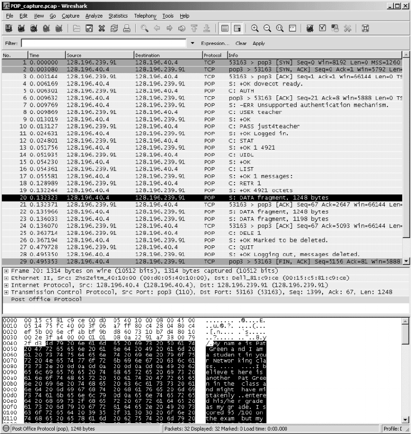
HANDS-ON ACTIVITY 2C 75
FIGURE 2.23 POP packets in Wireshark
CHAPTER3
PHYSICAL LAYER
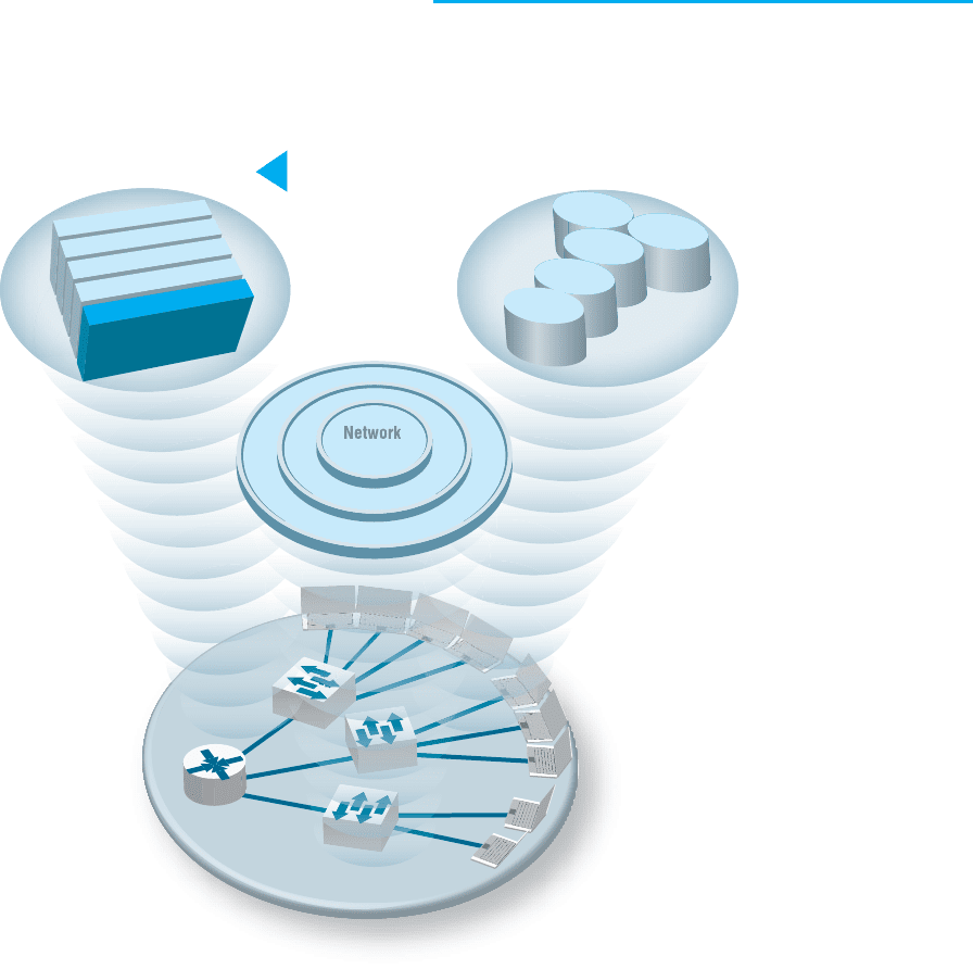
The Three Faces of Networking
The Three Faces of Networking
Fundamental Concepts Network Technologies
Network Management
S
ecurit
y
N
e
t
w
o
r
k
D
e
s
i
g
n
N
e
t
w
o
r
k
M
a
n
a
g
e
m
e
n
t
Application layer
Network layer
Data Link layer
Physical layer
LAN
WLAN
Backbone
WAN
Internet
Transport layer
CHAPTER OUTLINE 77
THE PHYSICAL layer (also called layer 1) is the physical con-
nection between the computers and/or devices in the network. This chapter
examines how the physical layer operates. It describes the most commonly
used media for network circuits and explains the basic technical concepts
of how data is actually transmitted through the media. Three different
types of transmission are described: digital transmission of digital computer
data; analog transmission of digital computer data; and digital transmission
of analog voice data. You do not need an engineering-level understanding of
the topics to be an effective user and manager of data communication appli-
cations. It is important, however, that you understand the basic concepts,
so this chapter is somewhat technical.
OBJECTIVES
▲
Be familiar with the different types of network circuits and media
Understand digital transmission of digital data
Understand analog transmission of digital data
Understand digital transmission of analog data
Be familiar with analog and digital modems
Be familiar with multiplexing
CHAPTER OUTLINE
▲
3.1 INTRODUCTION
3.2 CIRCUITS
3.2.1 Circuit Configuration
3.2.2 Data Flow
3.2.3 Multiplexing
3.2.4 How DSL Transmits Data
3.3 COMMUNICATION MEDIA
3.3.1 Twisted Pair Cable
3.3.2 Coaxial Cable
3.3.3 Fiber-Optic Cable
3.3.4 Radio
3.3.5 Microwave
3.3.6 Satellite
3.3.7 Media Selection
3.4 DIGITAL TRANSMISSION OF DIGITAL DATA
3.4.1 Coding
3.4.2 Transmission Modes
3.4.3 Digital Transmission
3.4.4 How Ethernet Transmits Data
3.5 ANALOG TRANSMISSION OF DIGITAL
DATA
3.5.1 Modulation
3.5.2 Capacity of a Circuit
3.5.3 How Modems Transmit Data
3.6 DIGITAL TRANSMISSION OF ANALOG
DATA
3.6.1 Translating from Analog to Digital
3.6.2 How Telephones Transmit Voice
Data
3.6.3 How Instant Messenger Transmits
Voice Data
3.6.4 Voice over Internet Protocol (VoIP)
3.7 IMPLICATIONS FOR MANAGEMENT

78 CHAPTER 3 PHYSICAL LAYER
3.1 INTRODUCTION
This chapter examines how the physical layer operates. The physical layer is the net-
work hardware including servers, clients, and circuits, but in this chapter we focus on
the circuits and on how clients and servers transmit data through them. The circuits
are usually a combination of both physical media (e.g., cables, wireless transmissions)
and special-purpose devices that enable the transmissions to travel through the media.
Special-purpose devices such as hubs, switches, and routers are discussed in Chapter 6
and 8.
The word circuit has two very different meanings in networking, and sometimes it
is hard to understand which meaning is intended. Sometimes, we use the word circuit to
refer to the physical circuit—the actual wire—used to connect two devices. In this case,
we are referring to the physical media that carry the message we transmit, such as the
twisted pair wire used to connect a computer to the LAN in an office. In other cases, we
are referring to a logical circuit used to connect two devices, which refers to the transmis-
sion characteristics of the connection, such as when we say a company has a T1 connec-
tion into the Internet. In this case, T1 refers not to the physical media (i.e., what type of
wire is used) but rather to how fast data can be sent through the connection.
1
Often, each
physical circuit is also a logical circuit, but as you will see in the section on multiplexing,
sometimes it is possible to have one physical circuit—one wire—carry several separate
logical circuits, or to have one logical circuit travel over several physical circuits.
There are two fundamentally different types of data that can flow through the
circuit: digital and analog. Computers produce digital data that are binary, either on
or off, 0 or 1. In contrast, telephones produce analog data whose electrical signals are
shaped like the sound waves they transfer; they can take on any value in a wide range
of possibilities, not just 0 or 1.
Data can be transmitted through a circuit in the same form they are produced.
Most computers, for example, transmit their digital data through digital circuits to print-
ers and other attached devices. Likewise, analog voice data can be transmitted through
telephone networks in analog form. In general, networks designed primarily to transmit
digital computer data tend to use digital transmission, and networks designed primarily
to transmit analog voice data tend to use analog transmission (at least for some parts of
the transmission).
Data can be converted from one form into the other for transmission over network
circuits. For example, digital computer data can be transmitted over an analog telephone
circuit by using a modem. A modem at the sender’s computer translates the computer’s
digital data into analog data that can be transmitted through the voice communication
circuits, and a second modem at the receiver’s end translates the analog transmission
back into digital data for use by the receiver’s computer.
Likewise, it is possible to translate analog voice data into digital form for trans-
mission over digital computer circuits using a device called a codec. Once again, there
1
Don’t worry about what a T1 circuit is at this point. All you need to understand is that a T1 circuit is a
specific type of circuit with certain characteristics, the same way we might describe gasoline as being unleaded
or premium. We discuss T1 circuits in Chapter 8.

3.2 CIRCUITS 79
are two codecs, one at the sender’s end and one at the receiver’s end. Why bother to
translate voice into digital? The answer is that digital transmission is “better” than ana-
log transmission. Specifically, digital transmission offers five key benefits over analog
transmission:
•
Digital transmission produces fewer errors than analog transmission. Because the
transmitted data is binary (only two distinct values), it is easier to detect and correct
errors.
•
Digital transmission permits higher maximum transmission rates. Fiber-optic cable,
for example, is designed for digital transmission.
•
Digital transmission is more efficient. It is possible to send more data through a
given circuit using digital rather than analog transmission.
•
Digital transmission is more secure because it is easier to encrypt.
•
Finally, and most importantly, integrating voice, video, and data on the same circuit
is far simpler with digital transmission.
For these reasons, most long-distance telephone circuits built by the telephone companies
and other common carriers over the past decades use digital transmission. In the future,
most transmissions (voice, data, and video) will be sent digitally.
Regardless of whether digital or analog transmission is used, transmission requires
the sender and receiver to agree on two key parameters. First, they have to agree on the
symbols that will be used: what pattern of electricity, light, or radio wave will be used
to represent a 0 and a 1. Once these symbols are set, the sender and receiver have to
agree on the symbol rate: How many symbols will be sent over the circuit per second?
Analog and digital transmissions are different, but both require a commonly agreed on
set of symbols, and a symbol rate.
In this chapter, we first describe the basic types of circuits and examine the different
media used to build circuits. Then we explain how data are actually sent through these
media using digital and analog transmission.
3.2 CIRCUITS
3.2.1 Circuit Configuration
Circuit configuration is the basic physical layout of the circuit. There are two funda-
mental circuit configurations: point-to-point and multipoint. In practice, most complex
computer networks have many circuits, some of which are point-to-point and some of
which are multipoint.
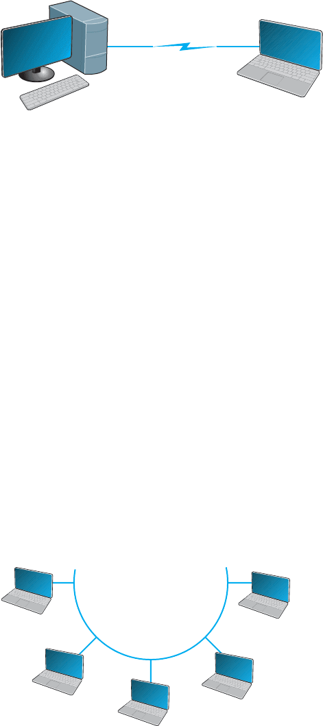
Figure 3.1 illustrates a point-to-point circuit, which is so named because it goes
from one point to another (e.g., one computer to another computer). These circuits some-
times are called dedicated circuits because they are dedicated to the use of these two
computers. This type of configuration is used when the computers generate enough data
to fill the capacity of the communication circuit. When an organization builds a network
using point-to-point circuits, each computer has its own circuit running from itself to
80 CHAPTER 3 PHYSICAL LAYER
Server
Client
computer
Circuit
FIGURE 3.1
Point-to-point circuit
the other computers. This can get very expensive, particularly if there is some distance
between the computers.
Figure 3.2 shows a multipoint circuit (also called a shared circuit). In this config-
uration, many computers are connected on the same circuit. This means that each must
share the circuit with the others. The disadvantage is that only one computer can use the
circuit at a time. When one computer is sending or receiving data, all others must wait.
The advantage of multipoint circuits is that they reduce the amount of cable required and
typically use the available communication circuit more efficiently. Imagine the number
of circuits that would be required if the network in Figure 3.2 was designed with sep-
arate point-to-point circuits. For this reason, multipoint configurations are cheaper than
point-to-point circuits. Thus, multipoint circuits typically are used when each computer
does not need to continuously use the entire capacity of the circuit or when building
point-to-point circuits is too expensive. Wireless circuits are almost always multipoint
circuits because multiple computers use the same radio frequencies and must take turns
transmitting.
3.2.2 Data Flow
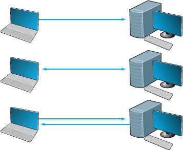
Circuits can be designed to permit data to flow in one direction or in both directions. Actu-
ally, there are three ways to transmit: simplex, half-duplex, and full-duplex (Figure 3.3).
Simplex transmission is one-way transmission, such as that with radios and TVs.
Half-duplex transmission is two-way transmission, but you can transmit in only
one direction at a time. A half-duplex communication link is similar to a walkie-talkie
link; only one computer can transmit at a time. Computers use control signals to negotiate
Client
computer
Client
computer
Client
computer
Client
computer
Server
FIGURE 3.2 Multipoint
circuit
3.2 CIRCUITS 81
Client
computer
Server
Simplex
Half-duplex
Full-duplex
FIGURE 3.3 Simplex, half-duplex,
and full-duplex transmissions
which will send and which will receive data. The amount of time half-duplex commu-
nication takes to switch between sending and receiving is called turnaround time (also
called retrain time or reclocking time). The turnaround time for a specific circuit can
be obtained from its technical specifications (often between 20 and 50 milliseconds).
Europeans sometimes use the term simplex circuit to mean a half-duplex circuit.
With full-duplex transmission, you can transmit in both directions simultaneously,
with no turnaround time.
How do you choose which data flow method to use? Obviously, one factor is the
application. If data always need to flow only in one direction (e.g., from a remote sensor
to a host computer), then simplex is probably the best choice. In most cases, however,
data must flow in both directions.
The initial temptation is to presume that a full-duplex channel is best; however,
each circuit has only so much capacity to carry data. Creating a full-duplex circuit means
that the available capacity in the circuit is divided—half in one direction and half in the
other. In some cases, it makes more sense to build a s et of simplex circuits in the same
way a set of one-way streets can increase the speed of traffic. In other cases, a half-duplex
circuit may work best. For example, terminals connected to mainframes often transmit
data to the host, wait for a reply, transmit more data, and so on, in a turn-taking process;
usually, traffic does not need to flow in both directions simultaneously. Such a traffic
pattern is ideally suited to half-duplex circuits.
3.2.3 Multiplexing
Multiplexing means to break one high-speed physical communication circuit into several
lower-speed logical circuits so that many different devices can simultaneously use it but
still “think” that they have their own separate circuits (the multiplexer is “transparent”). It
is multiplexing (specifically, wavelength division multiplexing [WDM], discussed later
in this section) that has enabled the almost unbelievable growth in network capacity
discussed in Chapter 1; without WDM, the Internet would have collapsed in the 1990s.
Multiplexing often is done in multiples of 4 (e.g., 8, 16). Figure 3.4 shows a
four-level multiplexed circuit. Note that two multiplexers are needed for each circuit:
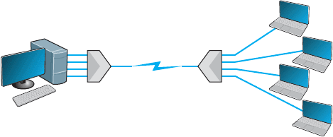
82 CHAPTER 3 PHYSICAL LAYER
Server
Circuit
Four client
computers
Four-level
multiplexer
Four-level
multiplexer
FIGURE 3.4
Multiplexed circuit
one to combine the four original circuits into the one multiplexed circuit and one to
separate them back into the four separate circuits.
The primary benefit of multiplexing is to save money by reducing the amount of
cable or the number of network circuits that must be installed. For example, if we did not
use multiplexers in Figure 3.4, we would need to run four separate circuits from the clients
to the server. If the clients were located close to the server, this would be inexpensive.
However, if they were located several miles away, the extra costs could be substantial.
There are four types of multiplexing: frequency division multiplexing (FDM), time
division multiplexing (TDM), statistical time division multiplexing (STDM), and wave-
length division multiplexing WDM.
Frequency Division Multiplexing Frequency division multiplexing (FDM) can be
described as dividing the circuit “horizontally” so that many signals can travel a single
communication circuit simultaneously. The circuit is divided into a series of separate
channels, each transmitting on a different frequency, much like series of different radio
or TV stations. All signals exist in the media at the same time, but because they are on
different frequencies, they do not interfere with each other.
Figure 3.5 illustrates the use of FDM to divide one circuit into four channels. Each
channel is a separate logical circuit, and the devices connected to them are unaware that
their circuit is multiplexed. In the same way that radio stations must be assigned separate
frequencies to prevent interference, so must the signals in a FDM circuit. The guardbands
in Figure 3.5 are the unused portions of the circuit that separate these frequencies from
each other.
With FDM, the total capacity of the physical circuit is simply divided among the
multiplexed circuits. For example, suppose we had a physical circuit with a data rate of
64 Kbps that we wanted to divide into four circuits. We would simply divide the 64 Kbps
among the four circuits and assign each circuit 16 Kbps. However, because FDM needs
guardbands, we also have to allocate some of the capacity to the guardbands, so we might
actually end up with four circuits, each providing 15 Kbps, with the remaining 4 Kbps
allocated to the guardbands. There is no requirement that all circuits be the same size,
as you will see in a later section. FDM was commonly used in older telephone systems,
which is why the bandwidth on older phone systems was only 3,000 Hz, not the 4,000 Hz
actually available—1,000 Hz were used as guardbands, with the voice signals traveling
between two guardbands on the outside of the channel.
3.2 CIRCUITS 83
Server
Circuit
Four client
computers
FDM
3000 hertz available
bandwidth
FDM
Guardband
2600-1
2200-0
Guardband
2000-1
1600-0
Guardband
1400-1
1000-0
Guardband
800-1
400-0
Guardband
FIGURE 3.5 Frequency division
multiplex (FDM) circuit
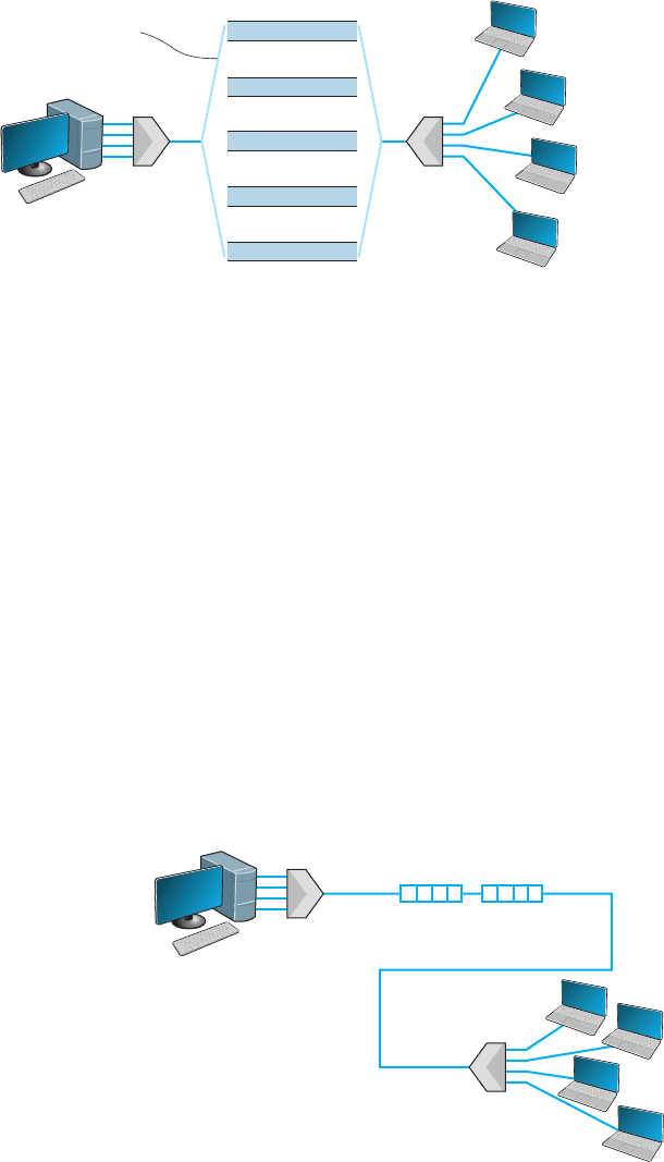
Time Division Multiplexing Time division multiplexing (TDM) shares a commu-
nication circuit among two or more computers by having them take turns, dividing the
circuit vertically, so to speak. Figure 3.6 shows the same four computers connected using
TDM. In this case, one character is taken from each computer in turn, transmitted down
the circuit, and delivered to the appropriate device at the far end (e.g., one character from
computer A, then one from B, one from C, one from D, another from A, another from
B, and so on). Time on the circuit is allocated even when data are not being transmitted,
so that some capacity is wasted when terminals are idle. TDM generally is more efficient
than FDM because it does not need guardbands. Guardbands use “space” on the circuit
that otherwise could be used to transmit data. Therefore, if one divides a 64-Kbps circuit
into four circuits, the result would be four 16-Kbps circuits.
Statistical Time Division Multiplexing Statistical time division multiplexing
(STDM) is the exception to the rule that the capacity of the multiplexed circuit must
equal the sum of the circuits it combines. STDM allows more terminals or computers
Server
FDM
FDM
Circuit
Four
client computers
DCBA DCBA
FIGURE 3.6 Time
division multiplex (TDM)
circuit
84 CHAPTER 3 PHYSICAL LAYER
to be connected to a circuit than does FDM or TDM. If you have four computers
connected to a multiplexer and each can transmit at 64 Kbps, then you should have a
circuit capable of transmitting 256 Kbps (4 × 64 Kbps). However, not all computers
will be transmitting continuously at their maximum transmission speed. Users typically
pause to read their screens or spend time typing at lower speeds. Therefore, you do not
need to provide a speed of 256 Kbps on this multiplexed circuit. If you assume that
only two computers will ever transmit at the same time, 128 Kbps would be enough.
STDM is called statistical because selection of transmission speed for the multiplexed
circuit is based on a statistical analysis of the usage requirements of the circuits to be
multiplexed.
The key benefit of STDM is that it provides more efficient use of the circuit
and saves money. You can buy a lower-speed, less-expensive circuit than you could
using FDM or TDM. STDM introduces two additional complexities. First, STDM can
cause time delays. If all devices start transmitting or receiving at the same time (or
just more than at the statistical assumptions), the multiplexed circuit cannot transmit
all the data it receives because it does not have sufficient capacity. Therefore, STDM
must have internal memory to store the incoming data that it cannot immediately trans-
mit. When traffic is particularly heavy, you may have a 1- to 30-second delay. The
second problem is that because the logical circuits are not permanently assigned to
specific devices as they are in FDM and TDM, the data from one device are inter-
spersed with data from other devices. The first message might be from the third com-
puter, the second from the first computer, and so on. Therefore, we need to add some
address information to each packet to make sure we can identify the logical circuit to
which it belongs. This is not a major problem, but it does increase the complexity of
the multiplexer and also slightly decreases efficiency, because now we must “waste”
some of the circuit’s capacity in transmitting the extra address we have added to each
packet.
Wavelength Division Multiplexing Wavelength division multiplexing (WDM) is a
version of FDM used in fiber-optic cables. When fiber-optic cables were first developed,
the devices attached to them were designed to use only one color of light generated by
a laser or LED. With one commonly used type of fiber cable, the data rate is 622 Mbps
(622 million bits per second). At first, the 622-Mbps data rate seemed wonderful. Then
the amount of data transferred over the Internet began doubling at fairly regular intervals,
and several companies began investigating how we could increase the amount of data
sent over existing fiber-optic cables.
The answer, in hindsight, was obvious. Light has different frequencies (i.e., colors),
so rather than building devices to transmit using only one color, why not send multiple
signals, each in a different frequency, through the same fiber cable? By simply attaching
different devices that could transmit in the full spectrum of light rather than just one
frequency, the capacity of the existing fiber-optic cables could be dramatically increased,
with no change to the physical cables themselves.
Wavelength division multiplexing works by using lasers to transmit different fre-
quencies of light (i.e., colors) through the same fiber-optic cable. As with FDM, each
logical circuit is assigned a different frequency, and the devices attached to the circuit
don’t “know” they are multiplexed over the same physical circuit.