Fitzgerald A.E. Electric Machinery
Подождите немного. Документ загружается.

456 CHAPTER 9 Single- and Two-Phase Motors
i
Auxiliary
winding
(a)
~iaux
X'q,,
,9
400
300
~D
200
~D
~, 100
0
0
i I i
iiiiii i i[i.i...l
i
Main and
i
[ auxiliary
,fwin
..... Main winding,
i only ~.~-'
20 40 60 80
Percent synchronous speed
I
yl ;!-"
.............. !
";a'" ............... ~ i"cl
........
lOO
(b) (c)
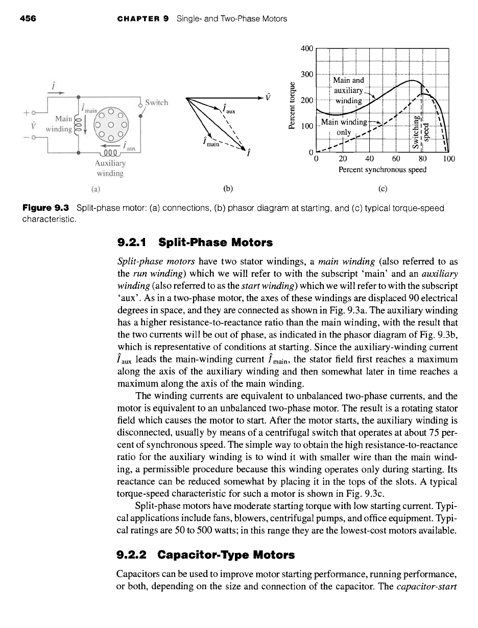
Figure 9.3
Split-phase motor: (a) connections, (b) phasor diagram at starting, and (c) typical torque-speed
characteristic.
9.2.1 Split.Phase Motors
Split-phase motors
have two stator windings, a
main winding
(also referred to as
the
run winding)
which we will refer to with the subscript 'main' and an
auxiliary
winding
(also referred to as the
start winding)
which we will refer to with the subscript
'aux'. As in a two-phase motor, the axes of these windings are displaced 90 electrical
degrees in space, and they are connected as shown in Fig. 9.3a. The auxiliary winding
has a higher resistance-to-reactance ratio than the main winding, with the result that
the two currents will be out of phase, as indicated in the phasor diagram of Fig. 9.3b,
which is representative of conditions at starting. Since the auxiliary-winding current
iaux leads the main-winding
current
Imain, the stator field first reaches a maximum
along the axis of the auxiliary winding and then somewhat later in time reaches a
maximum along the axis of the main winding.
The winding currents are equivalent to unbalanced two-phase currents, and the
motor is equivalent to an unbalanced two-phase motor. The result is a rotating stator
field which causes the motor to start. After the motor starts, the auxiliary winding is
disconnected, usually by means of a centrifugal switch that operates at about 75 per-
cent of synchronous speed. The simple way to obtain the high resistance-to-reactance
ratio for the auxiliary winding is to wind it with smaller wire than the main wind-
ing, a permissible procedure because this winding operates only during starting. Its
reactance can be reduced somewhat by placing it in the tops of the slots. A typical
torque-speed characteristic for such a motor is shown in Fig. 9.3c.
Split-phase motors have moderate starting torque with low starting current. Typi-
cal applications include fans, blowers, centrifugal pumps, and office equipment. Typi-
cal ratings are 50 to 500 watts; in this range they are the lowest-cost motors available.
9.2.2 Capacitor.Type Motors
Capacitors can be used to improve motor starting performance, running performance,
or both, depending on the size and connection of the capacitor. The
capacitor-start
9,2 Starting and Running Performance of Single-Phase Induction and Synchronous Motors 457
I
Switch
+ o , a
Main ~~
1~" winding C
-° T
Iaux
Auxiliary
winding
I
aux
Imain
400
= 300
©
=
200
(1,)
100
0
0
[ i
---~ auxiliary
Main winding---),'"
~]
- only l;" ........... ~[ : ......... i i-~ - ........
20 40 60 80 100
Percent synchronous speed
(a) (b) (c)
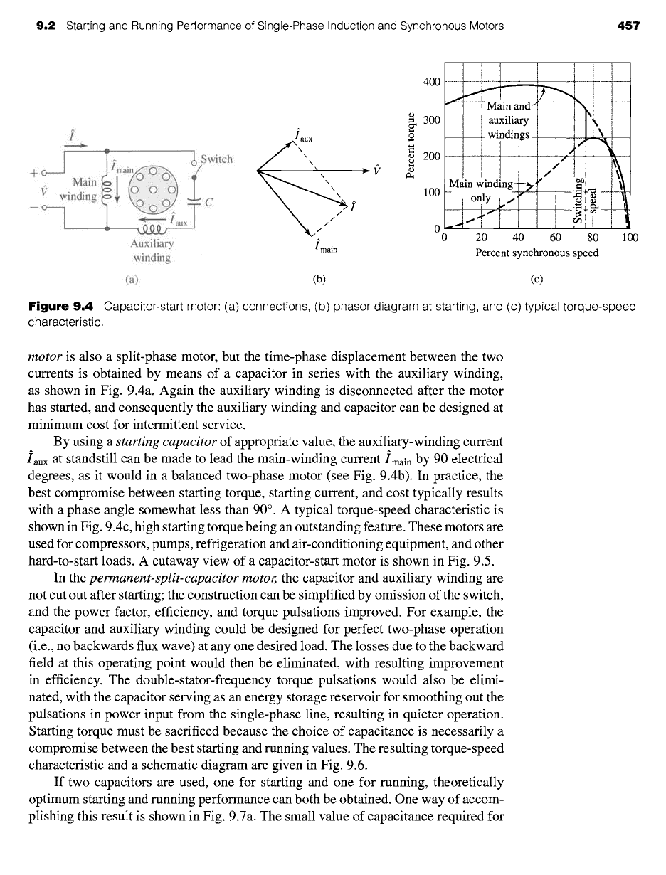
Figure 9.4
Capacitor-start motor: (a) connections, (b) phasor diagram at starting, and (c) typical torque-speed
characteristic.
motor is also a split-phase motor, but the time-phase displacement between the two
currents is obtained by means of a capacitor in series with the auxiliary winding,
as shown in Fig. 9.4a. Again the auxiliary winding is disconnected after the motor
has started, and consequently the auxiliary winding and capacitor can be designed at
minimum cost for intermittent service.
By using a
starting capacitor of appropriate value, the auxiliary-winding current
iaux at standstill can be made to lead the main-winding
current Imain
by 90 electrical
degrees, as it would in a balanced two-phase motor (see Fig. 9.4b). In practice, the
best compromise between starting torque, starting current, and cost typically results
with a phase angle somewhat less than 90 °. A typical torque-speed characteristic is
shown in Fig. 9.4c, high starting torque being an outstanding feature. These motors are
used for compressors, pumps, refrigeration and air-conditioning equipment, and other
hard-to-start loads. A cutaway view of a capacitor-start motor is shown in Fig. 9.5.
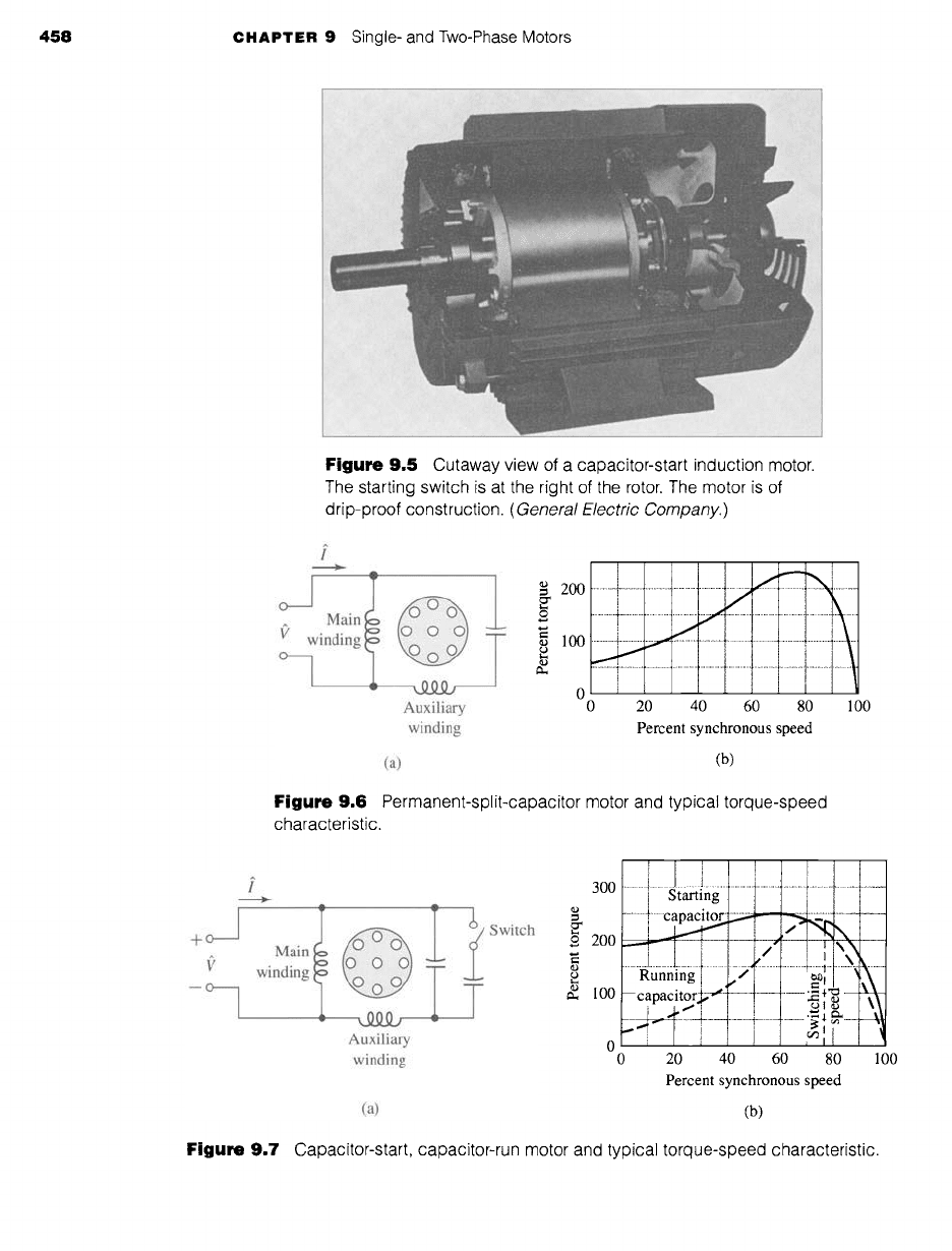
In the
permanent-split-capacitor motor, the capacitor and auxiliary winding are
not cut out after starting; the construction can be simplified by omission of the switch,
and the power factor, efficiency, and torque pulsations improved. For example, the
capacitor and auxiliary winding could be designed for perfect two-phase operation
(i.e., no backwards flux wave) at any one desired load. The losses due to the backward
field at this operating point would then be eliminated, with resulting improvement
in efficiency. The double-stator-frequency torque pulsations would also be elimi-
nated, with the capacitor serving as an energy storage reservoir for smoothing out the
pulsations in power input from the single-phase line, resulting in quieter operation.
Starting torque must be sacrificed because the choice of capacitance is necessarily a
compromise between the best starting and running values. The resulting torque-speed
characteristic and a schematic diagram are given in Fig. 9.6.
If two capacitors are used, one for starting and one for running, theoretically
optimum starting and running performance can both be obtained. One way of accom-
plishing this result is shown in Fig. 9.7a. The small value of capacitance required for
458 CHAPTER 9 Single- and Two-Phase Motors
Figure 9.5 Cutaway view of a capacitor-start induction motor.
The starting switch is at the right of the rotor. The motor is of
drip-proof construction.
(General Electric Company.)
i
• "- A
I _L ~20o
Main o
winding T ~= 100
/
" 0
Auxiliary 0
winding
!
20 40 60 80 100
Percent synchronous speed
(a) (b)
Figure 9.6 Permanent-split-capacitor motor and typical torque-speed
characteristic.
+O
--O
i
Main
winding
I _ T
Auxiliary
winding
Switch
300
£ 200
~, 100
0
0
I
J I
Starting
............................... 1 ............................................ '......,...:
..~
Running
-- capacitor~'~ -~ ~
20 40 60 80 100
Percent synchronous speed
(a) (b)
Figure 9.7 Capacitor-start, capacitor-run motor and typical torque-speed characteristic.
9.2
Starting and Running Performance of Single-Phase Induction and Synchronous Motors
459
optimum running conditions is permanently connected in series with the auxiliary
winding, and the much larger value required for starting is obtained by a capacitor
connected in parallel with the running capacitor via a switch with opens as the motor
comes up to speed. Such a motor is known as a
capacitor-start, capacitor-run motor.
The capacitor for a capacitor-start motor has a typical value of 300 #F for a
500-W motor. Since it must carry current for just the starting time, the capacitor is
a special compact ac electrolytic type made for motor-starting duty. The capacitor
for the same motor permanently connected has a typical rating of 40 #E and since it
operates continuously, the capacitor is an ac paper, foil, and oil type. The cost of the
various motor types is related to performance: the capacitor-start motor has the lowest
cost, the permanent-split-capacitor motor next, and the capacitor-start, capacitor-run
motor the highest cost.
A 2.5-kW 120-V 60-Hz capacitor-start motor has the following impedances for the main and
auxiliary windings (at starting):
Zmain ---
4.5 + j3.7 f2 main winding
Zaux -- 9.5 + j 3.5 f2 auxiliary winding
Find the value of starting capacitance that will place the main and auxiliary winding
currents in quadrature at starting.
II Solution
The
currents l[main
and irau x are shown in Fig. 9.4a and b. The impedance angle of the main
winding is
~main =
tan -1 ~ = 39.6 °
To produce currents in time quadrature with the main winding, the impedance angle of the
auxiliary winding circuit (including the starting capacitor) must be
4) = 39.6 ° - 90.0 ° = -50.4 °
The combined impedance of the auxiliary winding and starting capacitor is equal to
Ztotal
=
Zaux
+ j Xc = 9.5 + j (3.5 +
Xc) S2
1 is the reactance of the capacitor and co -- 2zr60 ~ 377 rad/sec. Thus
where Xc -- -;--d
tan-1 9.5 = -50"4°
3.5 + Xc
= tan (-50.4 °) = - 1.21
9.5
and hence
Xc -- -1.21 x 9.5 - 3.5 -- -15.0
EXAMPLE 9.1
460 CHAPTER 9 Single- and Two-Phase Motors
The capacitance C is then
-1 -1
C = = = 177/zF
coXc 377 x (-15.0)
~ractice Problem 9.
Consider the motor of Example 9.1. Find the phase angle between the main- and auxiliary-
winding currents if the 177-/xF capacitor is replaced by a 200-/~F capacitor.
Solution
85.2 °
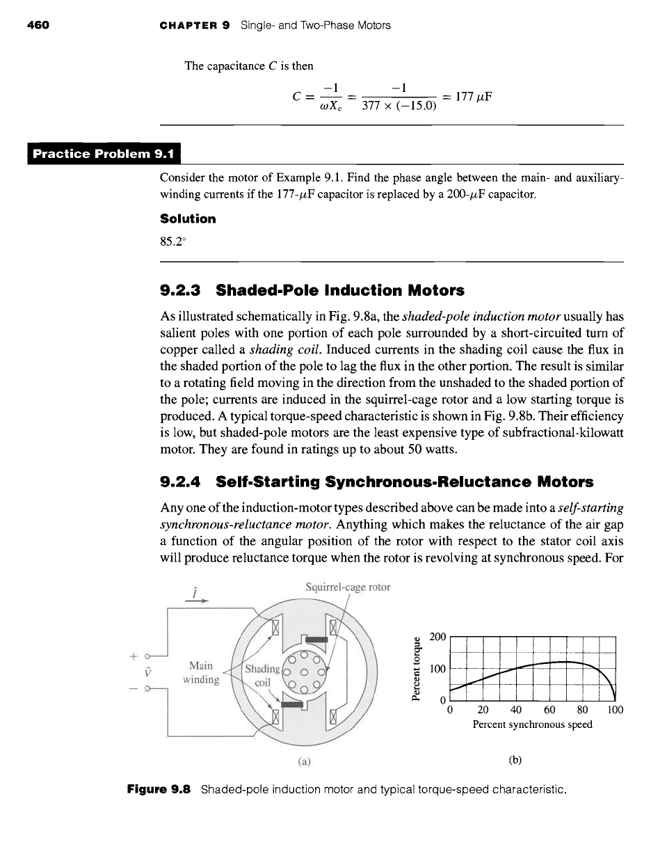
9.2.3 Shaded.Pole Induction Motors
As illustrated schematically in Fig. 9.8a, the
shaded-pole induction motor
usually has
salient poles with one portion of each pole surrounded by a short-circuited turn of
copper called a
shading coil.
Induced currents in the shading coil cause the flux in
the shaded portion of the pole to lag the flux in the other portion. The result is similar
to a rotating field moving in the direction from the unshaded to the shaded portion of
the pole; currents are induced in the squirrel-cage rotor and a low starting torque is
produced. A typical torque-speed characteristic is shown in Fig. 9.8b. Their efficiency
is low, but shaded-pole motors are the least expensive type of subfractional-kilowatt
motor. They are found in ratings up to about 50 watts.
9.2.4 Self-Starting Synchronous-Reluctance Motors
Any one of the induction-motor types described above can be made into a
self-starting
synchronous-reluctance motor.
Anything which makes the reluctance of the air gap
a function of the angular position of the rotor with respect to the stator coil axis
will produce reluctance torque when the rotor is revolving at synchronous speed. For
-k- o
B o
i Squirrel-cage rotor
>
Main
win
200
.................................................................................................................
lOO ~~~~ ~\
~- 0 1 i
0 20 40 60 80 100
Percent synchronous speed
(a) (b)
Figure 9.8
Shaded-pole induction motor and typical torque-speed characteristic.
9,2 Starting and Running Performance of Single-Phase Induction and Synchronous Motors 461
600
500
4O0
~D
=
©
300
200
100
.................. i .................. Main~ ............................................................................... and ............ _¢_/~. \~ .................................. ................
__ auxiliary_._
Z~al~,~i
I ~ winding/~ /~- l i ~X i \[
I
I- ~ ............. [ ...... .~l~,t ...................................... ]~ ...........
~)~ain :indi!g +~'---~
.......... oq,y ....... l ................ l, ........... T .................................
0 20 40 60 80 100
Percent synchronous speed
(a) (b)
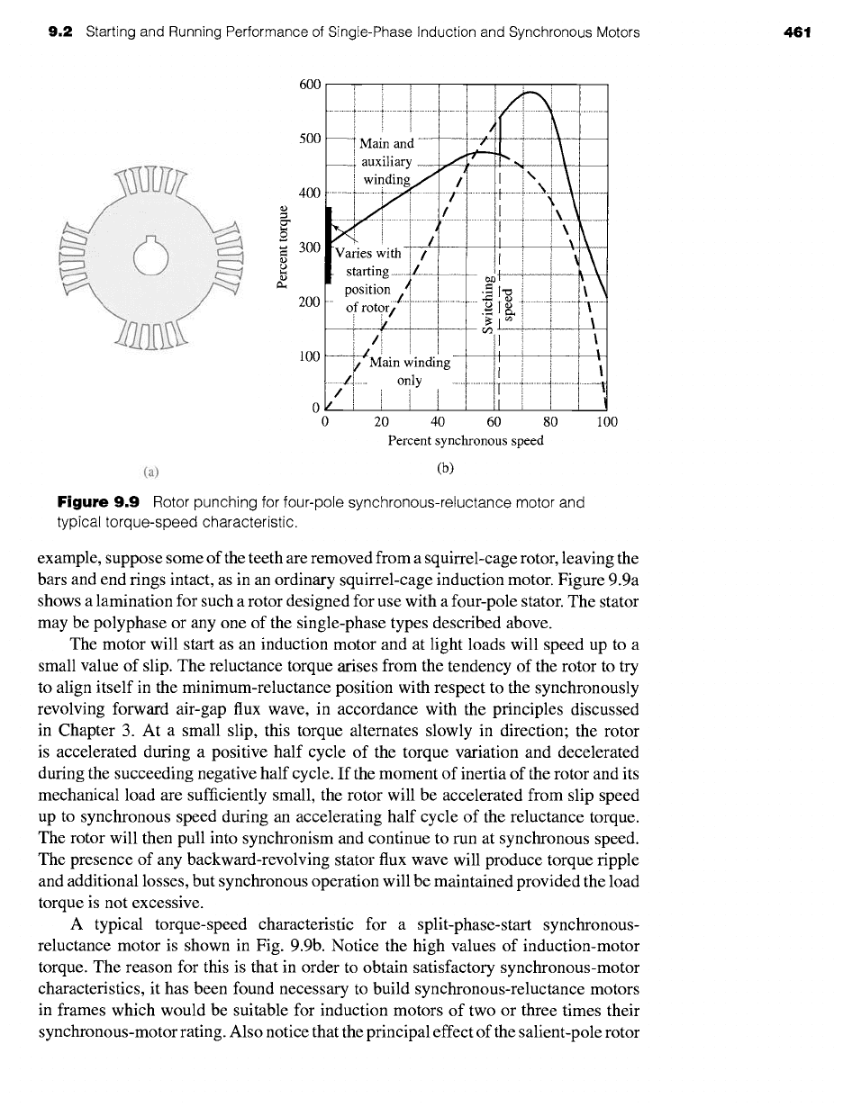
Figure
9.9 Rotor punching for four-pole synchronous-reluctance motor and
typical torque-speed characteristic.
example, suppose some of the teeth are removed from a squirrel-cage rotor, leaving the
bars and end tings intact, as in an ordinary squirrel-cage induction motor. Figure 9.9a
shows a lamination for such a rotor designed for use with a four-pole stator. The stator
may be polyphase or any one of the single-phase types described above.
The motor will start as an induction motor and at light loads will speed up to a
small value of slip. The reluctance torque arises from the tendency of the rotor to try
to align itself in the minimum-reluctance position with respect to the synchronously
revolving forward air-gap flux wave, in accordance with the principles discussed
in Chapter 3. At a small slip, this torque alternates slowly in direction; the rotor
is accelerated during a positive half cycle of the torque variation and decelerated
during the succeeding negative half cycle. If the moment of inertia of the rotor and its
mechanical load are sufficiently small, the rotor will be accelerated from slip speed
up to synchronous speed during an accelerating half cycle of the reluctance torque.
The rotor will then pull into synchronism and continue to run at synchronous speed.
The presence of any backward-revolving stator flux wave will produce torque ripple
and additional losses, but synchronous operation will be maintained provided the load
torque is not excessive.
A typical torque-speed characteristic for a split-phase-start synchronous-
reluctance motor is shown in Fig. 9.9b. Notice the high values of induction-motor
torque. The reason for this is that in order to obtain satisfactory synchronous-motor
characteristics, it has been found necessary to build synchronous-reluctance motors
in frames which would be suitable for induction motors of two or three times their
synchronous-motor rating. Also notice that the principal effect of the salient-pole rotor
462
CHAPTER 9 Single- and Two-Phase Motors
on the induction-motor characteristic is at standstill, where considerable "cogging"
is evident; i.e., the torque varies considerably with rotor position.
9.2.5 Hysteresis Motors
The phenomenon of hysteresis can be used to produce mechanical torque. In its
simplest form, the rotor of a
hysteresis motor
is a smooth cylinder of magnetically
hard steel, without windings or teeth. It is placed inside a slotted stator carrying
distributed windings designed to produce as nearly as possible a sinusoidal space
distribution of flux, since undulations in the flux wave greatly increase the losses. In
single-phase motors, the stator windings usually are of the permanent-split-capacitor
type, as in Fig. 9.6. The capacitor is chosen so as to result in approximately balanced
two-phase conditions within the motor windings. The stator then produces a primarily
space-fundamental air-gap field revolving at synchronous speed.
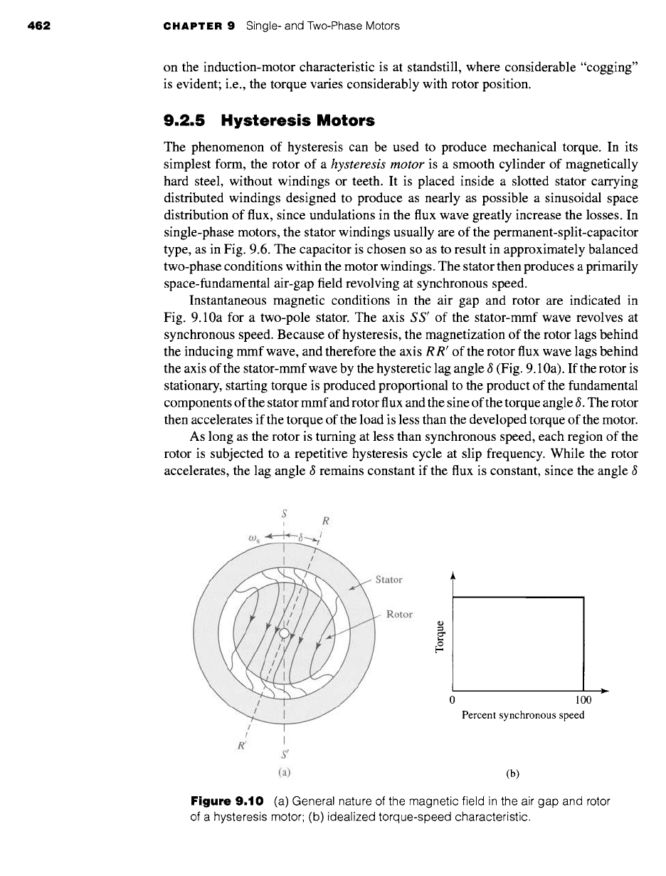
Instantaneous magnetic conditions in the air gap and rotor are indicated in
Fig. 9.10a for a two-pole stator. The axis
S S'
of the stator-mmf wave revolves at
synchronous speed. Because of hysteresis, the magnetization of the rotor lags behind
the inducing mmf wave, and therefore the axis R R' of the rotor flux wave lags behind
the axis of the stator-mmf wave by the hysteretic lag angle 6 (Fig. 9.10a). If the rotor is
stationary, starting torque is produced proportional to the product of the fundamental
components of the stator mmf and rotor flux and the sine of the torque angle 6. The rotor
then accelerates if the torque of the load is less than the developed torque of the motor.
As long as the rotor is turning at less than synchronous speed, each region of the
rotor is subjected to a repetitive hysteresis cycle at slip frequency. While the rotor
accelerates, the lag angle 6 remains constant if the flux is constant, since the angle 6
S
R
tator
Rotor
~D
¢
/
R f
I
S'
(a)
0 1 O0
Percent synchronous speed
(b)
Figure
9.10 (a) General nature of the magnetic field in the air gap and rotor
of a hysteresis motor; (b) idealized torque-speed characteristic.
9.3 Revolving-Field Theory of Single-Phase Induction Motors 463
depends merely on the hysteresis loop of the rotor material and is independent of
the rate at which the loop is traversed. The motor therefore develops constant torque
right up to synchronous speed, as shown in the idealized torque-speed characteristic
of Fig. 9.10b. This feature is one of the advantages of the hysteresis motor. In con-
trast with a reluctance motor, which must "snap" its load into synchronism from an
induction-motor torque-speed characteristic, a hysteresis motor can synchronize any
load which it can accelerate, no matter how great the inertia. After reaching synchro-
nism, the motor continues to run at synchronous speed and adjusts its torque angle so
as to develop the torque required by the load.
The hysteresis motor is inherently quiet and produces smooth rotation of its load.
Furthermore, the rotor takes on the same number of poles as the stator field. The
motor lends itself to multispeed synchronous operation when the stator is wound with
several sets of windings and utilizes pole-changing connections. The hysteresis motor
can accelerate and synchronize high-inertia loads because its torque is uniform from
standstill to synchronous speed.
9.3 REVOLVING-FIELD THEORY OF
SINGLE-PHASE INDUCTION MOTORS
As discussed in Section 9.1, the stator-mmf wave of a single-phase induction motor
can be shown to be equivalent to two constant-amplitude mmf waves revolving at
synchronous speed in opposite directions. Each of these component stator-mmf waves
induces its own component rotor currents and produces induction-motor action just
as in a balanced polyphase motor. This double-revolving-field concept not only is
useful for qualitative visualization but also can be developed into a quantitative theory
applicable to a wide variety of induction-motor types. We will not discuss the full
quantitative theory here. 1 However, we will consider the simpler, but important case
of a single-phase induction motor running on only its main winding.
Consider conditions with the rotor stationary and only the main stator wind-
ing excited. The motor then is equivalent to a transformer with its secondary short-
circuited. The equivalent circuit is shown in Fig. 9.11 a, where Rl,main and X
1,main
are,
respectively, the resistance and leakage reactance of the main winding,
Xm,main
is the
magnetizing reactance, and
R2,main
and
X2,main are
the standstill values of the rotor
resistance and leakage reactance referred to the main stator winding by use of the
appropriate turns ratio. Core loss, which is omitted here, will be accounted for later
as if it were a rotational loss. The applied voltage is f', and the main-winding current
is
l~main. The voltage
J~main
is the counter emf generated in the main winding by the
stationary pulsating air-gap flux wave produced by the combined action of the stator
and rotor currents.
In accordance with the double-revolving-field concept of Section 9.1, the stator
mmf can be resolved into half-amplitude forward and backward rotating fields. At
1
For an extensive treatment of single-phase motors, see, for example, C. B. Veinott,
Fractional- and
Subfractional-Horsepower Electric Motors,
McGraw-Hill, New York, 1970.
464 CHAPTER 9 Single- and Two-Phase Motors
gl,main Xl,main X2
--i main E~ain ~ R2
(a)
gl,main Xl,main 0.5 X 2
+ 'fi 0. , 0.5 R 2
^ ~
V
_ +-t
~.5
UX~,ma~ 0.5
/~m_aaii,b R2
Rl,main Xl,main 0.5 X 2
i
I 0.5 Zf 0. _.
+!
V .
Emain,b, 0.5 R 2
0.5 ib ~--s
(b) (c)
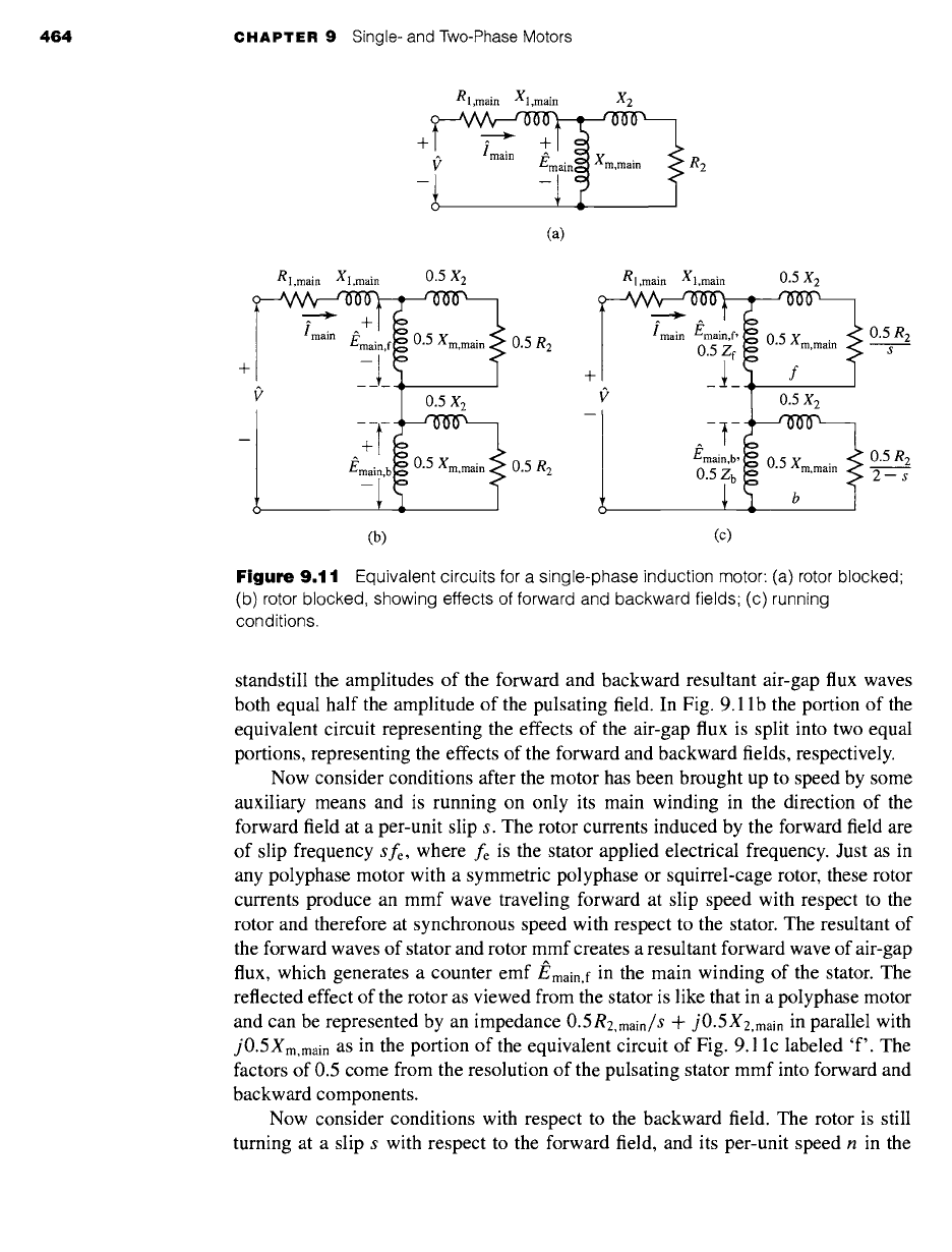
Figure
9.11 Equivalent circuits for a single-phase induction motor: (a) rotor blocked
(b) rotor blocked, showing effects of forward and backward fields; (c) running
conditions.
standstill the amplitudes of the forward and backward resultant air-gap flux waves
both equal half the amplitude of the pulsating field. In Fig. 9.11 b the portion of the
equivalent circuit representing the effects of the air-gap flux is split into two equal
portions, representing the effects of the forward and backward fields, respectively.
Now consider conditions after the motor has been brought up to speed by some
auxiliary means and is running on only its main winding in the direction of the
forward field at a per-unit slip s. The rotor currents induced by the forward field are
of slip frequency
sfe,
where fe is the stator applied electrical frequency. Just as in
any polyphase motor with a symmetric polyphase or squirrel-cage rotor, these rotor
currents produce an mmf wave traveling forward at slip speed with respect to the
rotor and therefore at synchronous speed with respect to the stator. The resultant of
the forward waves of stator and rotor mmf creates a resultant forward wave of air-gap
flux, which generates a counter
emf
J~main,f in the main winding of the stator. The
reflected effect of the rotor as viewed from the stator is like that in a polyphase motor
and can be represented by an impedance
0.5R2,main/S Jr
j0.5X2,main
in parallel with
j0.5Xm,main as
in the portion of the equivalent circuit of Fig. 9.1 lc labeled 'f'. The
factors of 0.5 come from the resolution of the pulsating stator mmf into forward and
backward components.
Now consider conditions with respect to the backward field. The rotor is still
turning at a slip s with respect to the forward field, and its per-unit speed n in the
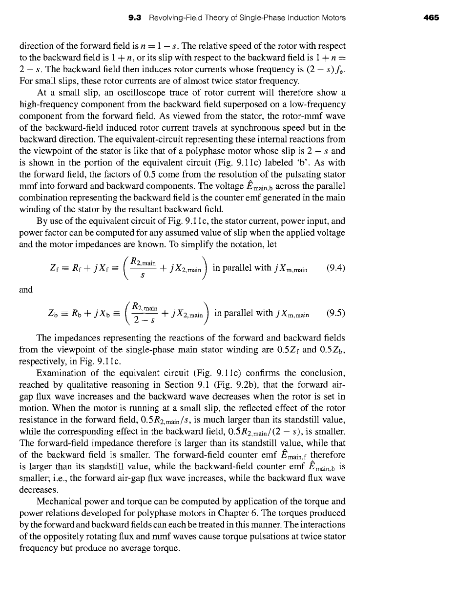
9,3 Revolving-Field Theory of Single-Phase Induction Motors 465
direction of the forward field is n = 1 - s. The relative speed of the rotor with respect
to the backward field is 1 + n, or its slip with respect to the backward field is 1 + n =
2 - s. The backward field then induces rotor currents whose frequency is (2 - s)fe-
For small slips, these rotor currents are of almost twice stator frequency.
At a small slip, an oscilloscope trace of rotor current will therefore show a
high-frequency component from the backward field superposed on a low-frequency
component from the forward field. As viewed from the stator, the rotor-mmf wave
of the backward-field induced rotor current travels at synchronous speed but in the
backward direction. The equivalent-circuit representing these internal reactions from
the viewpoint of the stator is like that of a polyphase motor whose slip is 2 - s and
is shown in the portion of the equivalent circuit (Fig. 9.11c) labeled 'b'. As with
the forward field, the factors of 0.5 come from the resolution of the pulsating stator
mmf into forward and backward components. The voltage
J~main,b across
the parallel
combination representing the backward field is the counter emf generated in the main
winding of the stator by the resultant backward field.
By use of the equivalent circuit of Fig. 9.11 c, the stator current, power input, and
power factor can be computed for any assumed value of slip when the applied voltage
and the motor impedances are known. To simplify the notation, let
( R2,main )
Zf ~ Rf -I-
jXf = ~ -F jX2,main in parallel with j Xm,main (9.4)
s
and
R2,main )
Zb = Rb + jXb = ~ + jX2,main in parallel with jXm, main
(9.5)
The impedances representing the reactions of the forward and backward fields
from the viewpoint of the single-phase main stator winding are 0.5Zf and 0.5Zb,
respectively, in Fig. 9.11 c.
Examination of the equivalent circuit (Fig. 9.11c) confirms the conclusion,
reached by qualitative reasoning in Section 9.1 (Fig. 9.2b), that the forward air-
gap flux wave increases and the backward wave decreases when the rotor is set in
motion. When the motor is running at a small slip, the reflected effect of the rotor
resistance in the forward field, 0.5
R2,main/S,
is much larger than its standstill value,
while the corresponding effect in the backward field,
0.5R2,main/(2 - s),
is smaller.
The forward-field impedance therefore is larger than its standstill value, while that
of the backward field is smaller. The forward-field counter
emf
Emain, f therefore
is larger than its standstill value, while the backward-field counter
emf
/~main,b is
smaller; i.e., the forward air-gap flux wave increases, while the backward flux wave
decreases.
Mechanical power and torque can be computed by application of the torque and
power relations developed for polyphase motors in Chapter 6. The torques produced
by the forward and backward fields can each be treated in this manner. The interactions
of the oppositely rotating flux and mmf waves cause torque pulsations at twice stator
frequency but produce no average torque.