Fabien B. Analytical System Dynamics: Modeling and Simulation
Подождите немного. Документ загружается.

288 6 Dynamic System Analysis and Simulation
b=0.75;
Phi = zeros(2,1);
Phi(1,1) = yp(1)-y(2);
Phi(2,1) = m*yp(2) + b*y(2) + k*y(1);
return;
% end file: ex2_ide.m
%
% file: ex2_jacobian.m
%
function [J,M] = ex2_jacobian(y,yp,t)
m=0.3;
k=45.0;
b=0.75;
M = zeros(2,2);
J = zeros(2,2);
M(1,1) = 1;
M(2,2) = m;
J(1,2) = -1;
J(2,1) = k;
J(2,2) = b;
return;
% end file: ex2_jacobian.m
%
% file: ex2.m
%
clear all
m=0.3;
k=45.0;
b=0.75;
tspan = linspace(0,3,100)’;
y0 = [1.0e-2;0];
yp0 = [y0(2);-k*y0(1)/m];
[T,Y] = ride(’ex2_ide’,’ex2_jacobian’,tspan,y0,yp0);
% end file: ex2.m
The differential equation (b) can be written as
¨y
1
+ 2ζω ˙y
1
+ ω
2
y
1
= 0,
6.2 System Simulation 289
where ω
2
= k/m, ζ = (b/m)/(2ω), ω
2
d
= ω
2
n
(1 −ζ
2
). If ζ < 1 then, it can be
shown that the analytical solution to this differential equation is
y
1
(t) = y
1
(0)e
ζωt
cos ω
d
t +
ζ
p
1 − ζ
2
sin ω
d
t
!
+
˙y
1
(0)
ω
d
e
−ζωt
sin ω
d
t.
Recall that the condition ζ < 1 implies that the system response is ‘under-
damped’. If ζ = 1 then the system response is said to be ‘critically damped’.
If ζ > 1 the system response is said to be ‘overdamped’.
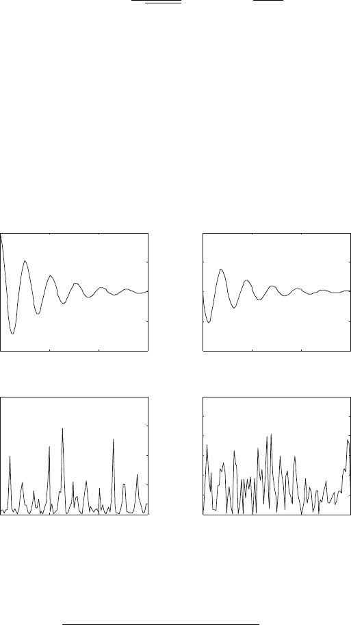
For the model parameters used here it can be seen that the system is
underdamped. The plots (i) and (ii) in Fig. 6.2 show the numerically com-
puted displacement and velocity of the system. The plots (iii) and (iv) in Fig.
6.2 show the absolute value of the error between the analytical solution and
the computed results. These figures indicate that the error in the numerical
solution is well below the specified error tolerance.
0 1 2 3
−0.01
−0.005
0
0.005
0.01
(i)
t
y
1
0 1 2 3
−0.2
−0.1
0
0.1
0.2
(ii)
t
y
2
0 1 2 3
0
2
4
6
8
x 10
−8
(iii)
t
|y
1
error|
0 1 2 3
0
0.5
1
1.5
2
2.5
3
x 10
−7
(iv)
t
|y
2
error|
Fig. 6.2 Example 6.12
290 6 Dynamic System Analysis and Simulation
Example 6.13.
θ
m
l
g
q
1
2
q
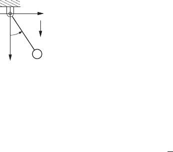
This example simulates the behavior of the simple pendu-
lum shown here using two different models of the system.
In the first model the angle θ is taken as the generalized
displacement. In the second model the variables q
1
and q
2
are used as the displacement coordinates for the system.
Using θ as the generalized displacement we can show that
Lagrange’s equation of motion is
ml
2
¨
θ + mgl sin θ = 0. (a)
If we define the state variables y
1
= θ and y
2
=
˙
θ then, (a) can be rewritten
as the implicit differential equations
0 = ˙y
1
− y
2
,
0 = ˙y
2
+
g
l
sin y
1
.
(b)
The parameters for this model are m = 0.25 kg, l = 0.3 m, and g = 9.8 m/s
2
.
The initial conditions are θ = y
1
= π/2 and
˙
θ = y
2
= 0.
The m-files required to simulate this version model are shown below.
%
% file: ex3a_ide.m
%
function Phi = ex3a_ide(y,yp,t)
m = 0.25;
L = 0.3;
g = 9.8;
Phi = zeros(2,1);
Phi(1,1) = yp(1) - y(2);
Phi(2,1) = yp(2) + (g/L)*sin(y(1));
return;
%
% file: ex3a_jacobian.m
%
function [J,M] = ex3a_jacobian(y,yp,t)
m = 0.25;
L = 0.3;
g = 9.8;
M = zeros(2,2);
J = zeros(2,2);
M(1,1) = 1;
M(2,2) = 1;
J(1,2) = -1;
J(2,1) = (g/L)*cos(y(1));
return;

6.2 System Simulation 291
%
% file ex3a.m
%
m = 0.25;
L = 0.3;
g = 9.8;
tspan = linspace(0,3,100)’;
y0 = [pi/2.0;0];
yp0 = [y0(1);-(g/L)*sin(y0(1))];
[T,Y] = ride(’ex3a_ide’,’ex3a_jacobian’,tspan,y0,yp0);
If we use q
1
and q
2
as the displacements, the Lagrange’s equations of
motion are
m¨q
1
+ 2λq
1
= 0,
m¨q
2
+ 2λq
2
− mg = 0,
q
2
1
+ q
2
2
− l
2
= 0.
(b)
The system (b) can be rewritten in state variable form using y
1
= q
1
, y
2
= q
2
,
y
3
= ˙q
1
, y
4
= ˙q
2
and y
5
= λ. This yields the index-3 DAEs
0 = ˙y
1
− y
3
,
0 = ˙y
2
− y
4
,
0 = m ˙y
3
+ 2y
5
y
1
,
0 = m ˙y
4
+ 2y
5
y
2
− mg,
0 = y
2
1
+ y
2
2
− l
2
.
(c)
Finally, we can put (c) in the GGL stabilized index-2 form (see Section 5.3.3).
This is accomplished by adding the multiplier y
6
and adjoining the the deriva-
tive of the displacement constraint to get
0 = ˙y
1
− y
3
+ 2y
1
y
6
,
0 = ˙y
2
− y
4
+ 2y
2
y
6
,
0 = m ˙y
3
+ 2y
1
y
5
,
0 = m ˙y
4
+ 2y
2
y
5
− mg,
0 = y
2
1
+ y
2
2
− l
2
,
0 = 2y
1
y
3
+ 2y
2
y
4
.
(d)
The m-files used to solve the system (d) are shown below. Note that in the
file ex3b.m we use the optional input DIFF INDEX to specify the differentiation
index of the variables in the system. In particular we assign differentiation
index 2 to the multipliers y
5
and y
6
. All the other variables are assigned dif-
ferentiation index 0. Also, the initial step size is set to 10
−6
in this case, since
this adjustment leads to fewer errors in the simplified Newton’s iteration.
%
% file ex3b_ide.m
%
292 6 Dynamic System Analysis and Simulation
function Phi = ex3b_ide(y,yp,t)
m = 0.25;
L = 0.3;
g = 9.8;
Phi = zeros(6,1);
Phi(1) = yp(1)-y(3)+2*y(1)*y(6);
Phi(2) = yp(2)-y(4)+2*y(2)*y(6);
Phi(3) = m*yp(3)+2*y(1)*y(5);
Phi(4) = m*yp(4)+2*y(2)*y(5)-m*g;
Phi(5) = y(1)^2+y(2)^2-L^2;
Phi(6) = y(1)*y(3)+y(2)*y(4);
return;
%
% file ex3b_jacobian.m
%
function [J,M] = ex3b_jacobian(y,yp,t)
m = 0.25;
L = 0.3;
g = 9.8;
M = zeros(6,6);
J = zeros(6,6);
M(1,1) = 1; M(2,2) = 1; M(3,3) = m; M(4,4) = m;
J(1,2) = 2*y(6); J(1,3) = -1; J(1,6) = 2*y(1);
J(2,2) = 2*y(6); J(2,4) = -1; J(2,6) = 2*y(2);
J(3,1) = 2*y(5); J(3,5) = 2*y(1);
J(4,2) = 2*y(5); J(4,5) = 2*y(2);
J(5,1) = 2*y(1); J(5,2) = 2*y(2);
J(6,1) = y(3); J(6,2) = y(4); J(6,3) = y(1); J(6,4) = y(2);
return;
%
% file ex3b.m
%
m = 0.25;
L = 0.3;
g = 9.8;
yb0 = [L;0;0;0;0;0];
ypb0 = [yb0(3);yb0(4);0;g;0;0];
options = ride_options();
options.DIFF_INDEX = [0;0;0;0;2;2];
options.INITIAL_STEP_SIZE = 1.0e-6;
[T,Yb] = ride(’ex3b_ide’,’ex3b_jacobian’,...
tspan,yb0,ypb0,options);
6.2 System Simulation 293
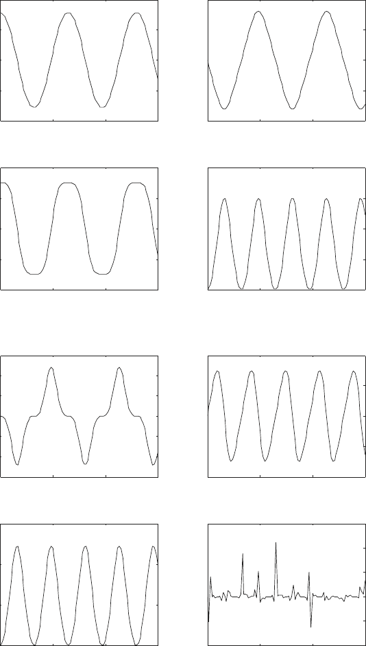
Some of the results from these simulations are shown in Fig. 6.3 and Fig.
6.4. Plots (i) and (ii) in Fig.6.3 show θ(t) and
˙
θ(t), which are are computed
using the model ex3a ide. Plots (iii) through (vi) in Fig 6.3 show q
1
(t), q
2
(t),
˙q
1
(t), ˙q
2
(t), y
5
(t) = λ(t) and y
6
(t), which are are computed using the model
ex3b ide. Recall that y
6
is the multiplier associated with the GGL stabilized
index-2 formulation, and this variable should be zero along the solution to
the equations of motion.
The plots shown in Fig. 6.4 compare the solutions obtained using the
models ex3a ide and ex3b ide. Here, we plot the errors:
e
1
(t) = |l sin θ(t) − q
1
(t)|,
e
2
(t) = |l cos θ(t) − q
2
(t)|, and
e
3
(t) = |q
1
(t)
2
+ q
2
(t)
2
− l
2
|,
where θ(t) is the result from the model ex3a ide, and q
1
(t), q
2
(t) are the
results from the model ex3b ide. The small values obtained for e
1
(t) and
e
2
(t) indicate that both models give essentially the same result. The small
values obtained for e
3
shows that the displacement constraint is satisfied, to
within the desired error tolerance (10
−6
).
Example 6.14.
2
+
v(t)
+
v
d
C
1
R
q
1
q
2
R
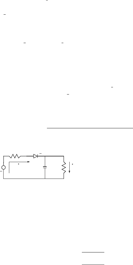
The power supply filter shown here has
the following model parameters; R
1
= 8
ohm, R
2
= 48 ohm, C = 3900 × 10
−6
farad, and v(t) = 12 sin 120πt. Also, the
current through the diode satisfies ˙q
1
=
I
s
(e
αv
d
−1), where the reverse saturation
current is I
s
= 10
−12
amp.
The thermal voltage is (1/α) = 25 × 10
−3
volt, and v
d
is the voltage across
the diode. Using the charges q
1
, q
2
as generalized displacements, and f
1
=
˙q
1
, f
2
= ˙q
2
as the corresponding flows, Lagrange’s equations of motion for
this system can be written as
0 = ˙q
1
− f
1
,
0 = ˙q
2
− f
2
,
0 = R
1
f
1
+
(q
1
− q
2
)
C
− v + v
d
,
0 = R
2
f
2
−
(q
1
− q
2
)
C
,
0 = f
1
− I
s
(e
αv
d
− 1).
(a)
We solve these equations of motion using the function ride with zero
initial conditions for all the variables, in the time interval 0 ≤ t ≤ 1. The
results of this simulation are shown in Fig. 6.5.
294 6 Dynamic System Analysis and Simulation
0 1 2 3
−2
−1
0
1
2
(i)
t
θ
0 1 2 3
−10
−5
0
5
10
(ii)
t
dθ/dt
0 1 2 3
−0.4
−0.2
0
0.2
0.4
(ii)
t
q
1
0 1 2 3
0
0.1
0.2
0.3
0.4
(iv)
t
q
2
0 1 2 3
−3
−2
−1
0
1
2
3
(v)
t
dq
1
/dt
0 1 2 3
−2
−1
0
1
2
(vi)
t
dq
2
/dt
0 1 2 3
0
5
10
15
(vii)
t
y
5
0 1 2 3
−4
−2
0
2
4
6
x 10
−5
(viii)
t
y
6
Fig. 6.3 Example 6.13
6.2 System Simulation 295
0 1 2 3
0
2
4
6
8
x 10
−8
(ix)
t
e
1
0 1 2 3
0
2
4
6
8
x 10
−8
(x)
t
e
2
0 1 2 3
0
1
2
3
4
x 10
−8
(xi)
t
e
3
Fig. 6.4 Example 6.13, continued.
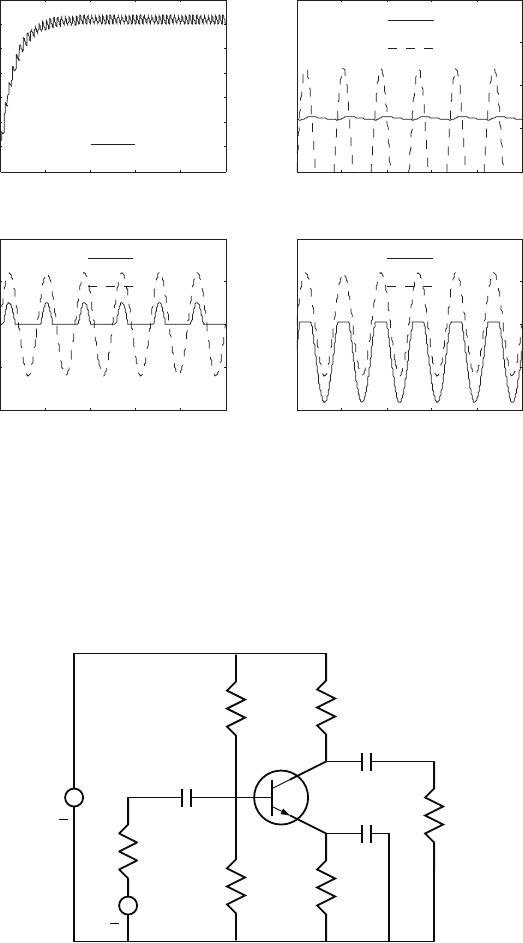
The plot (i) in Fig. 6.5 shows the voltage across the resistor R
2
, i.e.,
v
R
2
= R
2
f
2
. This plot covers the entire solution interval, and shows that the
system quickly approaches its steady-state response around t = 0.3 seconds.
The plot (ii) in Fig. 6.5 shows the voltage v
R
2
and the positive portion of
the input voltage v in the interval 0.9 ≤ t ≤ 1. This plot clearly shows the
variation (or ‘ripple’) in the voltage v
R
2
. The plot (iii) in Fig. 6.5 shows the
input voltage, v(t), and the voltage across the resistor R
1
, i.e., v
R
1
= R
1
f
1
.
Finally, the plot (iv) in Fig. 6.5 shows the input voltage, v(t), and the voltage
across the diode, i.e., v
d
(t).
These results clearly show the switching characteristics of the diode. In
particular, it can be seen that when the diode voltage v
d
attains a positive
value the current ˙q
1
> 0, which yields a positive voltage v
R
1
. On the other
hand, when v
d
< 0 we get ˙q
1
= 0, and hence, v
R
1
= 0. The net effect is that
the diode allows positive current flow when the voltage source v(t) is positive,
and no current flow when v(t) is negative.
Example 6.15.
In this example we consider the modeling and simulation of the transistor
296 6 Dynamic System Analysis and Simulation
0 0.2 0.4 0.6 0.8 1
0
1
2
3
4
5
6
7
t
volts
(i)
v
R2
0.9 0.92 0.94 0.96 0.98 1
−20
−10
0
10
20
t
volts
(iii)
v
R1
v
0.9 0.92 0.94 0.96 0.98 1
−20
−10
0
10
20
t
volts
(iv)
v
d
v
0.9 0.92 0.94 0.96 0.98 1
0
5
10
15
20
t
volts
(ii)
v
R2
v
Fig. 6.5 Example 6.14
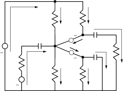
amplifier shown below. Here, the voltage source v
1
is constant, and provides
power to the system. The voltage source v
2
(t) is an input signal that is
amplified. The amplified signal drives the load resistor R
3
.
E
v
+
R
C
C
2
1
C
1
3
3
R
+
2
v
R
C
R
1
R
0
2
R
Amplifier circuit
Kinematic analysis:
6.2 System Simulation 297
The kinematic analysis of this circuit is performed using the node and flow
assignment shown in the diagram below. Here, the variables f
1
, f
2
, ···,
denote the flows (i.e., the currents) in the branches of the network. The dis-
placements (i.e., the charges) corresponding to these flows are q
1
, q
2
, etc.
This figure also shows an equivalent network model of the transistor. In this
model the current at the collector, f
c
, and emitter, f
e
, are determined by the
voltages v
be
and v
bc
as described by the Ebbers-Moll equations
f
e
f
c
−
I
ES
−I
S
I
S
−I
CS
e
αv
be
− 1
e
αv
bc
− 1
=
0
0
, (a)
where I
ES
, I
S
and I
CS
are constants for the transistor. (See Section 1.2.5.)
v
+
+
f
v
A
C
E
f
4
f
5
1
f
f
3
f
8
f
6
B
f
7
f
c
f
e
+
+
2
1
2
be
v
v
bc
Node and flow assignment
This network has B = 10 branches, and N = 5 nodes (A, B, C, E and the
ground). Hence, there are 6 = B − N + 1 independent loops in the network.
Since only 6 of the branch flows are independent we must construct 4 con-
straint equations to account for the ‘extra’ variables in the model. Applying
Kirchhoff’s current law at nodes A, B, C and E gives the following flow
constraints;
ψ
1
= f
1
− f
4
− f
5
= 0,
ψ
2
= f
2
− f
3
+ f
4
+ f
c
− f
e
= 0,
ψ
3
= f
5
− f
6
− f
c
= 0,
ψ
4
= f
e
− f
7
− f
8
= 0.
(b)
These constraints can be used to eliminate 4 of the flows from the model.
Here however, we will retain all flow/displacement variables in the model.
Applied effort analysis:
The virtual work done by the applied efforts v
1
and v
2
, and the implicit
efforts v
be
and v
bc
is
