Еврокод 3. Проектирование стальных конструкций. Часть 1-6. Прочность и устойчивость оболочек
Подождите немного. Документ загружается.

(4) The non-uniform distribution of pressure q
w
resulting from external wind loading on cylinders
(see
figure D.2) may, for the purpose of shell buckling design, be substituted by an equivalent uniform
external pressure:
q
eq
= k
w
q
w,max
...
(D.28)
where q
w,max
is the maximum wind pressure, and k
w
should be found as follows:
0, 46 1 0,1
w
C
r
k
t
θ
ω
= + ⋅
... (D.29)
with the value of k
w
not outside the range 0,65 ≤ k
w
≤ 1, and with C
θ
taken from table D.3 according
to the boundary conditions.
(5) The circumferential design stress to be introduced into 8.5 follows from:
,
( )
Ed eq s
r
q q
t
θ
σ
= +
... (D.30)
where q
s
is the internal suction caused by venting, internal partial vacuum or other phenomena.
D.1.
4 Shear
D.1.4.1 Critical shear buckling stresses
(1) The following expressions should be applied only to shells with boundary conditions BC1 or BC2
at both edges.
(2) The length of the shell segment should be characterised in terms of the dimensionless length
parameter
ω
:
l r l
r t
rt
ω
= =
... (D.31)
(3) The elastic critical shear buckling stress should be obtained from:
,
1
0,75
x
Rcr
t
EC
r
θ τ
τ
ω
=
... (D.32)
(4) For medium-length cylinders, which are defined by:
10 8, 7
r
t
ω
≤ ≤
... (D.33)
the factor C
τ
may be found as:
C
τ
= 1,0 ... (D.34)
(5) For short cylinders, which are defined by:
ω
< 10 ... (D.35)
EN 1993-1-6:2007 (Е)
76
the factor C
τ
may be obtained from:
3
42
1C
τ
ω
= +
... (
D.36)
(6) For long cylinders, which are defined by:
8, 7
r
t
ω
> ... (D.37)
the factor C
τ
may be obtained from:
1
3
t
C
r
τ
ω
=
... (D.38)
D.1.4.2 Shear buckling parameters
(1) The shear elastic imperfection reduction factor should be taken from table D.6 for the specified
fabrication tolerance quality class.
Table D.6: Values of
α
τ
based on fabrication quality
Fabrication tolerance
quality class
Description
α
τ
Class A Excellent 0,75
Class B High 0,65
Class C Normal 0,50
(2) The shear squash limit slenderness
λ
−
τ0
, the plastic range factor
β
, and the interaction exponent
η
should be taken as:
λ
−
τ0
= 0,40
β
= 0,60
η
= 1,0 ... (D.39)
(3) Cylinders need not be checked against shear shell buckling if they satisfy:
0.67
0,16
yk
r E
t f
≤
... (
D.40)
D.1.5 Meridional (axial) compression with coexistent internal pressure
D.1.5.1 Pressurised critical meridional buckling stress
(1) The elastic critical meridional buckling stress
σ
x,Rcr
may be assumed to be unaffected by the
prese
nce of internal pressure and may be obtained as specified in D.1.2.1.
D.1.5.2 Pressurised meridional buckling parameters
(1) The pressurised meridional buckling stress should be verified analogously to the unpressurised
meridional buckling stress as specified in 8.5 and D.1.2.2. However, the unpressurised elastic
EN 1993-1-6:2007 (Е)
77
imperfection reduction factor
α
x
should be replaced by the pressurised elastic imperfection reduction
fact
or
α
xp
.
(2)
The pressurised elastic imperfection reduction factor
α
xp
should be taken as the smaller of the two
foll
owing values:
α
xpe
is a factor covering pressure-induced elastic stabilisation;
α
xpp
is a factor covering pressure-induced plastic destabilisation
(3)
The factor
α
xpe
should be obtained from:
0,5
(1 )
0,3 /
s
xpe x x
s x
p
p
α α α
α
= + −
+
... (D.41)
,
s
s
x Rcr
p
r
p
t
σ
=
.
.
.
(D.42)
where:
p
s
is the smallest design value of local internal pressure at the location of the point
bein
g assessed, guaranteed to coexist with the meridional compression,
α
x
is the unpressurised meridional elastic imperfection reduction factor according to
D.1.
2.2, and
σ
x,Rcr
is the elastic critical meridional buckling stress according to D.1.2.1 (3).
(4)
The factor
α
xpe
should not be applied to cylinders that are long according to D.1.2.1 (6). In
addi
tion, it should not be applied unless one of the following two conditions are met:
the cylinder is medium-length according to D.1.2.1 (4);
the cylinder is short according to D.1.2.1 (5) and C
x
= 1 has been adopted in D.1.2.1 (3).
(
5)
The factor
α
xpp
should be obtained from:
( )
+
+
+
−
−=
1
21,1
12,1
1
11
2
x
2
2/3
2
2
x
xp
p
ss
s
s
p
g
λ
λ
α
... (D.43)
,
g
g
x
R
c
r
p
r
p
t
σ
=
...
(D.44)
EN 1993-1-6:2007 (Е)
78
1
400
r
s
t
= ⋅
... (D.45)
where:
p
g
is the largest design value of local internal pressure at the location of the point being
assessed that can coexist with the meridional compression;
λ
x
is the dimensionless shell slenderness parameter according to 8.5.2 (6);
σ
x,Rcr
is the elastic critical meridional buckling stress according to D.1.2.1 (3).
D.1.6 Combinations of meridional (axial) compression, circumferential (hoop)
compression and shear
(1) The buckling interaction parameters to be used in 8.5.3 (3) may be obtained from:
k
x
= 1,25 + 0,75
χ
x
... (D.46)
k
θ
= 1,25 + 0,75
χ
θ
... (D.47)
k
τ
= 1,75 + 0,25
χ
τ
... (D.48)
k
i
= (
χ
x
χ
θ
)
2
... (D.49)
where:
χ
x
,
χ
θ
,
χ
τ
are the buckling reduction factors defined in 8.5.2, using the buckling parameters
given in D.1.2 to D.1.4.
(2) The three membrane stress components should be deemed to interact in combination at any point
in the shell, except those adjacent to the boundaries. The buckling interaction check may be omitted for
all points that lie within the boundary zone length
l
R
adjacent to either end of the cylindrical segment.
The value of
l
R
is the smaller of:
l
R
= 0,1L ... (D.50)
and
l
R
≤ 0,16 r
r/t ... (D.51)
(3) Where checks of the buckling interaction at all points is found to be onerous, the following
provisions of (4) and (5) permit a simpler conservative assessment. If the maximum value of any of the
buckling-relevant membrane stresses in a cylindrical shell occurs in a boundary zone of length
l
R
adjacent to either end of the cylinder, the interaction check of 8.5.3 (3) may be undertaken using the
values defined in (4).
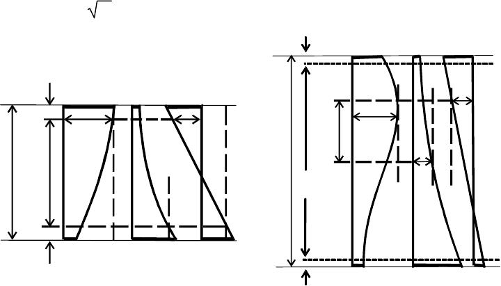
(4) Where the conditions of (3) are met, the maximum value of each of the buckling-relevant
membrane stresses occurring within the free length
l
f
(that is, outside the boundary zones, see figure
D.3a) may be used in the interaction check of 8.5.3 (3), where:
l
f
= L − 2
l
R
... (D.52)
(5) For long cylinders as defined in D.1.2.1 (6), the interaction-relevant groups introduced into the
interaction check may be restricted further than the provisions of paragraphs (3) and (4). The stresses
deemed to be in interaction-relevant groups may then be restricted to any section of length
l
int
falling
within the free remaining length
l
f
for the interaction check (see figure D.3b), where:
EN 1993-1-6:2007 (Е)
79
l
int
= 1,3 r
r/t ... (D.53)
a) in a short cylinder b) in a long cylinder
Figure D.3: Examples of interaction-relevant groups of membrane stress
compo
nents
(6) If (3)-(5) above do not provide specific provisions for defining the relative locations or separations
of interaction-relevant groups of membrane stress components, and a simple conservative treatment is
still required, the maximum value of each membrane stress, irrespective of location in the shell, may be
adopted into expression (8.19).
D.2 Unstiffened cylindrical shells of stepwise variable wall thickness
D.2.1 General
D.2.1.1 Notation and boundary conditions
(1) In this clause the following notation is used:
L overall cylinder length
r radius of cylinder middle surface
j an integer index denoting the individual cylinder sections with constant wall thickness
(from j = 1 to j = n)
t
j
the constant wall thickness of section j of the cylinder
l
j
the length of section j of the cylinder
(2) The following expressions may only be used for shells with boundary conditions BC 1 or BC 2 at
both edges (see 5.2.2 and 8.3), with no distinction made between them.
D.2.1.2 Geometry and joint offsets
(1) Provided that the wall thickness of the cylinder increases progressively stepwise from top to
bottom (see figure D.5a), the procedures given in this clause D.2 may be used.
l
R
l
R
L
l
l
f
σ
θ
σ
x
τ
L
l
f
σ
θ
σ
x
τ
l
R
l
int
l
R
EN 1993-1-6:2007 (Е)
80
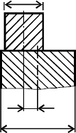
(2) Intended offsets e
0
between plates of adjacent sections (see figure D.4) may be treated as covered
by the following expressions provided that the intended value e
0
is less than the permissible value e
0,p
w
h
i
c
h
should be taken as the smaller of:
e
0,p
= 0,5 (t
max
– t
min
) ... (
D.54)
and
e
0,p
= 0,5 t
min
.
.. (
D.55)
where:
t
max
is the thickness of the thicker plate at the joint;
t
min
is the thickness of the thinner plate at the joint.
(
3) F
or cylinders with permissible intended offsets between plates of adjacent sections according
to (2), the radius r may be taken as the mean value of all sections.
(4) For cylinders with overlapping joints (lap joints), the provisions for lap-jointed construction given
in D.3 below should be used.
t
t
m
i
in
t
m
m
a
a
x
x
e
0
0
Figure D.4: Intended offset e
0
in a butt-jointed shell
D.2.2
Meridional (axial) compression
(1) Each cylinder section j of length
l
j
should be treated as an equivalent cylinder of overall length
l
= L and of uniform wall thickness t = t
j
according to D.1.2.
(2) F
or long equivalent cylinders, as governed by D.1.2.1 (6), the parameter C
xb
should be
conse
rvatively taken as C
xb
= 1, unless a better value is justified by more rigorous analysis.
D.2.3
Circumferential (hoop) compression
D.2.3.1 Critical circumferential buckling stresses
(1) If the cylinder consists of three sections with different wall thickness, the procedure of (4) to (7)
should be applied to the real sections a, b and c, see figure D.5b.
(2) If the cylinder consists of only one section (i.e. constant wall thickness), D.1 should be applied.
(3) If the cylinder consists of two sections of different wall thickness, the procedure of (4) to (7)
should be applied, treating two of the three fictitious sections, a and b, as being of the same thickness.
EN 1993-1-6:2007 (Е)
81
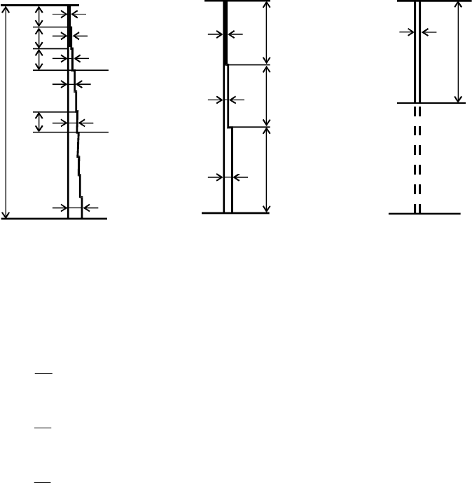
(4) If the cylinder consists of more than three sections with different wall thicknesses (see figure
D.5a), it should first be replaced by an equivalent cylinder comprising three sections a, b and c (see
figure D.5b). The length of its upper section,
l
a
, should extend to the upper edge of the first section that
has a
wall thickness greater than 1,5 times the smallest wall thickness t
1
, but should not comprise more
t
h
a
n
half the total length L of the cylinder. The length of the two other sections
l
b
and
l
c
should be
obtai
ned as follows:
l
b
=
l
a
and
l
c
= L − 2
l
a
, if
l
a
≤ L/3 ...
(D.56)
l
b
=
l
c
= 0,5 (L −
l
a
), if L/3 <
l
a
≤ L/2 ...
(D.57)
(a) Cylinder of stepwise variable
w
a
l
l
thickness
(b) Equivalent cylinder
comprising three sections
(c) Equivalent single cylinder
with uniform wall thickness
Figure D.5: Transformation of stepped cylinder into equivalent cylinder
(
5
)
T
he fictitious wall thicknesses t
a
, t
b
and t
c
of the three sections should be determined as the
weigh
ted average of the wall thickness over each of the three fictitious sections:
1
a j j
a
a
t t
=
∑
l
l
... (D.58)
1
b j j
b
b
t t
=
∑
l
l
... (
D.59)
1
c j j
c
c
t t
=
∑
l
l
... (D.60)
(6) The three-section-cylinder (i.e. the equivalent one or the real one respectively) should be replaced
by an equivalent single cylinder of effective length
l
eff
and of uniform wall thickness t = t
a
, s
ee figure
D.5c.
The effective length should be determined from:
l
eff
=
l
a
/
κ
... (D.61)
l
1
l
2
l
3
l
j
t
1
t
n
t
2
t
t
3
t
j
L
t
4
l
c
l
b
l
a
t
c
t
b
t
a
l
eff
t
a
EN 1993-1-6:2007 (Е)
82
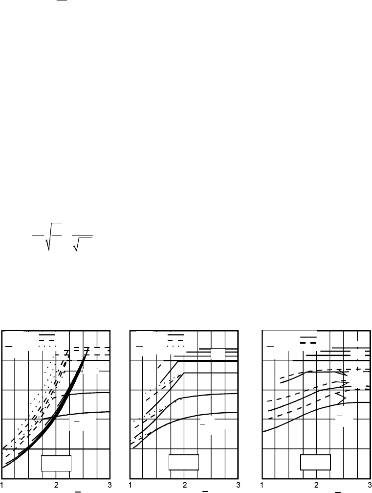
in which κ is a dimensionless factor obtained from figure D.6.
(7) For cylinder sections of moderate or short length, the elastic critical circumferential buckling stress
of each cylinder section j of the original cylinder of stepwise variable wall thickness should be
determined from:
, , , ,
a
Rcr j Rcr eff
j
t
t
θ θ
σ σ
=
... (D.62)
where
σ
θ
,Rcr,eff
is the elastic critical circumferential buckling stress derived from D.1.3.1 (3), D.1.3.1
(5) or D.1.3.1 (7), as appropriate, of the equivalent single cylinder of length
l
eff
according to paragraph
(6). The factor C
θ
in these expressions should be given the value C
θ
= 1,0.
NOTE: Expression D.62 may seem strange in that the resistance appears to be higher in thinner plates.
The reason is that the whole cylinder bifurcates at a single critical external pressure, and expression D.62
gives the membrane stress in each course at that instant. Since the external pressure is axially uniform,
these stress values are smaller in the thicker courses. It should be noted that the design membrane
circumferential stress, with which the resistance stresses will be compared in a design check, is also
smaller in the thicker courses (see figure D.7). If a stepped cylinder is elastic and under uniform external
pressure, the ratio of the design membrane circumferential stress to the design resistance stress is constant
throughout all courses.
(8) The length of the shell segment is characterised in terms of the dimensionless length parameter
ω
j
:
j j
j
j
j
r
r t
rt
ω
= =
l l
... (D.63)
(9) Where the cylinder section j is long, a second additional assessment of the buckling stress should
be made. The smaller of the two values derived from (7) and (10) should be used for the buckling design
check of the cylinder section j.
1
.
.
2
5
1
.
.
2
5
1
.
0
0
0
.
7
7
5
0
.
5
0
1
.
0
0
0
.
1
0
0
.
1
5
0
.
2
0
1
.
0
0
0
0
.
7
5
0
.
.
7
5
0
.
5
5
0
0
.
5
0
0
.
2
5
0
0
0
0
.
4
0
0
.
2
0
0
.
1
1
0
0
.
1
1
5
0
.
3
0
0
.
3
3
0
0
.
2
2
5
1
1
.
2
5
l
l
a
L
L
=
0
.
4
0
0
.
5
0
0
.
.
2
5
0
.
3
0
0
.
3
3
2
.
0
1
.
5
0
1
.
.
7
5
1
.
2
5
1
1
.
0
t
t
b
t
t
a
=
0
0
1
.
2
2
5
1
1
.
.
5
0
1
1
.
5
0
1
.
2
5
5
1
1
.
0
t
t
b
t
t
a
=
=
t
t
c
t
t
a
t
t
c
t
t
a
t
t
c
t
t
a
2
.
2
5
5
2
2
.
0
2
.
5
0
2
.
.
0
2
.
5
0
0
2
2
.
2
5
2
.
5
0
l
b
=
l
c
2
.
2
5
1
.
7
5
0
.
.
2
5
5
1
.
7
5
t
t
b
t
t
a
=
1
.
0
l
a
=
l
b
l
a
=
l
b
l
l
a
L
L
=
=
l
l
a
L
L
=
EN 1993-1-6:2007 (Е)
83
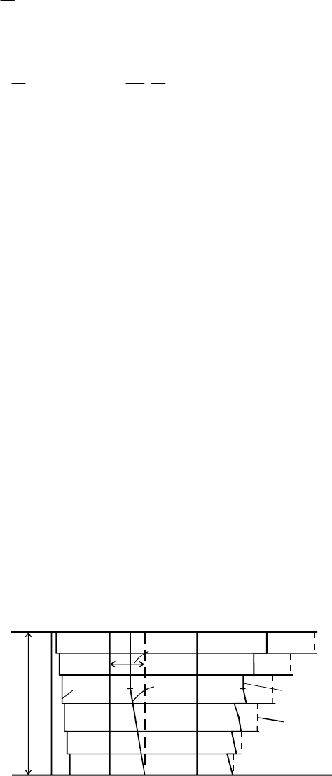
Figure D.6: Factor
κ
for determination of the effective length
l
eff
(10)
The cylinder section j should be treated as long if:
1,63
j
j
r
t
ω
>
... (D.64)
in which case the elastic critical circumferential buckling stress should be determined from:
4
2
, ,
1
0, 275 2, 03
j
Rcr j
j j
t
r
E
r t
θ
σ
ω
= + ⋅
... (D.65)
D.2.3.2 Buckling strength verification for circumferential compression
(1) For each cylinder section j, the conditions of 8.5 should be met, and the following check should be
carried out:
σ
θ
,Ed,j
≤
σ
θ
,Rcr,j
... (
D.66)
where:
σ
θ
,Ed,j
is the key value of the circumferential compressive membrane stress, as detailed in
the f
ollowing clauses;
σ
θ
,Rcr,j
is the design circumferential buckling stress, as derived from the elastic critical
circumferential buckling stress according to D.1.3.2.
(2) Provided that the design value of the circumferential stress resultant n
θ
,Ed
is constant throughout
the l
ength L, the key value of the circumferential compressive membrane stress in the section j, should
be taken as the simple value:
σ
θ
,Ed,j
= n
θ
,Ed
/ t
j
... (
D.67)
(3) If the design value of the circumferential stress resultant n
θ
,Ed
varies within the length L, the
key
value of the circumferential compressive membrane stress should be taken as a fictitious value
σ
θ
,Ed,j,mod
deter
mined from the maximum value of the circumferential stress resultant n
θ
,Ed
anywhere within the
lengt
h L divided by the local thickness t
j
(see figure D.7), determined as:
σ
θ
,Ed,j,mod
= max (n
θ
,Ed
) / t
j
... (
D.68)
L
t
j
j
n
n
θ
θE
d
d
n
θ
E
Ed
,
,
m
mod
σ
θ
E
Ed
j
j
σ
θ
θ
E
E
d
dj,m
o
od
EN 1993-1-6:2007 (Е)
84
Figure D.7: Key values of the circumferential compressive membrane stress in
cases where n
θ,Ed
va
ries within the length L
D.2.
4 Shear
D.2.4.1 Critical shear buckling stresses
(1) If no specific rule for evaluating an equivalent single cylinder of uniform wall thickness is
available, the expressions of D.2.3.1 (1) to (6) may be applied.
(2) The further determination of the elastic critical shear buckling stresses may on principle be
performed as in D.2.3.1 (7) to (10), but replacing the circumferential compression expressions from
D.1.3.1 by the relevant shear expressions from D.1.4.1.
D.2.4.2 Buckling strength verification for shear
(1) The rules of D.2.3.2 may be applied, but replacing the circumferential compression expressions by
the relevant shear expressions.
D.3 Unstiffened lap jointed cylindrical shells
D.3.1 General
D.3.1.1 Definitions
D.3.1.1.1
circumferential lap joint
A lap joint that runs in the circumferential direction around the shell axis.
D.3.1.1.2
meridional lap joint
A lap joint that runs parallel to the shell axis (meridional direction).
D.3.1.2 Geometry and stress resultants
(1) Where a cylindrical shell is constructed using lap joints (see figure D.8), the following provisions
may be used in place of those set out in D.2.
(2) The following provisions apply to lap joints that increase, and those that decrease the radius of the
middle surface of the shell.
(3) Where the lap joint runs in a circumferential direction around the shell axis (circumferential lap
joint), the provisions of D.3.2 should be used for meridional compression.
(4) Where many lap joints run in a circumferential direction around the shell axis (circumferential lap
joints) with changes of plate thickness down the shell, the provisions of D.3.3 should be used for
circumferential compression.
(5) Where a continuous lap joint runs parallel to the shell axis (unstaggered meridional lap joint), the
provisions of D.3.3 should be used for circumferential compression.
EN 1993-1-6:2007 (Е)
85