Еврокод 3. Проектирование стальных конструкций. Часть 1-6. Прочность и устойчивость оболочек
Подождите немного. Документ загружается.

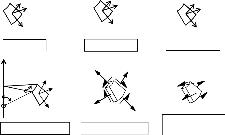
1.3.4 Stress resultants and stresses in a shell
1.3.4.1 membrane stress resultants
The membrane stress resultants are the forces per unit width of shell that arise as the integral of the
distribution of direct and shear stresses acting parallel to the shell middle surface through the
thickness of the shell. Under elastic conditions, each of these stress resultants induces a stress state
that is uniform through the shell thickness. There are three membrane stress resultants at any point
(see figure 1.1(e)).
1.3.4.2 bending stress resultants
The bending stress resultants are the bending and twisting moments per unit width of shell that arise
as the integral of the first moment of the distribution of direct and shear stresses acting parallel to the
shell middle surface through the thickness of the shell. Under elastic conditions, each of these stress
resultants induces a stress state that varies linearly through the shell thickness, with value zero and the
middle surface. There are two bending moments and one twisting moment at any point.
1.3.4.3 transverse shear stress resultants
The transverse stress resultants are the forces per unit width of shell that arise as the integral of the
distribution of shear stresses acting normal to the shell middle surface through the thickness of the
shell. Under elastic conditions, each of these stress resultants induces a stress state that varies
parabolically through the shell thickness. There are two transverse shear stress resultants at any point
(see figure 1.1(f)).
1.3.4.4 membrane stress
The membrane stress is defined as the membrane stress resultant divided by the shell thickness (see
figure 1.1(e)).
1.3.4.5 bending stress
The bending stress is defined as the bending stress resultant multiplied by 6 and divided by the square
of the shell thickness. It is only meaningful for conditions in which the shell is elastic.
1.3.5 Types of analysis
1.3.5.1 global analysis
An analysis that includes the complete structure, rather than individual structural parts treated
separately.
1.3.5.2 membrane theory analysis
An analysis that predicts the behaviour of a thin-walled shell structure under distributed loads by
assuming that only membrane forces satisfy equilibrium with the external loads.
1.3.5.3 linear elastic shell analysis (LA)
An analysis that predicts the behaviour of a thin-walled shell structure on the basis of the small
deflection linear elastic shell bending theory, related to the perfect geometry of the middle surface of
the shell.
1.3.5.4 linear elastic bifurcation (eigenvalue) analysis (LBA)
An analysis that evaluates the linear bifurcation eigenvalue for a thin-walled shell structure on the
basis of the small deflection linear elastic shell bending theory, related to the perfect geometry of the
middle surface of the shell. It should be noted that, where an eigenvalue is mentioned, this does not
relate to vibration modes.
1.3.5.5 geometrically nonlinear elastic analysis (GNA)
An analysis based on the principles of shell bending theory applied to the perfect structure, using a
linear elastic material law but including nonlinear large deflection theory for the displacements that
EN 1993-1-6:2007 (Е)
6
accounts full for any change in geometry due to the actions on the shell. A bifurcation eigenvalue
check is included at each load level.
1.3.5.6 materially nonlinear analysis (MNA)
An analysis based on shell bending theory applied to the perfect structure, using the assumption of
small deflections, as in 1.3.4.3, but adopting a nonlinear elasto-plastic material law.
1.3.5.7 geometrically and materially nonlinear analysis (GMNA)
An analysis based on shell bending theory applied to the perfect structure, using the assumptions of
nonlinear large deflection theory for the displacements and a nonlinear elasto-plastic material law. A
bifurcation eigenvalue check is included at each load level.
1.3.5.8 geometrically nonlinear elastic analysis with imperfections included (GNIA)
An analysis with imperfections explicitly included, similar to a GNA analysis as defined in 1.3.4.5,
but adopting a model for the geometry of the structure that includes the imperfect shape (i.e. the
geometry of the middle surface includes unintended deviations from the ideal shape). The
imperfection may also cover the effects of deviations in boundary conditions and / or the effects of
residual stresses. A bifurcation eigenvalue check is included at each load level.
1.3.5.9 geometrically and materially nonlinear analysis with imperfections included
(GMNIA)
An analysis with imperfections explicitly included, based on the principles of shell bending theory
applied to the imperfect structure (i.e. the geometry of the middle surface includes unintended
deviations from the ideal shape), including nonlinear large deflection theory for the displacements
that accounts full for any change in geometry due to the actions on the shell and a nonlinear elasto-
plastic material law. The imperfections may also include imperfections in boundary conditions and
residual stresses. A bifurcation eigenvalue check is included at each load level.
1.3.6 Stress categories used in stress design
1.3.6.1 Primary stresses
The stress system required for equilibrium with the imposed loading. This consists primarily of
membrane stresses, but in some conditions, bending stresses may also be required to achieve
equilibrium.
1.3.6.2 Secondary stresses
Stresses induced by internal compatibility or by compatibility with the boundary conditions,
associated with imposed loading or imposed displacements (temperature, prestressing, settlement,
shrinkage). These stresses are not required to achieve equilibrium between an internal stress state and
the external loading.
1.3.7 Special definitions for buckling calculations
1.3.7.1 critical buckling resistance
The smallest bifurcation or limit load determined assuming the idealised conditions of elastic material
behaviour, perfect geometry, perfect load application, perfect support, material isotropy and absence
of residual stresses (LBA analysis).
1.3.7.2critical buckling stress
The membrane stress associated with the critical buckling resistance.
1.3.7.3 plastic reference resistance
The plastic limit load, determined assuming the idealised conditions of rigid-plastic material
behaviour, perfect geometry, perfect load application, perfect support and material isotropy (modelled
using MNA analysis).
EN 1993-1-6:2007 (Е)
7
1.3.7.4 characteristic buckling resistance
The load associated with buckling in the presence of inelastic material behaviour, the geometrical and
structural imperfections that are inevitable in practical construction, and follower load effects.
1.3.7.5 characteristic buckling stress
The membrane stress associated with the characteristic buckling resistance.
1.3.7.6 design buckling resistance
The design value of the buckling load, obtained by dividing the characteristic buckling resistance by
the partial factor for resistance.
1.3.7.7 design buckling stress
The membrane stress associated with the design buckling resistance.
1.3.7.8 key value of the stress
The value of stress in a non-uniform stress field that is used to characterise the stress magnitudes in a
buckling limit state assessment.
1.3.7.9 fabrication tolerance quality class
The category of fabrication tolerance requirements that is assumed in design, see 8.4.
1.4 Symbols
(1) In addition to those given in EN 1990 and EN 1993-1-1, the following symbols are used:
(2) Coordinate system, see figure 1.1:
r radial coordinate, normal to the axis of revolution;
x meridional coordinate;
z axial coordinate;
θ
circumferential coordinate;
φ
meridional slope: angle between axis of revolution and normal to the meridian of the
shell;
(3) Pressures:
p
n
normal to the shell;
p
x
meridional surface loading parallel to the shell;
p
θ
circumferential surface loading parallel to the shell;
(
4) L
ine forces:
P
n
load per unit circumference normal to the shell;
P
x
load per unit circumference acting in the meridional direction;
P
θ
load per unit circumference acting circumferentially on the shell;
(
5) Membrane stress resultants:
n
x
meridional membrane stress resultant;
n
θ
circumferential membrane stress resultant;
n
xθ
membrane shear stress resultant;
(
6) B
ending stress resultants:
m
x
meridional bending moment per unit width;
EN 1993-1-6:2007 (Е)
8
m
θ
circumferential bending moment per unit width;
m
xθ
twisting shear moment per unit width;
q
xn
transverse shear force associated with meridional bending;
q
θn
transverse shear force associated with circumferential bending;
(
7) S
tresses:
σ
x
meridional stress;
σ
θ
circumferential stress;
σ
eq
von Mises equivalent stress (can also take negative values during cyclic loading);
τ
,
τ
xθ
in-plane shear stress;
τ
xn
,
τ
θn
meridional, circumferential transverse shear stresses associated with bending;
(8) D
isplacements:
u meridional displacement;
v circumferential displacement;
w displacement normal to the shell surface;
β
φ
meridional rotation, see 5.2.2;
(9) S
hell dimensions:
d internal diameter of shell;
L total length of the shell;
ℓ length of shell segment;
ℓ
g
gauge length for measurement of imperfections;
ℓ
gθ
gauge length in circumferential direction for measurement of imperfections;
ℓ
gw
gauge length across welds for measurement of imperfections;
ℓ
gx
gauge length in meridional direction for measurement of imperfections;
ℓ
R
limited length of shell for buckling strength assessment;
r
r
a
di
us of the middle surface, normal to the axis of revolution;
t thickness of shell wall;
t
max
maximum thickness of shell wall at a joint;
t
min
minimum thickness of shell wall at a joint;
t
a
ve
average thickness of shell wall at a joint;
β
apex half angle of cone;
EN 1993-1-6:2007 (Е)
9
Normal
Circumferential
Meridional
Directions
w
v
u
Displacements
n
θ
x
Coordinates
Membrane stresses
σ
x
σ
θ
τ
xθ
σ
x
σ
θ
z
p
θ
p
n
p
x
θ
φ
Surface pressures
Transverse shear
stresses
τ
θn
τ
xn
Figure 1.1: Symbols in shells of revolution
(10) Tolerances, see 8.4:
e eccentricity between the middle surfaces of joined plates;
U
e
accidental eccentricity tolerance parameter;
U
r
out-of-roundness tolerance parameter;
U
n
initial dimple imperfection amplitude parameter for numerical calculations;
U
0
initial dimple tolerance parameter;
∆w
0
tolerance normal to the shell surface;
(
11) P
roperties of materials:
E Young’s modulus of elasticity;
f
eq
von Mises equivalent strength;
f
y
yield strength;
f
u
ultimate strength;
ν
Poisson’s ratio;
(12) Parameters in strength assessment:
C coefficient in buckling strength assessment;
D cumulative damage in fatigue assessment;
F generalised action;
F
Ed
action set on a complete structure corresponding to a design situation (design
value
s);
F
Rd
calculated values of the action set at the maximum resistance condition of the
struc
ture
(design values);
r
Rk
characteristic reference resistance ratio (used with subscripts to identify the basis):
define
d as
EN 1993-1-6:2007 (Е)
10
the ratio (F
Rk
/ F
Ed
);
r
Rpl
plastic reference resistance ratio (defined as a load factor on design loads using
MNA
analysis);
r
Rcr
critical buckling resistance ratio (defined as a load factor on design loads using LBA
analysis);
NOTE: For consistency of symbols throughout the EN1993 the symbol for the reference resistance
ratio r
Ri
is used instead of the symbol R
Ri
. However, in order to avoid misunderstanding, it needs to be
noted here that the symbol R
Ri
is widely used in the expert field of shell structure design.
k calibration factor for nonlinear analyses;
k power of interaction expressions in buckling strength interaction expressions;
n number of cycles of loading;
α
elastic imperfection reduction factor in buckling strength assessment;
β
plastic range factor in buckling interaction;
γ
partial factor;
∆ range of parameter when alternating or cyclic actions are involved;
ε
p
plastic strain;
η
interaction exponent for buckling;
λ
−
relative slenderness of shell;
λ
−
ov
overall relative slenderness for the complete shell (multiple segments);
λ
−
0
squash limit relative slenderness (value of
λ
−
above which resistance reductions due
to instability or change of geometry occur);
λ
−
p
plastic limit relative slenderness (value of
λ
−
below which plasticity affects the
stability);
ω
relative length parameter for shell;
χ
buckling reduction factor for elastic-plastic effects in buckling strength assessment;
χ
ov
overall buckling resistance reduction factor for complete shell;
(13) S
ubscripts:
E value of stress or displacement (arising from design actions);
F actions;
M material;
R resistance;
cr critical buckling value;
d design value;
int internal;
k characteristic value;
max maximum value;
min minimum value;
nom nominal value;
pl plastic value;
EN 1993-1-6:2007 (Е)
11
u ultimate;
y yield.
(14) Further symbols are defined where they first occur.
1.5 Sign conventions
(1) Outward direction positive: internal pressure positive, outward displacement positive, except as
noted in (4).
(2) Tensile stresses positive, except as noted in (4).
NOTE: Compression is treated as positive in EN 1993-1-1.
(3) Shear stresses positive as shown in figures 1.1 and D.1.
(4) For simplicity, in section 8 and Annex D, compressive stresses are treated as positive. For
these cases, both external pressures and internal pressures are treated as positive where they occur.
2 Basis of design and modelling
2.1 General
(1)P
The basis of design shall be in accordance with EN 1990, as supplemented by the following.
(2) In particular, the shell should be designed in such a way that it will sustain all actions and
satisfy the following requirements:
overall equilibrium;
equilibrium between actions and internal forces and moments, see sections 6 and 8;
limitation of cracks due to cyclic plastification, see section 7;
limitation of cracks due to fatigue, see section 9.
(3) The design of the shell should satisfy the serviceability requirements set out in the appropriate
application standard (EN 1993 Parts 3.1, 3.2, 4.1, 4.2, 4.3).
(4) The shell may be proportioned using design assisted by testing. Where appropriate, the
requirements are set out in the appropriate application standard (EN 1993 Parts 3.1, 3.2, 4.1, 4.2, 4.3).
(5) All actions should be introduced using their design values according to EN 1991 and EN 1993
Parts 3.1, 3.2, 4.1, 4.2, 4.3 as appropriate.
2.2 Types of analysis
2.2.1 General
(1) One or more of the following types of analysis should be used as detailed in section 4,
depending on the limit state and other considerations:
Global analysis, see 2.2.2;
Membrane theory analysis, see 2.2.3;
Linear elastic shell analysis, see 2.2.4;
Linear elastic bifurcation analysis, see 2.2.5;
Geometrically nonlinear elastic analysis, see 2.2.6;
Materially nonlinear analysis, see 2.2.7;
Geometrically and materially nonlinear analysis, see 2.2.8;
Geometrically nonlinear elastic analysis with imperfections included, see 2.2.9;
Geometrically and materially nonlinear analysis with imperfections included, see 2.2.10.
EN 1993-1-6:2007 (Е)
12
2.2.2 Global analysis
(1) In a global analysis simplified treatments may be used for certain parts of the structure.
2.2.3 Membrane theory analysis
(1) A membrane theory analysis should only be used provided that the following conditions are
met:
the boundary conditions are appropriate for transfer of the stresses in the shell into support
reactions without causing significant bending effects;
the shell geometry varies smoothly in shape (without discontinuities);
the loads have a smooth distribution (without locally concentrated or point loads).
(2) A membrane theory analysis does not necessarily fulfil the compatibility of deformations at
boundaries or between shell segments of different shape or between shell segments subjected to
different loading. However, the resulting field of membrane forces satisfies the requirements of
primary stresses (LS1).
2.2.4 Linear elastic shell analysis (LA)
(1) The linearity of the theory results from the assumptions of a linear elastic material law and the
linear small deflection theory. Small deflection theory implies that the assumed geometry remains
that of the undeformed structure.
(2) An LA analysis satisfies compatibility in the deformations as well as equilibrium. The
resulting field of membrane and bending stresses satisfy the requirements of primary plus secondary
stresses (LS2 and LS4).
2.2.5 Linear elastic bifurcation analysis (LBA)
(1) The conditions of 2.2.4 concerning the material and geometric assumptions are met. However,
this linear bifurcation analysis obtains the lowest eigenvalue at which the shell may buckle into a
different deformation mode, assuming no change of geometry, no change in the direction of action of
the loads, and no material degradation. Imperfections of all kinds are ignored. This analysis provides
the elastic critical buckling resistance r
R
cr
, see 8.6 and 8.7 (LS3).
2.2.
6 Geometrically nonlinear elastic analysis (GNA)
(1) A GNA analysis satisfies both equilibrium and compatibility of the deflections under
conditions in which the change in the geometry of the structure caused by loading is included. The
resulting field of stresses matches the definition of primary plus secondary stresses (LS2).
(2) Where compression or shear stresses are predominant in some part of the shell, a GNA analysis
delivers the elastic buckling load of the perfect structure, including changes in geometry, that may be
of assistance in checking the limit state LS3, see 8.7.
(3) Where this analysis is used for a buckling load evaluation, the eigenvalues of the system must
be checked to ensure that the numerical process does not fail to detect a bifurcation in the load path.
2.2.7 Materially nonlinear analysis (MNA)
(1) The result of an MNA analysis gives the plastic limit load, which can be interpreted as a load
amplification factor r
Rpl
on the design value of the loads F
Ed
. This analysis provides the plastic
reference resistance ratio r
Rpl
used in 8.6 and 8.7.
(2) An MNA analysis may be used to verify limit state LS1.
(3) An MNA analysis may be used to give the plastic strain increment ∆ε during one cycle of
cyclic loading that may be used to verify limit state LS2.
EN 1993-1-6:2007 (Е)
13
2.2.8 Geometrically and materially nonlinear analysis (GMNA)
(1) The result of a GMNA analysis, analogously to 2.2.7, gives the geometrically nonlinear plastic
limit load of the perfect structure and the plastic strain increment, that may be used for checking the
limit states LS1 and LS2.
(2) Where compression or shear stresses are predominant in some part of the shell, a GMNA
analysis gives the elasto-plastic buckling load of the perfect structure, that may be of assistance in
checking the limit state LS3, see 8.7.
(3) Where this analysis is used for a buckling load evaluation, the eigenvalues of the system should
be checked to ensure that the numerical process does not fail to detect a bifurcation in the load path.
2.2.9 Geometrically nonlinear elastic analysis with imperfections included (GNIA)
(1) A GNIA analysis is used in cases where compression or shear stresses dominate in the shell. It
delivers elastic buckling loads of the imperfect structure, that may be of assistance in checking the
limit state LS3, see 8.7.
(2) Where this analysis is used for a buckling load evaluation (LS3), the eigenvalues of the system
should be checked to ensure that the numerical process does not fail to detect a bifurcation in the load
path. Care must be taken to ensure that the local stresses do not exceed values at which material
nonlinearity may affect the behaviour.
2.2.10 Geometrically and materially nonlinear analysis with imperfections included
(GMNIA)
(1) A GMNIA analysis is used in cases where compression or shear stresses are dominant in the
shell. It delivers elasto-plastic buckling loads for the "real" imperfect structure, that may be used for
checking the limit state LS3, see 8.7.
(2) Where this analysis is used for a buckling load evaluation, the eigenvalues of the system should
be checked to ensure that the numerical process does not fail to detect a bifurcation in the load path.
(3) Where this analysis is used for a buckling load evaluation, an additional GMNA analysis of the
perfect shell should always be conducted to ensure that the degree of imperfection sensitivity of the
structural system is identified.
2.3 Shell boundary conditions
(1) The boundary conditions assumed in the design calculation should be chosen in such a way as
to ensure that they achieve a realistic or conservative model of the real construction. Special attention
should be given not only to the constraint of displacements normal to the shell wall (deflections), but
also to the constraint of the displacements in the plane of the shell wall (meridional and
circumferential) because of the significant effect these have on shell strength and buckling resistance.
(2) In shell buckling (eigenvalue) calculations (limit state LS3), the definition of the boundary
conditions should refer to the incremental displacements during the buckling process, and not to total
displacements induced by the applied actions before buckling.
(3) The boundary conditions at a continuously supported lower edge of a shell should take into
account whether local uplifting of the shell is prevented or not.
(4) The shell edge rotation
β
φ
should be particularly considered in short shells and in the
calc
ulation of secondary stresses in longer shells (according to the limit states LS2 and LS4).
(5) The boundary conditions set out in 5.2.2 should be used in computer analyses and in selecting
expressions from Annexes A to D.
EN 1993-1-6:2007 (Е)
14
(6) The structural connections between shell segments at a junction should be such as to ensure
that the boundary condition assumptions used in the design of the individual shell segments are
satisfied.
3 Materials and geometry
3.1 Material properties
(1) T
he material properties of steels should be obtained from the relevant application standard.
(2) Where materials with nonlinear stress-strain curves are involved and a buckling analysis is
carried out under stress design (see 8.5), the initial tangent value of Young´s modulus E should be
replaced by a reduced value. If no better method is available, the secant modulus at the 0,2% proof
stress should be used when assessing the elastic critical load or elastic critical stress.
(3) In a global numerical analysis using material nonlinearity, the 0,2% proof stress should be used
to represent the yield stress f
y
in all relevant expressions. The stress-strain curve should be obtained
from EN 1993-1-5 Annex C for carbon steels and EN 1993-1-4 Annex C for stainless steels.
(4) The material properties apply to temperatures not exceeding 150°C.
NOTE: The national annex may give information about material properties at temperatures exceeding
150°C.
3.2 Design values of geometrical data
(1) The thickness t of the shell should be taken as defined in the relevant application standard. If no
application standard is relevant, the nominal thickness of the wall, reduced by the prescribed value of
the corrosion loss, should be used.
(2) The thickness ranges within which the rules of this Standard may be applied are defined in the
relevant EN 1993 application parts.
(3) The middle surface of the shell should be taken as the reference surface for loads.
(4) The radius r of the shell should be taken as the nominal radius of the middle surface of the
shell, measured normal to the axis of revolution.
(5) The buckling design rules of this Standard should not be applied outside the ranges of the r/t
ratio set out in section 8 or Annex D or in the relevant EN 1993 application parts.
3.3 Geometrical tolerances and geometrical imperfections
(1) Tolerance values for the deviations of the geometry of the shell surface from the nominal values
are defined in the execution standards due to the requirements of serviceability. Relevant items are:
out-of-roundness (deviation from circularity),
eccentricities (deviations from a continuous middle surface in the direction normal to the shell
across the junctions between plates),
local dimples (local normal deviations from the nominal middle surface).
NOTE: The requirements for execution are set out in EN 1090, but a fuller description of these
tolerances is given here because of the critical relationship between the form of the tolerance measure,
its amplitude and the evaluated resistance of the shell structure.
(2) If the limit state of buckling (LS3, as described in 4.1.3) is one of the ultimate limit states to be
considered, additional buckling-relevant geometrical tolerances have to be observed in order to keep
the geometrical imperfections within specified limits. These buckling-relevant geometrical tolerances
are quantified in section 8 or in the relevant EN 1993 application parts.
EN 1993-1-6:2007 (Е)
15