Еврокод 3. Проектирование стальных конструкций. Часть 1-6. Прочность и устойчивость оболочек
Подождите немного. Документ загружается.


χ
=
2
λ
α
when
λλ
≤
p
... (8.15)
where:
α
is the elastic imperfection reduction factor
β
is the plastic range factor
η
is the interaction exponent
λ
0
is the squash limit relative slenderness
NOTE 1: The values of these parameters should be taken from Annex D. Where Annex D does not
define the values of these parameters, they may be given by the National Annex.
NOTE 2: Expression (8.15) describes the elastic buckling stress, accounting for geometric
imperfections. In this case, where the behaviour is entirely elastic, the characteristic buckling stresses
may alternatively be determined directly from
σ
x,Rk
=
α
x
σ
x,Rcr
,
σ
θ,Rk
=
α
θ
σ
θ,Rcr
, and
τ
xθ,Rk
=
α
τ
τ
xθ,Rcr
.
(5)
The value of the plastic limit relative slenderness
p
λ
should be determined from:
β
α
λ
−
=
1
p
... (8.16)
(6) The relative shell slenderness parameters for different stress components should be determined
from:
Rcrx,ykx
/
σλ
f= ,
Rcr,yk
/
θθ
σλ
f= ,
(
)
Rcr,xyk
/3/
θτ
τλ
f= ... (8.17)
(7) The elastic critical buckling stresses
σ
x,Rcr
,
σ
θ,Rcr
and
τ
xθ,Rcr
should be obtained by means of the
rele
vant expressions in Annex D.
(8) Where no appropriate expressions are given in Annex D, the elastic critical buckling stresses
may be extracted from a numerical LBA analysis of the shell under the buckling-relevant
combinations of actions defined in 8.1. For the conditions that this analysis must satisfy, see 8.6.2 (5)
and (6).
8.5.3 Stress limitation (buckling strength verification)
(1) Although buckling is not a purely stress-initiated failure phenomenon, the buckling limit state,
with
in this section, should be represented by limiting the design values of membrane stresses. The
influence of bending effects on the buckling strength may be neglected provided they arise as a result
of meeting boundary compatibility requirements. In the case of bending stresses from local loads or
from thermal gradients, special consideration should be given.
(2) Depending on the loading and stressing situation, one or more of the following checks for the
key values of single membrane stress components should be carried out:
σ
x,Ed
≤
σ
x,Rd
,
σ
θ,Ed
≤
σ
θ,Rd
,
τ
xθ,Ed
≤
τ
xθ,Rd
...
(8.18)
(3) If more than one of the three buckling-relevant membrane stress components are present under
the actions under consideration, the following interaction check for the combined membrane stress
state should be carried out:
, , , , ,
, , , , ,
1
x
k k k
x Ed x E
d Ed Ed x Ed
i
x Rd x Rd Rd Rd x Rd
k
θ τ
θ θ θ
θ θ θ
σ σ σ σ τ
σ σ σ
σ τ
− + + ≤
...
(8.19)
EN 1993-1-6:2007 (Е)
36
where
σ
x,Ed
,
σ
θ,Ed
and
τ
xθ,Ed
are the interaction-relevant groups of the significant values of
comp
ressive and shear membrane stresses in the shell and the values of the buckling interaction
parameters k
x
, k
θ
, k
τ
and
k
i
are given in Annex D.
(4)
Where
σ
x,Ed
or
σ
θ,Ed
is tensile, its value should be taken as zero in expression (8.19).
NOTE: For axially compressed cylinders with internal pressure (leading to circumferential tension)
special provisions are made in Annex D. The resulting value of
σ
x,Rd
accounts for both the
strengthening effect of internal pressure on the elastic buckling resistance and the weakening effect of
the elastic-plastic elephant’s foot phenomenon (expression D.43). If the tensile
σ
θ,Ed
is then taken as
zero in expression (8.19), the buckling strength is accurately represented.
(5) The locations and values of each of the buckling-relevant membrane stresses to be used
together in combination in expression (8.19) are defined in Annex D.
(6) Where the shell buckling condition is not included in Annex D, the buckling interaction
parameters may be conservatively estimated using:
k
x
= 1,0 + χ
x
2
…(8.20)
k
θ
= 1,0 + χ
θ
2
…(8.21)
k
τ
= 1,5 + 0,5 χ
τ
2
…(8.22)
k
i
= (χ
x
χ
θ
)
2
…(8.23)
NOTE: These rules may sometimes be very conservative, but they include the two limiting cases
which are well established as safe for a wide range of cases:
a) in very thin shells, the interaction between
σ
x
and
σ
θ
is approximately linear; and
b) in very thick shells, the interaction becomes that of von Mises.
8.6 Design by global numerical analysis using MNA and LBA analyses
8.6.
1 Design value of actions
(1) The design values of actions should be taken as in 8.1 (1).
8.6.2 Design value of resistance
(1) The design buckling resistance should be determined from the amplification factor r
Rd
applied
to the design values F
Ed
of the combination of actions for the relevant load case.
(
2
)
The design buckling resistance
Rd Rd Ed
F r F
= ⋅ should be obtained from the plastic reference
resistance
pl
R Rpl Ed
F r F
= ⋅ and the elastic critical buckling resistance
cr Rcr Ed
F r F
= ⋅ , combining these
to find the characteristic buckling resistance
k
R Rk Ed
F r F
= ⋅ . The partial factor
γ
M1
should then be
used
to obtain the design resistance.
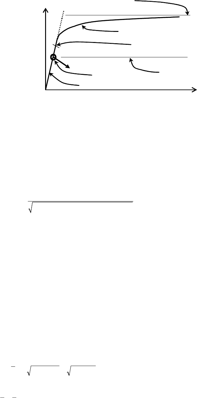
(3) The plastic reference resistance ratio
Rpl
r
(see figure 8.5) should be obtained by materially non-
linear analysis (MNA) as the plastic limit load under the applied combination of actions. This load
ratio
Rpl
r
may be taken as the largest value attained in the analysis, ignoring the effect of strain
hardening.
EN 1993-1-6:2007 (Е)
37
r
Rpl
sm
all displacement theory
plastic limit load
r
Rcr
from linear
elastic bifurcation
LA
Load factor
on design
actions
r
Deformation
MNA
LBA
r
Rpl
estimate from LA
Figure 8.5: Definition of plastic reference resistance ratio r
Rpl
and critical
buck
ling resistance ratio r
Rcr
derived from global MNA and LBA analyses
(4) Where it is not possible to undertake a materially non-linear analysis (MNA), the plastic
reference resistance ratio r
Rpl
may be conservatively estimated from linear shell analysis (LA)
conducted using the design values of the applied combination of actions using the following
procedure. The evaluated membrane stress resultants n
x,Ed
, n
θ,Ed
and n
xθ,Ed
at any point in the shell
should be used to estimate the plastic reference resistance from:
2 2 2
, , , , ,
yk
Rpl
x Ed x Ed Ed Ed x Ed
t f
r
n n n n n
θ θ θ
⋅
=
− ⋅ + +
...
(8.24)
The lowest value of plastic resistance ratio so calculated should be taken as the estimate of the plastic
reference resistance ratio r
Rpl
.
NOTE: A safe estimate of r
Rpl
can usually be obtained by applying expression (8.24) in turn at the
three points in the shell where each of the three buckling-relevant membrane stress resultants attains its
highest value, and using the lowest of these three estimates as the relevant value of r
Rpl
.
(5) The elastic critical buckling resistance ratio r
Rcr
should be determined from an eigenvalue
analysis (LBA) applied to the linear elastic calculated stress state in the geometrically perfect shell
(LA) under the design values of the load combination. The lowest eigenvalue (bifurcation load
factor) should be taken as the elastic critical buckling resistance ratio r
Rcr
, see figure 8.5.
(6)
It should be verified that the eigenvalue algorithm that is used is reliable at finding the
eigenmode that leads to the lowest eigenvalue. In cases of doubt, neighbouring eigenvalues and their
eigenmodes should be calculated to obtain a fuller insight into the bifurcation behaviour of the shell.
The analysis should be carried out using software that has been authenticated against benchmark
cases with physically similar buckling characteristics.
(7) The overall relative slenderness
ov
λ
for the complete shell should be determined from:
RcrRplRcrRplov
// rrFF ==
λ
... (8.25)
(8) The overall buckling reduction factor
χ
ov
should be determined as
(
)
ovovovov,0ovov
,,,,
ηβαλλχ
f= using 8.5.2 (4), in which
α
ov
is the overall elastic imperfection
EN 1993-1-6:2007 (Е)
38

reduction factor,
β
ov
is the plastic range factor,
η
ov
is the interaction exponent and
ov,0
λ
is the squash
limit relative slenderness.
(9) The evaluation of the factors
ov,0
λ
, r
Rov
,
β
ov
and
η
ov
should take account of the imperfection
sens
itivity, geometric nonlinearity and other aspects of the particular shell buckling case.
Conservative values for these parameters should be determined by comparison with known shell
buckling cases (see Annex D) that have similar buckling modes, similar imperfection sensitivity,
similar geometric nonlinearity, similar yielding sensitivity and similar postbuckling behaviour. The
value of r
Rov
should also take account of the appropriate fabrication tolerance quality class.
NOTE: Care should be taken in choosing an appropriate value of r
Rov
when this approach is used
on shell geometries and loading cases where snap-through buckling may occur. Such cases include
conical and spherical caps and domes under external pressure or on supports that can displace radially.
The appropriate value of r
Rov
should also be chosen with care when the shell geometry and load case
produce conditions that are highly sensitive to changes of geometry, such as at unstiffened junctions
between cylindrical and conical shell segments under meridional compressive loads (e.g. in chimneys).
The commonly reported elastic shell buckling loads for these special cases are normally based on
geometrically nonlinear analysis applied to a perfect or imperfect geometry, which predicts the snap-
through buckling load. By contrast, the methodology used here adopts the linear bifurcation load as
the reference elastic critical buckling resistance, and this is often much higher than the snap-through
load. The design calculation must account for these two sources of reduced resistance by an
appropriate choice of the overall elastic imperfection reduction factor r
Rov
. This choice must include
the effect of both the geometric nonlinearity (that can lead to snap-through) and the additional strength
reduction caused by geometric imperfections.
(10) If the provisions of (9) cannot be achieved beyond reasonable doubt, appropriate tests should be
carried out, see EN 1990, Annex D.
(11) If specific values of r
Rov
,
β
ov
,
η
ov
and
ov,0
λ
are not available according to (9) or (10), the
values for an axially compressed unstiffened cylinder may be adopted, see D.1.2.2. Where snap-
through is known to be a possibility, appropriate further reductions in r
Rov
should be considered.
(12)
The characteristic buckling resistance ratio r
Rk
should be obtained from:
r
Rk
=
χ
ov
r
Rpl
...
(8.26)
where:
r
Rpl
is the plastic reference resistance ratio.
(13)
The design buckling resistance ratio r
Rd
should be obtained from:
r
Rd
= r
Rk
/
γ
M1
...
(8.27)
where:
γ
M1
is the partial factor for resistance to buckling according to 8.5.2 (2).
8.6.3 Buckling strength verification
(1) It should be verified that:
or r 1
Ed Rd Rd Ed Rd
F F r F
≤ = ⋅ ≥
... (8.28)
EN 1993-1-6:2007 (Е)
39
8.7 Design by global numerical analysis using GMNIA analysis
8.7.1 Design values of actions
(1) The design values of actions should be taken as in 8.1 (1).
8.7.2 Design value of resistance
(1) The design buckling resistance should be determined as a load factor r
R
applied to the design
v
alu
es F
Ed
of the combination of actions for the relevant load case.
(2)
The characteristic buckling resistance ratio r
Rk
should be found from the imperfect elastic-
plastic buckling resistance ratio r
R,GMNIA
, adjusted by the calibration factor k
GMNIA
. The design
b
u
c
k
ling resistance ratio r
Rd
should then be found using the partial factor
γ
M1
.
(3)
To determine the imperfect elastic-plastic buckling resistance ratio r
R,GMNIA
, a GMNIA
analysis of the geometrically imperfect shell under the applied combination of actions should be
carried out, accompanied by an eigenvalue analysis to detect possible bifurcations in the load path.
NOTE: Where plasticity has a significant effect on the buckling resistance, care should be taken to
ensure that the adopted imperfection mode induces some pre-buckling shear strains, because the shear
modulus is very sensitive to small plastic shear strains. In certain shell buckling problems (e.g. shear
buckling of annular plates), if this effect is omitted, the eigenvalue analysis may give a considerable
overestimate of the elastic-plastic buckling resistance.
(4) An LBA analysis should first be performed on the perfect structure to determine the elastic
critical buckling resistance ratio r
Rcr
of the perfect shell. An MNA should next be performed on the
perf
ect structure to determine the perfect plastic reference resistance ratio r
Rpl
. These two resistance
r
a
t
i
os should then be used to establish the overall relative slenderness
λ
−
ov
for the complete shell
according to expression 8.25.
(5) A GMNA analysis should then be performed on the perfect structure to determine the perfect
elastic-plastic buckling resistance ratio r
R,GMNA
. This resistance ratio should be used later to verify
that
the effect of the chosen geometric imperfections has a sufficiently deleterious effect to give
confidence that the lowest resistance has been obtained. The GMNA analysis should be carried out
under the applied combination of actions, accompanied by an eigenvalue analysis to detect possible
bifurcations in the load path.
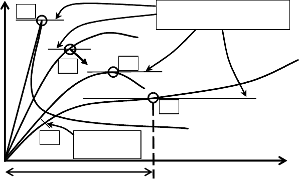
(6) The imperfect elastic-plastic buckling resistance ratio r
R,GMNIA
should be found as the lowest
load factor r
R
obtained from the three following criteria C1, C2 and C3, see figure 8.6:
C
r
i
t
erion C1: The maximum load factor on the load-deformation-curve (limit load);
Criterion C2: The bifurcation load factor, where this occurs during the loading path before
reaching the limit point of the load-deformation-curve;
Criterion C3: The largest tolerable deformation, where this occurs during the loading path
before reaching a bifurcation load or a limit load.
(7) The largest tolerable deformation should be assessed relative to the conditions of the individual
structure. If no other value is available, the largest tolerable deformation may be deemed to have been
reached when the greatest local rotation of the shell surface (slope of the surface relative to its
original geometry) attains the value
β
.
NOTE: The National Annex may choose the value of
β
. The value
β
= 0,1 radians is
recommended.
EN 1993-1-6:2007 (Е)
40
Deformation
Load factor
on design
actions
r
r
R,GMNIA
is the lowest of
these alternative measures
largest tolerable
deformation
C1
C2
C2
C3
C4
First yield
safe estimate
Figure 8.6: Definition of buckling resistance from global GMNIA analysis
(8)
A conservative assessment of the imperfect elastic-plastic buckling resistance ratio r
R,GMNIA
may
be obtained using a GNIA analysis of the geometrically imperfect shell under the applied
combination of actions. In this case, the following criterion should be used to determine the lowest
load factor r
R
:
Crit
erion C4: The load factor at which the equivalent stress at the most highly stressed point on
the shell surface reaches the design value of the yield stress f
yd
= f
yk
/
γ
M0
, see figure 8.6.
NOTE: It should be noted that GMNA, GMNIA and GNIA analyses must always be undertaken
wit
h regular eigenvalue checks to ensure that any possible bifurcation on the load path is detected.
(9) In formulating the GMNIA (or GNIA) analysis, appropriate allowances should be incorporated
to c
over the effects of imperfections that cannot be avoided in practice, including:
a) geometric imperfections, such as:
deviations from the nominal geometric shape of the middle surface (pre-deformations, out-of-
roundness);
irregularities at and near welds (minor eccentricities, shrinkage depressions, rolling curvature
errors);
deviations from nominal thickness;
lack of evenness of supports.
b) material imperfections, such as:
residual stresses caused by rolling, pressing, welding, straightening etc.;
inhomogeneities and anisotropies.
NOTE: Further possible negative influences on the imperfect elastic-plastic buckling resistance
rat
io r
R,GMNIA
, such as ground settlements or flexibilities of connections or supports, are not classed
as i
mperfections in the sense of these provisions.
(10)
Imperfections should be allowed for in the GMNIA analysis by including appropriate additional
quantities in the analytical model for the numerical computation.
(11) The imperfections should generally be introduced by means of equivalent geometric
imperfections in the form of initial shape deviations perpendicular to the middle surface of the perfect
shell, unless a better technique is used. The middle surface of the geometrically imperfect shell
should be obtained by superposition of the equivalent geometric imperfections on the perfect shell
geometry.
EN 1993-1-6:2007 (Е)
41

(12) The pattern of the equivalent geometric imperfections should be chosen in such a form that it
has the most unfavourable effect on the imperfect elastic-plastic buckling resistance ratio r
R,GMNIA
of
t
h
e
shell. If the most unfavourable pattern cannot be readily identified beyond reasonable doubt, the
analysis should be carried out for a sufficient number of different imperfection patterns, and the worst
case (lowest value of r
R,GMNIA
) should be identified.
(13)
The eigenmode-affine pattern should be used unless a different unfavourable pattern can be
justified.
NOTE: The eigenmode affine pattern is the critical buckling mode associated with the elastic
critical buckling resistance ratio r
Rcr
based on an LBA analysis of the perfect shell.
(14) The pattern of the equivalent geometric imperfections should, if practicable, reflect the
constructional detailing and the boundary conditions in an unfavourable manner.
(15) Notwithstanding (13) and (14), patterns may be excluded from the investigation if they can be
eliminated as unrealistic because of the method of fabrication, manufacture or erection.
(16) Modification of the adopted mode of geometric imperfections to include realistic structural
details (such as axisymmetric weld depressions) should be explored.
NOTE: The National Annex may define additional requirements for the assessment of appropriate
patterns of imperfections.
(17)
The sign of the equivalent geometric imperfections should be chosen in such a manner that the
maximum initial shape deviations are unfavourably oriented towards the centre of the shell curvature.
(18) The amplitude of the adopted equivalent geometric imperfection form should be taken as
dependent on the fabrication tolerance quality class. The maximum deviation of the geometry of the
equivalent imperfection from the perfect shape
∆w
0,eq
should be the larger of ∆w
0,eq,1
and ∆w
0,eq,2
,
where:
∆w
0,eq,1
=
l
g
U
n1
... (8.29)
∆w
0,eq,2
= n
i
t U
n2
...
(8.30)
where:
l
g
is all relevant gauge lengths according to 8.4.4 (2);
t is
the local shell wall thickness;
n
i
is a multiplier to achieve an appropriate tolerance level;
U
n1
and U
n2
are the dimple imperfection amplitude parameters for the relevant fabrication
tole
rance quality class.
NOTE 1: The National Annex may choose the value of n
i
. The value n
i
= 25 is recommended.
NOTE 2: Values for the dimple tolerance parameter U
n1
and U
n2
may be obtained from the National
Annex. The recommended values are given in Table 8.5.
Table 8.5: Recommended values for dimple imperfection amplitude
p
a
r
a
meters U
n1
and U
n2
Fabrication tolerance quality class Description Recommended
value of U
n1
Recommended
value of U
n2
Class A Excellent 0,010 0,010
Class B High 0,016 0,016
Class C Normal 0,025 0,025
EN 1993-1-6:2007 (Е)
42

(19) The amplitude of the geometric imperfection in the adopted pattern of the equivalent geometric
imperfection should be interpreted in a manner which is consistent with the gauge length method, set
out in 8.4.4 (2), by which it is defined.
(20) Additionally, it should be verified that an analysis that adopts an imperfection whose amplitude
is 10% smaller than the value
∆w
0,eq
found in (18) does not yield a lower value for the ratio r
R,GMNIA
.
I
f
a
lower value is obtained, the procedure should be iterated to find the lowest value of the ratio
r
R,GMNIA
as the amplitude is varied.
(21)
If follower load effects are possible, either they should be incorporated in the analysis, or it
should be verified that their influence is negligible.
(22) For each calculated value of the imperfect elastic-plastic buckling resistance r
R,GMNIA
, the ratio
of the imperfect to perfect resistance (r
R,GMNIA
/r
R,GMNA
) should be determined and compared with
valu
es of r
R
found using the procedures of 8.5 and Annex D, to verify that the chosen geometric
i
m
p
e
rfection has a deleterious effect that is comparable with that obtained from a lower bound to test
results.
NOTE: Where the resistance is dominated by plasticity effects, the ratio (r
R,GMNIA
/r
R,GMNA
) will be
much larger than the elastic imperfection reduction factor
α
, and no close comparison can be
expected. However, where the resistance is controlled by buckling phenomena that are substantially
elastic, the ratio (r
R,GMNIA
/r
R,GMNA
) should be only a little higher than the value determined by hand
calculation, and the factors leading to the higher value should be considered.
(23) The reliability of the numerically determined imperfect elastic-plastic buckling resistance ratio
r
R,GMNIA
should be checked by one of the following alternative methods:
a) by using the same program to calculate values r
R,GMNIA
,
check
for other shell buckling cases for
which characteristic buckling resistance ratio values r
Rk,known,check
are known. The check
c
a
s
e
s should use basically similar imperfection assumptions and be similar in their buckling
controlling parameters (such as relative shell slenderness, postbuckling behaviour,
imperfection-sensitivity, geometric nonlinearity and material behaviour);
b) by comparison of calculated values (r
R,GMNIA
,check
) against test results (r
R,test,known,check
).
The
check cases should satisfy the same similarity conditions given in (a).
NOTE 1: Other shell buckling cases for which the characteristic buckling resistance ratio values
r
Rk,known,check
are known may be found from the scientific literature on shell buckling. It should be
noted that the hand calculations of 8.5 and Annex D are derived as general lower bounds on test
results, and these sometimes lead to such low assessed values for the characteristic buckling resistance
that they cannot be easily obtained numerically.
NOTE 2: Where test results are used, it should be established that the geometric imperfections present
in the test may be expected to be representative of those that will occur in practical construction.
(24) Depending on the results of the reliability checks, the calibration factor k
GMNIA
should be
evaluated, as appropriate, from:
Rk,known,check R,test,known,check
GMNIA GMNIA
R,GMNIA,check R,GMNIA,check
or
r r
k k
r r
= =
...
(8.31)
where:
r
Rk,known,check
is the known characteristic value;
r
R,test,known,check
is the known test result;
r
R,GMNIA,check
is the calculation outcome for the check buckling case or the test
buck
ling case, as appropriate.
EN 1993-1-6:2007 (Е)
43
(25) Where test results are used to determine k
GMNIA
, and the calculated value of k
GMNIA
exceeds 1,0,
the adopted value should be k
GMNIA
= 1,0.
(26) Where a known characteristic value based on existing established theory is used to determine
k
GMNIA
, and the calculated value of k
GMNIA
lies outside the range 0,8 < k
GMNIA
< 1,2, this procedure
should not be used. The GMNIA result should be deemed invalid and further calculations undertaken
to establish the causes of the discrepancy.
(27) The characteristic buckling resistance ratio should be obtained from:
r
Rk
= k
GMNIA
r
R,GMNIA
... (8.32)
where:
r
R,GMNIA
is the calculated imperfect elastic-plastic buckling resistance ratio;
k
GMNIA
is the calibration factor.
8.7.3 Buckling strength verification
(1) The design buckling resistance ratio r
Rd
should be obtained from:
r
Rd
= r
Rk
/
γ
M1
... (8.33)
where:
γ
M1
is the partial factor for resistance to buckling according to 8.5.2 (2).
(2) It should be verified that:
or 1
Ed Rd Rd Ed Rd
F F r F r
≤ = ⋅ ≥
... (8.34)
EN 1993-1-6:2007 (Е)
44
9 Fatigue limit state (LS4)
9.1 Design values of actions
(1) The design values of the actions for each load case should be taken as the varying parts of the
total action representing the anticipated action spectrum throughout the design life of the structure.
(2) The relevant action spectra should be obtained from EN 1991 in accordance with the definitions
given in the appropriate application parts of EN 1993.
9.2 Stress design
9.2.
1 General
(1) The fatigue assessment presented in EN 1993-1-9 should be used, except as provided here.
(
2
)
P
The partial factor for resistance to fatigue
γ
Mf
shall be taken from the relevant application
stan
dard.
NOTE: The value of the partial factor
γ
Mf
may be defined in the National Annex. Where no
application standard exists for the form of construction involved, or the application standard does not
define the relevant values of
γ
Mf
, the value of
γ
Mf
should be taken from EN 1993-1-9. It is
recommended that the value of
γ
Mf
should not be taken as smaller than
γ
Mf
= 1,1.
9.2.2 Design values of stress range
(1) Stresses should be determined by a linear elastic analysis of the structure subject to the design
valu
es of the fatigue actions.
(2) In each verification of the limit state, the design value of the fatigue stress should be taken as
the larger stress range
∆
σ
of the values on the two surfaces of the shell, and based on the sum of the
primary and the secondary stresses.
(3) Depending upon the fatigue assessment carried out according to EN 1993-1-9, either nominal
stress ranges or geometric stress ranges should be evaluated.
(4) Nominal stress ranges may be used if 9.2.3 (2) is adopted.
(5) Geometric stress ranges should be used for construction details that differ from those of
9.2.3 (2).
(6) The geometric stress range takes into account only the overall geometry of the joint, excluding
local stresses due to the weld geometry and internal weld effects. It may be determined by use of
geometrical stress concentration factors given by expressions.
(7) Stresses used for the fatigue design of construction details with linear geometric orientation
should be resolved into components transverse to and parallel to the axis of the detail.
9.2.3 Design values of resistance (fatigue strength)
(1) The design values of resistance obtained from the following may be applied to structural steels
in t
he temperature range up to 150° C.
(2) The fatigue resistance of construction details commonly found in shell structures should be
obtained from EN 1993-3-2 in classes and evaluated in terms of the stress range
∆
σ
E
, appropriate to
the number of cycles, in which the values are additionally classified according to the quality of the
welds.
(3) The fatigue resistance of the detail classes should be obtained from EN 1993-1-9.
EN 1993-1-6:2007 (Е)
45