Endo M., Iijima S., Dresselhaus M.S. (eds.) Carbon nanotubes
Подождите немного. Документ загружается.

98
A.
FONSECA
et
al.
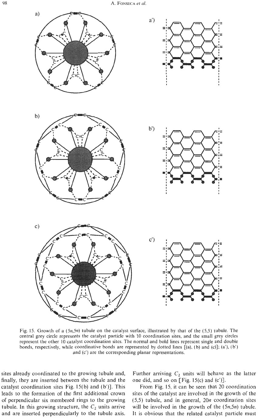
Fig. 15. Growth of a (5n,5n) tubule on the catalyst surface, illustrated by that of the (5,5) tubule. The
central grey circle represents the catalyst particle with
10
coordination sites, and the small grey circles
represent the other
10
catalyst coordination sites. The normal and bold lines represent single and double
bonds, respectively, while coordinative bonds are represented by dotted lines [(a), (b) and (c)]; (a'),
(b)
and (c') are the corresponding planar representations.
sites already coordinated to the growing tubule and,
finally, they are inserted between the tubule and the
catalyst coordination sites Fig. 15(b) and (b)]. This
leads to the formation
of
the first additional crown
of perpendicular six membered rings to the growing
tubule. In this growing structure, the
C2
units arrive
and are inserted perpendicularly to the tubule axis.
Further arriving
C2
units will behave as the latter
one did, and
so
on [Fig. 15(c) and (c')].
From Fig. 15, it can be seen that
20
coordination
sites
of
the catalyst are involved in the growth
of
the
(5,5) tubule, and in general,
20n
coordination sites
will be involved in the growth
of
the (5454 tubule.
It is obvious that the related catalyst particle must
Graphitizable coiled carbon nanotubes
99
have more than the
20
coordination sites used, at
least for the decomposition of acetylene.
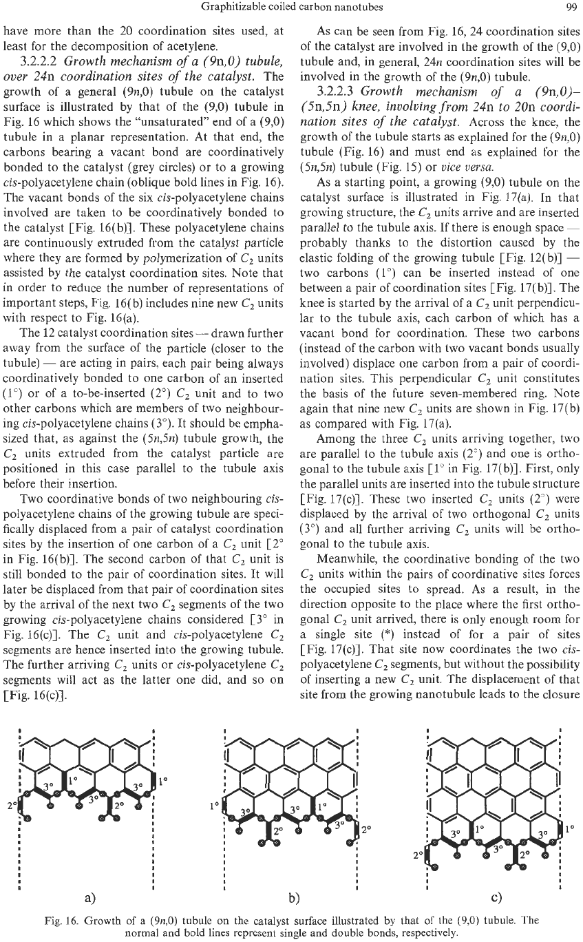
3.2.2.2
Growth mechanism
of
a
(9n,0)
tubule,
over
24n
coordination sites
of
the catalyst.
The
growth of
a
general
(9n,O)
tubule on the catalyst
surface is illustrated by that of the
(9,O)
tubule in
Fig. 16 which shows the "unsaturated" end of
a
(9,O)
tubule in a planar representation. At that end, the
carbons bearing
a
vacant bond are coordinatively
bonded to the catalyst (grey circles)
or
to
a
growing
cis-polyacetylene chain (oblique bold lines in Fig. 16).
The vacant bonds of the six cis-polyacetylene chains
involved are taken to be coordinatively bonded to
the catalyst [Fig. 16( b)]. These polyacetylene chains
are continuously extruded from the catalyst particle
where they are formed by polymerization of
C2
units
assisted by the catalyst coordination sites. Note that
in order to reduce the number of representations of
important steps, Fig. 16(b) includes nine new
C2
units
with respect
to
Fig. 16(a).
The
12
catalyst coordination sites
-
drawn further
away from the surface of the particle (closer to the
tubule)
-
are acting in pairs, each pair being always
coordinatively bonded to one carbon of an inserted
(1")
or of a to-be-inserted
(2")
C,
unit and to two
other carbons which are members of two neighbour-
ing cis-polyacetylene chains
(3").
It should be empha-
sized that, as against the
(5n,5n)
tubule growth, the
C,
units extruded from the catalyst particle are
positioned in this case parallel to the tubule axis
before their jnsertion.
Two coordinative bonds of two neighbouring cis-
polyacetylene chains of the growing tubule are speci-
fically displaced from a pair of catalyst coordination
sites by the insertion of one carbon of a
C2
unit
[2"
in Fig. 16(b)]. The second carbon of that
C,
unit is
still1 bonded to the pair
of
coordination sites. It will
later be displaced from that pair
of
coordination sites
by the srrival of the next two
C,
segments
of
the two
growing cis-polyacetylene chains considered
[
3"
in
Fig. 16(c)]. The
C,
unit and cis-polyacetylene
C2
segments are hence inserted into the growing tubule.
The further arriving
C,
units or cis-polyacetylene
C2
segments will act as the latter one did, and
so
on
[Fig. 16(c)].
I
I
1
I
I
I
I
I
I
I
t
I
I
I
I
As
can be seen from Fig. 16,
24
coordination sites
of the catalyst are involved in the growth
of
the
(9,O)
tubule
and,
in general,
24n
coordination sites will be
involved in the growth of the
(9n,0)
tubule.
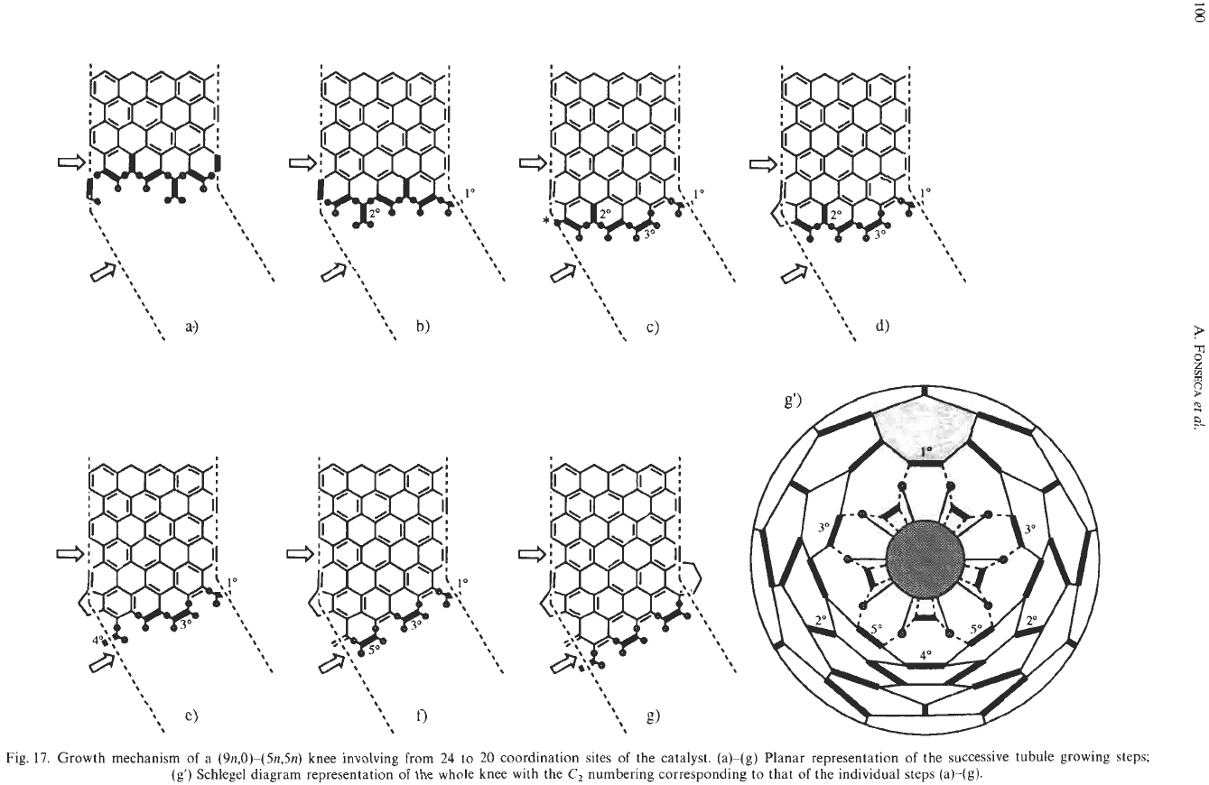
3.2.2.3
Growth mechanism
of
a
(9n,0)-
(5n,5n)
knee, involtiing
from
,7411
to
20n
coordi-
nation sites
of
the
catalyst.
Across the knee, the
growth of the tubule starts as explained for the
(9n,0)
tubule (Fig. 16) and
must
end as explained for the
(5n,5n)
tubule (Fig. 15)
or
eice versa.
As
a
starting point,
a
growing
(9,O)
tubule on the
catalyst surface is illustrated in Fig. 17(a). In that
growing structure, the
C,
units arrive and are inserted
parallel to the tubule axis.
If
there
is
enough space
~
probably thanks to the distortion caused by the
elastic folding of the growing tubule
[Fig.
12(b)]
-
two carbons
(1")
can be inserted instead of one
between a pair of coordination sites [Fig. 17(b)]. The
knee is started by the arrival of a
C,
unit perpendicu-
lar to the tubule axis, each carbon
of
which has a
vacant bond for coordination. These
two
carbons
(instead of the carbon with two vacant bonds
usually
involved) displace one carbon from a pair
of
coordi-
nation sites. This perpendicular
C,
unit constitutes
the basis of the future seven-membered ring. Note
again that nine new
C,
units are shown in Fig. 17(b)
as compared with Fig. 17(a).
Among the three
C,
units arriving together, two
are parallel to the tubule axis
(2')
and one
is
ortho-
gonal to the tubule axis
[I"
in Fig. 17(b)]. First,
only
the parallel units are inserted into the tubule structure
[Fig. 17(c)]. These two inserted
C,
units
(2')
were
displaced by the arrival of two orthogonal
C,
units
(3")
and all further arriving
C,
units will be ortho-
gonal to the tubule axis.
Meanwhile, the coordinative bonding of the two
C2
units within the pairs of coordinative
sites
forces
the occupied sites to spread.
As
a
result, in the
direction opposite to the place where the first ortho-
gonal
C,
unit arrived, there is only enough room for
a
single site
(")
instead of for a pair of sites
[Fig. 17(c)]. That site now coordinates the two cis-
polyacetylene
C,
segments, but without the possibility
of inserting a new
C,
unit. The displacement of that
site from the growing nanotubule leads to the closure
10
Fig.
16. Growth of a
(9n,O)
tubule on the catalyst surface illustrated by that
of
the
(9,O)
tubule. The
normal and bold lines represent single and double bonds, respectively.
I I
.
10
.
.1
.
*
.
.
.
8
.
8
*.
.
8.
8
.
.
.
,
*
.
.
8
.
,
8
8
'L
.
'8.
e>
8
.
.
.
.
.
,
.
.
.
.
.
Fig.
17.
Growth mechanism of a
(9n,0)-(5n,5n)
knee
involving from
24
to
20
coordination sites
of
the catalyst. (a)-(g) Planar representation of the successive tubule growing steps;
(g') Schlegel diagram representation of the whole knee with the
C,
numbering corresponding to that of the individual steps (a)-(g).
Graphitizable
coiled
carbon nanotubes
101
of
the five-membered ring [Fig. 17(d)]. Note also
that only six new
C,
units are shown in Fig. 17(c)
with
respect to Fig. 17(b).
Once the pair of sites is disconnected from the
growing tubule [Fig. 17(d)], an orthogonal
C2
unit
is
inserted below the five membered ring
[4"
in
Fig. 17(e)]. The latter inserted
C2
unit and the remain-
ing two cis-polyacetylene
C2
segments are finally
displaced by the arrival two orthogonal
C2
units
[Y
in Fig. 18(f)].
The carbon atoms linked to the remaining twenty
coordination sites have now finished to rearrange to
a
fivefold symmetry [Fig. 17(f)]. Consecutive inser-
tion of the five orthogonal
C2
units
[lo,
3"
and
5")
displaced from the catalyst by the arrival of five new
Orthogonal
C,
units closes the seven-membered ring
and completes the knee [Fig. 17(g) and (g')]. Further
growth will yield a (5n,5n) tubule. It will proceed
as already explained in Fig.
15.
Figure 17(g') is
a
Schlegel diagram explanation of the (9,O)-(
5,5)
knee,
equivalent
to
Fig. 17(g). In that diagram
it
is possible
to identify the
C,
units introduced at the different
steps [Fig. 17(a)-(g)] by their numbering.
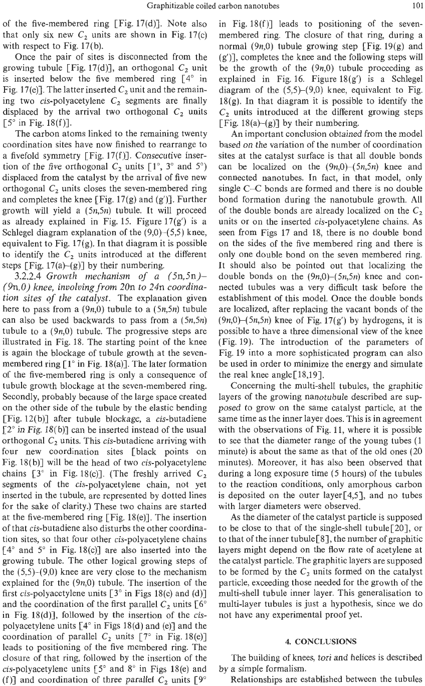
3.2.2.4
Growth
mechanism
of
a
(5n,5n)-
(9~0)
knee,
involving
from
20n
to
24n
coordina-
tion
sites
of
the
catalyst.
The explanation given
here to pass from
a
(9n,0) tubule to
a
(5n,5n)
tubule
can also be used backwards to pass from a (5n,5n)
tubule to a (9n,O) tubule. The progressive steps are
illustrated in Fig.
18.
The starting point of the knee
is again the blockage
of
tubule growth
at
the seven-
membered ring
[
1"
in
Fig. lX(a)J. The later formation
of
the five-membered ring is only
a
consequence of
tubule growth blockage at the seven-membered ring.
Secondly, probably because of the large space created
on
the other side of the tubule by the elastic bending
[Fig. 12(b)] after tubule blockage,
a
cis-butadiene
[2" in Fig. 18(b)] can be inserted instead
of
the usual
orthogonal
6,
units. This cis-butadiene arriving with
four new coordination sites [black points on
Fig. 18(b)] will be the head of
two
cis-polyacetylene
chains
C3"
in
Fig. 18(c)]. (The freshly arrived
C,
segments
of
the cis-polyacetylene chain, not yet
inserted in the tubule, are represented by dotted lines
for the sake of clarity.) These two chains are started
at the five-membered ring [Fig. 18(e)]. The insertion
of
that cis-butadiene also disturbs the other coordina-
tion sites,
so
that
four other cis-polyacetylene chains
[4" and
5"
in Fig. 18(c)] are also inserted into the
growing tubule. The other logical growing steps
of
the (53-(9,O) knee are very close to the mechanism
explained for the
(9n,0)
tubule. The insertion of the
first cis-polyacetylene units
[3"
in
Figs 18(c) and (d)]
and the coordination of the first parallel
C2
units
[6"
in Fig. 18(d)], followed by the insertion
of
the cis-
polyacetylene units [4O in Figs 18(d) and (e)] and the
coordination of parallel
C2
units
[7"
in Fig. 18(e)]
leads to positioning of the five membered ring. The
closure of that ring, followed by the insertion of the
cis-polyacetylene units
[5"
and
8"
in Figs 18(e) and
in Fig. 18(f)] leads to positioning of the seven-
membered ring. The closure of that ring, during
a
normal (9n,O) tubule growing step [Fig. 19(g) and
(g')], completes the knee and the following steps will
be the growth of the
(9n,O)
tubule proceeding as
explained in Fig.
16.
Figure 18(g') is a Schlegel
diagram of the (5,5)-(9,O) knee, equivalent to Fig.
18(g). In that diagram
it
is
possible to identify the
C,
units introduced at the different growing steps
[Fig. lS(a)-(g)] by their numbering.
An
important conclusion obtained from the model
based
on
the variation of the number of coordination
sites at the catalyst surface is that all double bonds
can be localized on the (9n,0)-(5n,5n) knee and
connected nanotubes.
In
fact, in that model, only
single C-C bonds are formed and there
is
no double
bond formation during the nanotubule growth.
All
of the double bonds are already localized on the
C,
units or on the inserted cis-polyacetylene chains.
As
seen from Figs 17 and 18, there is no double bond
on the sides
of
the five membered ring and there is
only one double bond
on
the seven membered ring.
It should also be pointed out that localizing the
double bonds on the (9n,0)-(5n,5n) knee and con-
nected tubules was
a
very difficult task before the
establishment of this model. Once the double bonds
are localized, after replacing the vacant bonds of the
(9n,0)-(
5n,5n)
knee of Fig. 17(g') by hydrogens,
it
is
possible to have a three dimensional view
of
the knee
(Fig. 19). The introduction of the parameters of
Fig. 19 into
a
more sophisticated program can also
be used in order to minimize the energy and simulate
the real knee angle[18,19].
Concerning the multi-shell tubules, the graphitic
layers
of
the growing nanotubule described are sup-
posed to grow on the same catalyst particle, at the
same time
as
the inner layer does. This
is
in agreement
with the observations of Fig.
11,
where it is possible
to see that the diameter range of the young tubes
(1
minute) is about the same as that of the
old
ones
(20
minutes). Moreover, it has also been observed that
during
a
long exposure time (5 hours) of the tubules
to the reaction conditions, only amorphous carbon
is deposited on the outer layer[4,5], and no tubes
with larger diameters were observed.
As
the diameter of the catalyst particle is supposed
to be close to that of the single-shell tubule[20], or
to that of the inner tubule[8], the number of graphitic
layers might depend on the flow rate
of
acetylene at
the catalyst particle. The graphitic layers are supposed
to be formed by the
Cz
units formed
on
the catalyst
particle, exceeding those needed for the growth of the
multi-shell tubule inner layer. This generalisation
to
multi-layer tubules
is
just a hypothesis, since we do
not have any experimental proof yet.
4.
CONCLUSIONS
The building of knees, tori
and
helices
is
described
bv
a
simple formalism.
(f)] and coordination
of
three parallel
C,
units
[So
Relationships are established between the tubules

I
ei
.
'
I
I
I
I
.
,
t
I
I
I
I
I
I
I
I
I
.i
\-
.
.
.
,
I
I
*
I
I
I
I
I
I
I
I
I
I
I
I
I
0
*
i*
.
?
E
F
Fig. 18. Growth mechanism of
a
(5n,5n)-(9n,O)
knee involving from
20
to
24
coordination sites of the catalyst. (a)-(g) Planar representation
of
the successive tubule growing steps;
(g') Schlegel diagram representation
of
the whole knee with the
C2
numbering corresponding to that
of
the individual steps (a)-(g).
Graphitizable coiled carbon nanotubes
103
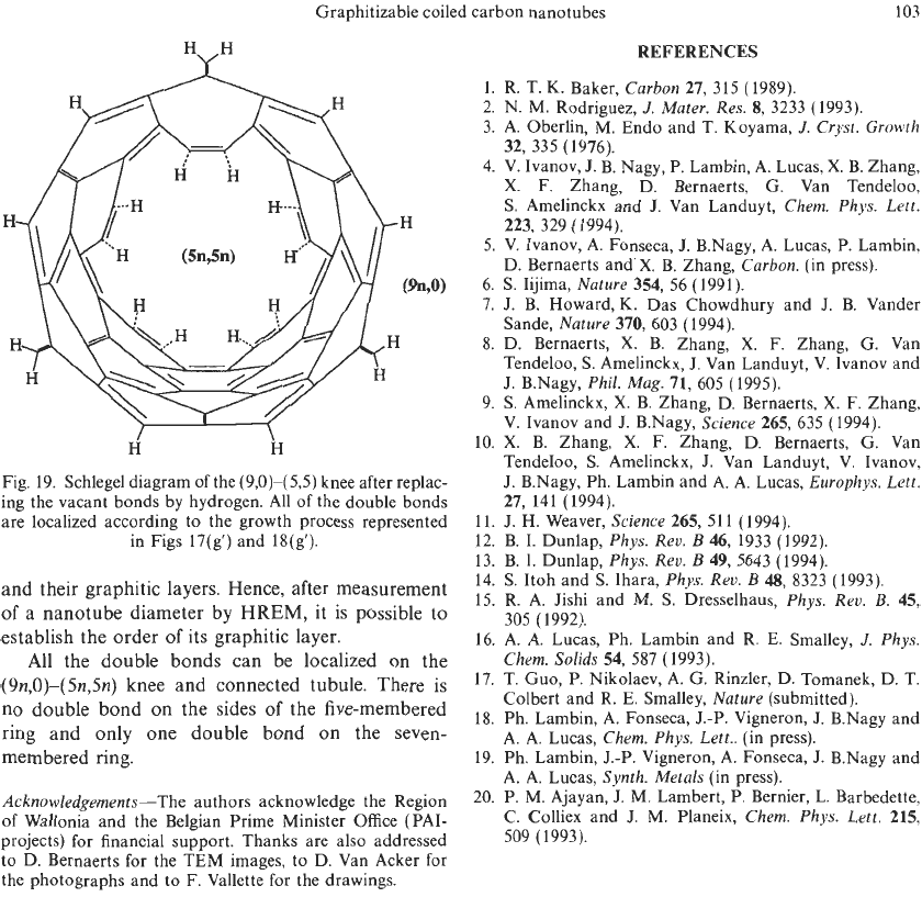
HH
v
H
(5ninJn)
H’
H
H
Fig.
19.
Schlegel diagram of the
(9,O)-(5,5)
knee after replac-
ing the vacant bonds by hydrogen. All of the double bonds
are localized according to the growth process represented
in Figs
17(g’)
and
18(g’).
and their graphitic layers. Hence, after measurement
of a nanotube diameter by HREM, it is possible to
establish the order
of
its graphitic layer.
All the double bonds can be localized
on
the
(9n,0)-(
5n,5n)
knee and connected tubule. There
is
no double bond
on
the sides
of
the five-membered
ring and only one double bond on the seven-
membered ring.
Acknowledgements-The
authors acknowledge the Region
of Wallonia and the Belgian Prime Minister Office (PAI-
projects) for financial support. Thanks are also addressed
to D. Bernaerts for the
TEM
images, to D. Van Acker for
the photographs and to
F.
Vallette for the drawings.
REFERENCES
1.
R.
T.
K.
Baker,
Carbon
27,
315 (1989).
2.
N.
M.
Rodriguez,
J.
Mater. Res.
8,
3233 (1993).
3.
A. Oberlin, M. Endo and T. Koyama,
J.
Cryst. Growth
32,
335 (1976).
4.
V. Ivanov, J. B. Nagy, P. Lambin, A. Lucas,
X.
B. Zhang,
X.
F. Zhang, D. Bernaerts,
G.
Van Tendeloo,
S.
Amelinckx and J. Van Landuyt,
Chem. Phys. Lett.
223,
329 (1994).
5.
V. Ivanov, A. Fonseca,
J.
B.Nagy, A. Lucas, P. Lambin,
D. Bernaerts and
X.
B. Zhang,
Carbon.
(in press).
6.
S.
Iijima,
Nature
354,
56 (1991).
7.
J. B. Howard,K. Das Chowdhury and J. B. Vander
Sande,
Nature
370,
603 (1994).
8.
D. Bernaerts,
X.
B. Zhang,
X.
F.
Zhang, G. Van
Tendeloo,
S.
Amelinckx, J. Van Landuyt, V. Ivanov and
J. B.Nagy,
Phil. Mag.
71,
605 (1995).
9.
S.
Amelinckx,
X.
B. Zhang, D. Bernaerts,
X.
F. Zhang,
V. Ivanov and J. B.Nagy,
Science
265,
635 (1994).
10.
X.
B. Zhang,
X.
F.
Zhang, D. Bernaerts,
G.
Van
Tendeloo,
S.
Amelinckx, J. Van Landuyt, V. Ivanov,
J. B.Nagy, Ph. Lambin and A. A. Lucas,
Europhys.
Lett.
27,
141 (1994).
11.
J. H. Weaver,
Science
265,
511 (1994).
12.
B. I. Dunlap,
Phys. Rev.
B
46,
1933 (1992).
13.
B. I. Dunlap,
Phys. Rev.
B
49,
5643 (1994).
14.
S.
Itoh and
S.
Ihara,
Phys. Rev.
B
48,
8323 (1993).
15.
R. A. Jishi and M.
S.
Dresselhaus,
Phys.
Rev.
B.
45,
305 (1992).
16.
A. A. Lucas, Ph. Lambin and R. E. Smalley,
J.
Phys.
Chem. Solids
54,
587 (1993).
17.
T. Guo, P. Nikolaev, A.
G.
Rinzler, D. Tomanek, D.
T.
Colbert and R.
E.
Smalley,
Nature
(submitted).
18.
Ph. Lambin, A. Fonseca, J.-P. Vigneron, J. B.Nagy and
A. A. Lucas,
Chem. Phys. Lett..
(in press).
19.
Ph. Lambin, J.-P. Vigneron, A. Fonseca, J. B.Nagy and
A. A. Lucas,
Synth.
Metals
(in press).
20.
P.
M.
Ajayan, J.
M.
Lambert,
P.
Bernier, L. Barbedette,
C. Colliex and J.
M.
Planeix,
Chem. Phys. Lett.
215,
509 (1993).
HEMI-TOROIDAL NETWORKS
IN
PYROLYTIC
CARBON NANOTUBES
A.
SARKAR,
H.
W.
KROTO
School
of
Chemistry and Molecular Science, University
of
Sussex, Brighton, BN1
9QJ
U.K.
and
M.
ENDO
Department
of
Engineering, Shinshu University, Nagano, Japan
(Received
26
May
1994;
accepted
in
revised
form
16
August
1994)
Abstract-Evidence for the formation
of
an archetypal hemi-toroidal link structure between adjacent
concentric walls in pyrolytic carbon nanotubes is presented. The observed and simulated TEM images for
such structures are in excellent agreement. This study suggests that double-walled carbon nanotubes,
in
which the inner and outer tubes are linked by such hemi-toroidal seals, may be one viable way
of
over-
coming the reactivity at the graphene edges
of
open-ended tubes
to
engineer stable and useful graphene
nanostructures.
Key
Words-Nanotubes, pyrolytic carbon nanotubes, hemi-toroidal nanostructures.
1.
INTRODUCTION
The discovery by Iijima[ 11 that carbon nanotubes
form in a Kratschmer-Huffman fullerene generator[2],
and the subsequent development
of
techniques by
Ebbeson and Ajayan[3] and others to produce them
in viable quantities, promise to have important impli-
cations for future nanotechnology. The tubes are es-
sentially elongated fuIlerenes[4] and, thus, description
(in particular structural characterisation) in terms of
fullerene chemistry/physics principles is appropriate
and useful.
A
growth mechanism has been proposed
for the primary tube growth phase[4] which involves
ingestion
of
carbon fragments (e.g., atoms and chain
molecules)
at
the reactive hemi-fuuerene closed end-
caps
of
the tubes. An open-ended growth mechanism
has
also
been proposed[5].
A
closed-end growth mech-
anism is consistent with the--observations
of
Ulmer
et
al.
[6] and McElvany
et
al.
[7], that fullerenes can
grow by ingestion of carbon fragments into their com-
pletely closed networks. Both growth schemes also are
consistent with Iijima's observation that, in general,
the tubes appear
to
have their hexagons helically dis-
posed in the tube walIs[l].
The discovery that carbon generates closed-cage
fullerenes spontaneousIy[2,8]
as
well as nanotubes[l,3]
has
stimulated the question of whether other topolog-
ically accessible networks are feasible. Predictions
on
the possibility
of
both small fullerenes[9] and giant ful-
lerenes[lQ,ll] appear to have been vindicated[l2,13].
As
well as general closed-cage structures, extended
repeat-pattern networks involving seven- and other-
membered rings have been considered by Terrones and
MacKay[l4,l5] and Lenosky
et
al.1161.
Other struc-
tures have been considered and,
in
particular, Cher-
nozatonskii[l.7] and Ihara
et
a1.[18,19] have discussed
toroidal structure.
During the course
of
a
detailed study of the struc-
ture and growth of pyrolytic carbon nanotubes
(F'CNTs)
we have found that complex graphitisation processes
occur during
a
second
stage
of
heat treatment
of
these
materials[20,21]. In particular, we here draw attention
to evidence that hemi-toroidal graphite surfaces occur
regularly during nanotube production.
In
this commu-
nication we present evidence for the formation of
single-
layered hemi-toroid structures, within bulk multi-walled
material during PCNT graphitisation. The structures
occur in material prepared by pyrolysis
of
hydrocar-
bons at ca. 1000°C and subjected
to
secondary heat
treatment at 2800°C. The structures have been studied
experimentally by high resolution transmission electror,
microscopy (HRTEM)[20] and the resulting images
compared with simulations. The simulated structures
were generated from hypothetica1 fullerene related
hemi-toroidal networks, which were constructed on
the basis of feasible graphene topologies relaxed by
molecular mechanics. During the course
of
the present
study
of
PCNTs, Iijima
et
al.
[5]
have obtained TEM
images showing related structures
in
arc-formed car-
bon nanotubes
(ACNTs).
2.
OBSERVATIONS
The PCNTs obtained by decomposition
of
benzene
at
ca.
1000-1070°C
on
a
ceramic substrate were gath-
ered using
a
toothpick and heat treated at
a
tempera-
ture of
2800°C
for
15
minutes[21]. The heat-treated
PCNTs were then mounted on a porous amorphous
carbon electron microscope grid (so-called carbon
ultra-microgrid). HRTEM observations were made
using a LaB6 filament operating at an accelerating
voltage of 300 kV. The special aberration coefficient
C,
=
2.0 mm and lambda
=
0.0197
A.
The under-focus
105
106
A.
SARKAR
et
al.
value was chosen deltaf
=
65
nm, where the sin(x)
transfer function has a large plateau at sin(x) ca. -1
against the interlayer spacing of carbon in the range
5.0-2.8 A. These conditions were optimum for observ-
ing high-contrast
002
lattice fringes form the PCNTs.
The simulations were carried out on a Silicon
Graphics Iris Indigo workstation using the CERIUS
molecular modeling and the associated HRTEM mod-
ule. The multislice simulation technique was applied
using the following parameters: electron energy
400
kV
(lambda
=
0.016 A); C, (aberration coefficient)
=
2.7 mm; focus value deltaf
=
66 nm; beam spread
=
0.30
mrad.
In Fig. 1 is shown a HRTEM image of part of
the end
of
a PCNT. The initial material consisted of
carbon nanotubes upon which bi-conical spindle-like
secondary growth had deposited[21], apparently by in-
homogeneous deposition of aromatic carbonaceous,
presumably disordered, layers on the primary substrate
nanotube. Prior to further heat treatment, the second-
Fig.
1.
The sealed-off tip of an annealed PCNT
ary growth showed no regular structure in the HRTEM
images (Fig.
l),
suggesting that it might consist largely
of
some form of “amorphous” carbon. After the sec-
ond stage of heat treatment, at 28OO0C, the amor-
phous sheaths graphitise to a very large degree,
producing multi-walled graphite nanotubes which tend
to be sealed off at points where the spindle-like for-
mations are thinnest. The sealed-off end region of one
such PCNT is shown in Fig.
1.
The detailed analysis of the way in which the over-
all and internal structure of PCNTs apparently arise
is discussed elsewhere[20]. Here, we draw attention to
some particularly interesting and unusual structures
which occur in the body of the nanotubes. An expan-
sion of the section of the central core which lies ca.
f
below the tip
of
the nanotube in Fig.
1
is shown in
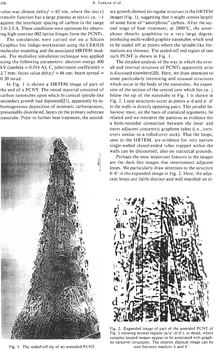
Fig. 2. Loop structures occur at points a-d and a‘-d‘
in the walls in directly opposing pairs. This parallel be-
haviour must,
on
the basis
of
statistical arguments, be
related and we interpret the patterns as evidence for
a hemi-toroidal connection between the inner and
outer adjacent concentric graphene tubes (Le., turn-
overs similar to a rolled-over sock). That the loops,
seen in the HRTEM, are evidence for very narrow
single-walled closed-ended tubes trapped within the
walls can be discounted, also on statistical grounds.
Perhaps the most important features in the images
are the dark line images that interconnect adjacent
loops. We particularly draw attention to the structure
b-b‘ in the expanded image in Fig. 2. Here, the adja-
cent loops are fairly distinct and well matched on ei-
Fig.
2.
Expanded image
of
part
of
the annealed PCNT
of
Fig.
1
showing several regions (a/a’-d/d‘), in detail, where
complex looped images appear
to
be associated with graph-
ite turnover structures. The clearest eliptical image can be
seen between markers b and b’.
Hemi-toroidal networks in pyrolytic carbon nanotubes
107
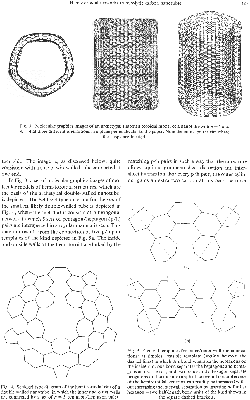
Fig.
3.
Molecular graphics images of an archetypal flattened toroidal model
of
a nanotube with
n
=
5
and
m
=
4
at three different orientations
in
a
plane perpendicular to the paper. Note the points
on
the rim where
the cusps are located.
ther side. The image
is,
as discussed below, quite
consistent with
a
single twin-walled tube connected at
one end.
In Fig.
3,
a set
of
molecular graphics images
of
mo-
lecular models
of
hemi-toroidal structures, which are
the basis
of
the archetypal double-walled nanotube,
is depicted. The Schlegel-type diagram for the
rim
of
the smallest likely double-walled tube is depicted in
Fig.
4,
where the fact that it consists
of
a
hexagonal
network in which
5
sets
of
pentagodheptagon (p/h)
pairs are interspersed in a regular manner is seen. This
diagram results from the connection
of
five p/h pair
templates
of
the kind depicted in Fig. 5a. The inside
and outside walls
of
the hemi-toroid are linked by the
matching p/h pairs in such a way that the curvature
allows optimal graphene sheet distortion and inter-
sheet interaction. For every p/h pair, the outer cylin-
der gains an extra two carbon atoms over the inner
g[-1g
\
\
I I I
I
I
\
I-
\
L
I
A
\
I
\
i
\
/
/
\
i
(b)
Fig.
5.
General templates for inner/outer wall rim connec-
tions: a) simplest feasible template (section between the
dashed lines) in which
one
bond separates the heptagons
on
the inside rim,
one
bond separates the heptagons and penta-
gons across the rim, and two bonds and a hexagon separate
pengatons
on
the outside rim; b) The overall circumference
of the hemitoroidal structure can readily be increased with-
out increasing
the
interwall separation
by
inserting
rn
further
hexagon
+
two half-length bond units
of
the kind shown in
the square dashed brackets.
Fig.
4.
Schlegel-type diagram
of
the hemi-toroidal rim of
a
double walled nanotube, in which the inner and outer walls
are connected by a set
of
n
=
5
pentagon/heptagon pairs.