Ellis,J. Pressure transients in water engineering, A guide to analysis and interpretation of behaviour
Подождите немного. Документ загружается.

16.5 Air valve operation
To illustrate the possible influence which discharge conditions may
have upon the upstream pipeline, a sewage pumping system containing
air valves is considered. The sewage transmission system of Sharjah
Main Drainage Pumping Station No. 1 uses parallel DN 450 and DN
700 pumping mains to convey sewage a distance of over 6 km, with
the mains discharging to a modest chamber from which flows enter a
gravity sewer. Air valves were included at around chainage 4.4 km on
each main. While the exit level into the gravity sewer from the dis-
charge chamber was above the air valves’ elevation, the base of the
chamber where the rising mains enter the chamber was below the air
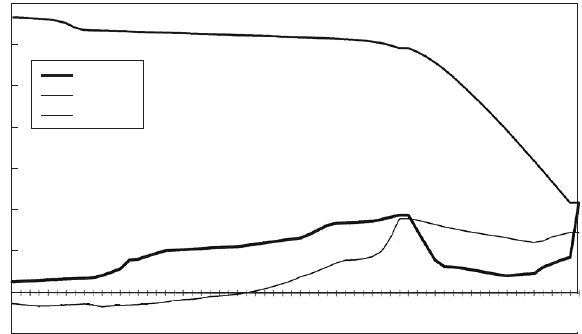
valves. Figure 16.12 shows envelope curves along one of the mains
for a combined pump start/trip analysis with most of the system up
until the air valves’ site subject to vacuum pressures after trip. Maxi-
mum pressures during start-up were based upon the assumption that
the pipelines were entirely primed. Downstream of the air valves,
minimum pressures remained positive.
On flow reversal at the discharge end of the system, the chamber
empties and head falls to the extent that hydraulic levels at the down-
stream chamber are less than at the air valves’ location. This means that
the air which has been admitted to the pipelines through the air valves
cannot entirely be purged from the system during reversed flow. Some
air will remain in the pipeline when pumps are restarted and this will
alter the start-up transient analysis.
292
il (mASL)
h
max
h
min
Chaina
g
e (m)
Elevation (mASL)
35
30
25
20
15
10
5
0
–5
301.5
603.0
904.5
1206.0
1507.5
1809.0
2110.5
2411.9
2713.4
3014.9
3316.4
3617.9
3919.4
4220.9
4422.3
4725.2
5028.0
5330.8
5633.6
5936.4
6144.9
Fig. 16.12. Envelope curves for sewage rising main with air valves
Pressure transients in water engineering
There is also the question of alleviating the severe vacuum pressure
conditions which were found to occur after pump trip, between the
pumping station and the air valves. A pressure vessel was included
at the pumping station for this purpose. With the vessel in place,
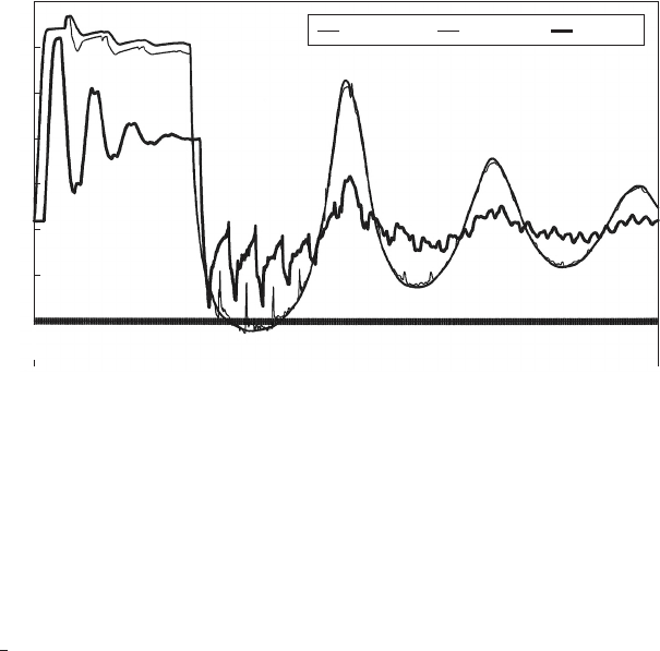
Fig. 16.13 shows head variations after two pumps were started in
sequence with 30 s between each pump being operated. After around
2
1
2
min. essentially steady flow had been achieved and the pumps
were tripped together. Pump start still produces the maximum system
pressure and air valves continue to operate as before. Head variations
at the pumping station, at the start of the DN 450 main and at the
mid-point of this main, are shown in this figure. When flow reverses,
the discharge chamber at the downstream end of the system supplies
liquid to remove air which had entered through the air valves. The
air valves in turn were used to allow water to flow to the pumping
station to recharge the pressure vessel. The end result is that the final
system head is relatively low as the discharge chamber is almost emptied
and the air valves remain open with air pockets in each pipeline.
16.6 Summary of influence of discharge arrangements
Generally speaking, head conditions at the downstream end of a system
will not significantly influence the initial rarefaction pressure wave in a
rising main after a pumping failure. At later stages, especially after flow
reversal has occurred, the configuration at the discharge end of a
293
Time (s)
Head (mASL)
35
30
25
20
15
10
5
0
–5
d/s vessel Start 450 Mid 450
0.276
19.596
38.916
58.236
77.556
96.876
116.196
135.516
154.836
174.156
193.477
212.797
232.117
251.437
270.757
290.077
309.397
328.717
348.037
367.357
386.677
405.997
425.317
444.637
463.957
483.278
502.598
521.918
541.238
560.558
579.878
599.198
Fig. 16.13. Head variation for combined pump start/trip analysis
Discharge conditions
network may start to influence events. If flow reversal at the outfall
produces a decrease in piezometric level at this point, the strength of
a compression wave travelling upstream and subsequent upsurge pres-
sures at a pumping station can be significantly affected. The refilling
time of vessels will be more prolonged and filling may be incomplete.
If air valves have operated during the initial fall in head after pump
trip, the time of air venting will be increased by any fall in downstream
head at the outfall. It is even possible for downstream head to decline to
the point at which air expulsion can no longer take place. This creates a
situation in which it is restarting of pumps which will finally purge any
remaining air from the system. Pumps may also be restarting against a
reduced static head as a consequence of the lowering of downstream
piezometric level.
Detailed consideration of discharge conditions may be especially
important when making comparisons between prediction and field
observation. Timings of events and extremes of head and flow may be
significantly affected by variations of piezometric level at the down-
stream end of a pipeline.
294
Pressure transients in water engineering
17
Air valves
Alleviation of sub-atmospheric transient pipeline pressures commonly
requires the introduction of an additional supply of fluid. From a cost
point of view, it is an attractive option to use pipeline fittings which
are already present for other purposes to achieve this result. The air
valve presents this opportunity. The usefulness of these valves in
assisting to alleviate surging action comes from their ability to admit
substantial quantities of air when piezometric level falls below the air
valve elevation. Following a pumping failure for instance, as discharge
from pumps decreases, the air inflow augments the diminishing flow
from the pumping station so that downstream of the air valve, flow
deceleration is not as great as that upstream of the valve. This reduced
deceleration implies that subsequent head changes will be correspond-
ingly lower, thus alleviating minimum pressure conditions.
These valves are commonly installed along a pipeline in an arrange-
ment intended primarily to allow easy emptying and filling of the pipeline
during maintenance and in the case of double-orifice valves (DOVs) to
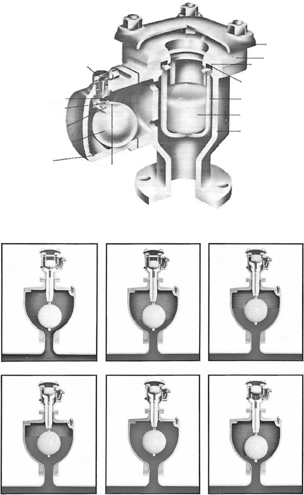
facilitate venting of pressurised pockets of air. Figure 17.1 illustrates the
main components of an ‘APEX’ DOV manufactured by Glenfield Valves
Ltd. The valve has an orifice at the top which allows for large air flows
through the valve with a modest head drop. Flow ceases when the
float rises to seal against the orifice. A second much smaller orifice
with a lever attached is used to control outflow of air under pressure.
The smaller orifice is adjustable. Usually these valves are of a self-
acting pattern and so may also operate to admit air during a transient
event if piezometric level at the valve falls below the operating elevation
of the air valve. If this occurs, air will enter the pipeline, producing a
discontinuity in flow past the air valve connection. Figure 17.2 illustrates
the sequence of operation of an air valve.
295
296
Body
Float
Float guide
Seal ring
Seat ring
Cover
Cowl
Orifice cover
Orifice bracket
Sealing face
Fulcrum pin
Float and lever
Body
Adjusting
screw
Fig. 17.1. Double-orifice air valve
1 Venting 2 Filling 3 Closure
4 Sealin
g
5 Pressurisation 6 Relievin
g
Fig. 17.2. Operating sequence of sewage air valve
Pressure transients in water engineering

17.1 Normal air valve locations
Air valves are a feature of the majority of water and sewage systems and
the distribution of these valves is largely dictated by the longitudinal
profile of each pipeline. Figure 17.3 illustrates locations in which it
may be desirable to include air valves.
(a) A double-orifice valve may be included downstream of a pumping
station to remove air which may be entrained at a pump’s suction
intake. Following pumping failure, an air valve at this location
297
DOV = double-orifice valve, SOV = sin
g
le-orifice valve
HGL
PS
DOV
SOV SOV SOV
SOV
800 m
SOV
SOV
SOV
SOV
DOV
DOV
SOV
DOV
DOV
DOV
(c)(b)(a)
(d)
(e)
(f)
800 m
(g) (h)
MM
Fig. 17.3. Typical air valve locations
Air valves
may operate to admit a substantial volume of air depending upon
operating head conditions.
(b) At a defined summit on a pipeline, entrained air may accumulate
and if not removed will eventually lead to a reduction in efficiency
of the system. A DOV will allow air to be vented under pressure
through the small orifice. After a pumping failure, if piezometric
level should fall to the valve operating level then air inflow will
occur through the large orifice. A valve at this location is important
for emptying and filling of the adjacent sections of pipeline.
(c) The locations illustrated are similar to (b) but represent a high
stretch of main, say over a plateau, and the valves serve similar
functions.
(d) This represents long stretches of main of uniform gradient. Air can
migrate along a pipeline of shallow gradient and the ability to vent
this air is useful. Typically an interval of 800 m or so might be
allowed between neighbouring valves.
(e) As for (d).
(f ) As for (d).
(g) In a gravity system an isolating valve may be provided at the
upstream end of the main. A DOV downstream of the isolating
valve is necessary for emptying and filling of the pipeline and may
also vent any air entrained at the inlet.
(h) A DOV may usefully be included at inlet to a tank or reservoir
where a valve is provided to shut off inflow. In the event of flow
reversal with the inlet valve closed, vacuum pressures would
occur in the supply pipeline, were a means of ventilating the pipe-
line not provided.
It should be noted that some pipelines may have no air valves
installed. If, in a pumping main for instance, the pipeline rises continu-
ously to the discharge point, then any air can be expected to migrate
downstream and eventually to escape through the pipe discharge. Simi-
larly, some gravity mains are devoid of air valves by virtue of their
profile. Where flow velocities are high then it may be assumed that
all air will be carried along with the flow and escape at the downstream
end of the system.
17.2 Air valves for surge alleviation
One of the attractions of air valves as a means of surge alleviation arises
from their presence along a pipeline for operational purposes. No extra
298
Pressure transients in water engineering
cost is incurred by their use in hydraulic transient suppression unless
modifications are required or possibly extra valves.
There are many instances where, knowingly or otherwise, large- or
dual-orifice air valves operate during low transient pressure conditions.
The inflow of air which occurs has the effect of preventing substantial
negative pressures from developing in the vicinity of the valve at least.
This may appear to be good practice but it is not without its dangers.
Up until the time when the piezometric level at an air valve con-
nection has fallen to the point at which the valve will operate then
the valve remains shut and has no influence upon the propagation of
the pressure wave, with flow and rates of deceleration upstream and
downstream of the valve connection being equal.
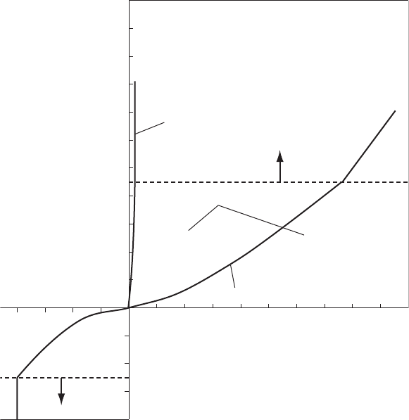
The rate of air inflow is given by the relationship between piezometric
level, valve operating level and flow rate. Suppliers should be able to
provide the necessary data, usually in the form of a chart which can
be digitised for use in a computer model. Figure 17.4 is an example of
the air inflow—outflow relationship for a large orifice and also for the
small orifice where this adjustable orifice is at its full-open setting.
The air flow rate is expressed in units of free dry air at standard tempera-
ture and pressure (STP). STP are at an ambient temperature and
atmospheric pressure. In computations it is necessary for the computer
model to take cognisance of the effect of compression/expansion of air
in the pipeline. Air volume within the pipeline at the prevailing pres-
sure may be calculated approximately using a polytropic relationship:
p
abs
Vol
n
¼ constant ð12:2aÞ
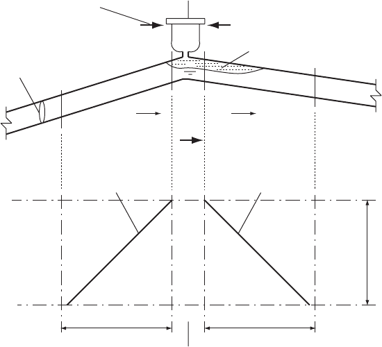
When an air valve commences operation (Fig. 17.5), writing the
equation balancing flows upstream and downstream of the valve
connection then:
V
u=s
A
u=s
þ Q
air
þ dVol
air
=dt ¼ V
d=s
A
d=s
ð17:1Þ
where Q
air
is air flow rate with inflow assumed þve. Air volumes
correspond with prevailing pressure in the pipeline at the valve connec-
tion. As upstream flow rate V
u=s
A
u=s
diminishes following a pumping
failure, the inflow of air acts to supplement this upstream flow to sustain
downstream flow rate V
d=s
A
d=s
. Thus the rate of deceleration down-
stream of the valve becomes smaller than that upstream. This reduction
in the rate of deceleration acts to suppress the pressure transient propa-
gating downstream of the air valve, with piezometric level at the valve
itself being maintained at a higher level than otherwise. This is due to
the substantial rate of air inflow which can be achieved through the
299
Air valves
large-orifice valve. Completion of the solution is accomplished using the
quasi-invariant relationships along the Cþ and C characteristics:
for the Cþ path:
Jþ¼V
u=s
þ g=aH
and for the C path:
J¼V
d=s
g=aH
The appearance of the air pocket below the valve connection acts as
an internal boundary from which strong reflection of pressure waves will
occur, much as from a reservoir, although with a variable pressure
acting on the water surface rather than a constant atmospheric pressure
as is the case with a large tank or reservoir.
Maintenance of piezometric level at the valve, at a higher level than
otherwise, will act to produce greater rates of deceleration upstream and
300
Q = flow rate (m
3
/s)
Dp = differential pressure across orifice (bar)
p = absolute pipeline pressure on outflow
and absolute atmospheric pressure on inflow
10 20 30 40 50 60 70 80 90
40 30 20 10
0.2
0.4
0.6
0.8
2.0
1.8
1.6
1.4
1.2
1.0
0.8
0.6
0.4
0.2
Inflow
Inflow
Supercritical flow
Supercritical flow
Vacuum gauge
pressure (bar)
Discharge of free dry air in STD m
3
/min
Large orifice – inflow and outflow
Outflow
Subsonic flow equations
Small orifice – outflow only
Pipeline gauge
pressure (bar)
Q = 1.02 ¥ ÷(Dpp) Q = 48 ¥ ÷(Dpp)
Fig. 17.4. Air flow characteristics of double-orifice air valve
Pressure transients in water engineering
a more rapid flow reversal in that section of main upstream of the valve.
In a pumping main where air valves have been provided, it is possible
that some of these valves will operate following a pumping failure. This
is particularly likely if no special surge protection has been included at
the pumping station to prevent this from happening. After the pumping
failure, as the negative pressure wave or downsurge propagates into the
rising main, the hydraulic gradient at an air valve may fall to the point
where the valve opens to allow inflow of air.
Where a number of air valves along a pipeline operates during the
downsurge following pumping failure then air pockets will be developed
in the pipeline below the connection to each operating valve.
Successive air valves will each act to further suppress the downsurge
so that the minimum piezometric line may appear as shown in
Fig. 17.6. For each valve which functions, deceleration of flow in the
section of line downstream of that valve is < deceleration rate upstream
of the valve connection. Suppression of the pressure transient
downstream of air valves has been achieved by providing alternative
301
Air valve
Pipe cross-section = A
Space << Dx
Dx Dx
D
t
C– characteristic
+x
C+ characteristic
V
u/s
V
d/s
Air inflow Q
air
Air pocket (Vol )
M
Fig. 17.5. Schematic of air valve operation
Air valves