Ellis,J. Pressure transients in water engineering, A guide to analysis and interpretation of behaviour
Подождите немного. Документ загружается.

272
600 mm square pipe
support block
25 mm grout
under baseplate
75 mm thick grade
C25 concrete as
blinding
900
¥
500
¥
390 mm high
value support
block
1600
¥
800 mm
¥
810 mm high pipe
support block
Visqueen D.P.M.
H. wheel
Wall thickening around
puddle pipe
300
54.600
54.300
49.430
48.129 IL
T.O.C.
54.725
2
C.L. 51.900
50.200 m
1
For details of access
platform see Record
DRG. No. 7
54.600
51.330
53.435
54.775
53.527
Fall
Soffit 54.400
Item 6
1000
49.200
48.239
T.O.C.
Fall
54.400
400
550 600 280
333
1118
2621
TWL 53.400
(See detail)
Item C
Open
Varies (45.630–48.480)
1600
¥
400 mm valve
support block
48.854
49/915
T.O.C.
D13.
D18.
D24
70
300
300
500
D14.
D11.
D15.
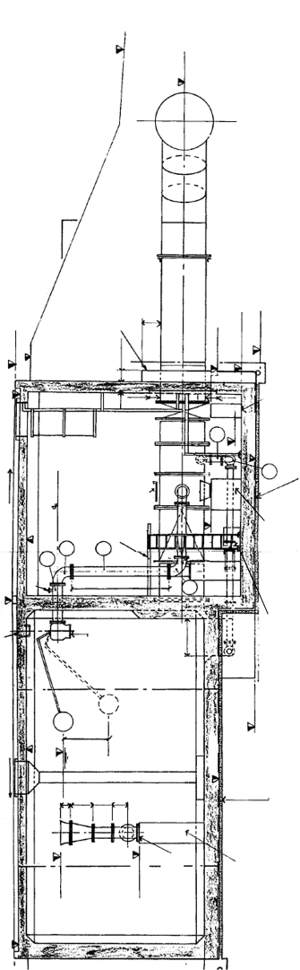
Fig. 15.11. Elevation of feeder tank
273
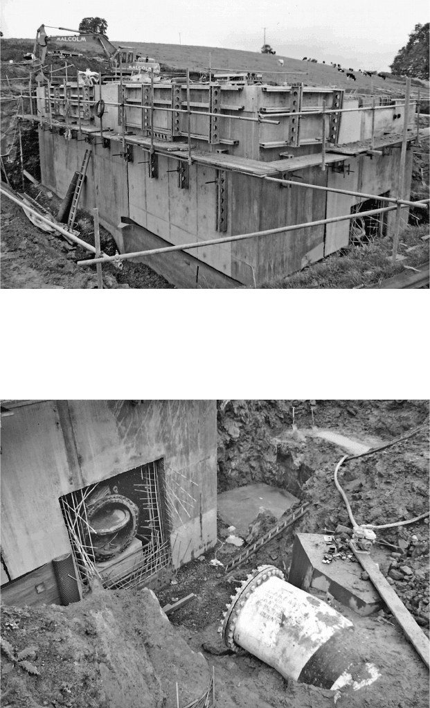
Fig. 15.12. Feeder tank chamber under construction
Fig. 15.13. Inlet to feeder tank under construction
Feeder tanks or volumetric tanks
274
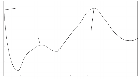
Predicted level
Observed level
Time (s)
Level (mAOD)
53.6
53.4
53.2
53.0
52.8
52.6
52.4
52.2
52.0
0.335
31.825
63.315
94.805
126.295
157.785
189.276
220.767
252.257
283.747
315.236
346.725
378.214
409.703
441.193
472.682
504.171
535.662
567.154
598.646
630.138
661.631
693.123
724.615
756.107
787.599
819.091
850.583
882.075
913.567
945.059
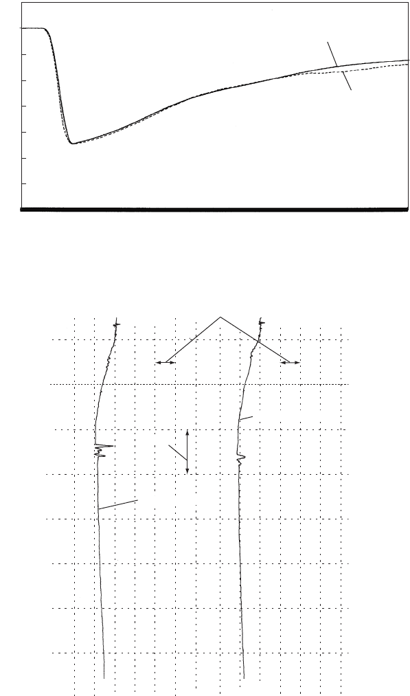
Fig. 15.14. Feeder tank water level after pump trip
1 m
Trip of two pumps
Trip of three pumps
1 min.
Fig. 15.15. Unsatisfactory feeder tank behaviour after pump trip
Pressure transients in water engineering
check valve closure occurred relatively abruptly, causing a sudden
reduction of flow into the tank as flow was then forced through the
smaller filling connection. This sudden flow deceleration would produce
additional surge effects in the pipeline.
Feeder tanks, by their nature, are located some distance from pump-
ing stations but still require regular inspection and maintenance if they
are to fulfil their function. When work is being carried out on a feeder
tank, the isolating valve will be closed and hydraulic transient investi-
gations should be carried out to establish a safe pumping rate while the
tank is out of service.
A further notable effect of the feeder tanks in this installation was to
influence the peak heads at the pumping station. Figure 15.17 shows
predicted piezometric level at the pumping station after pumps were
tripped. The first upsurge after flow reversal as the vessels refill is
quite modest. At this stage the feeder tanks are supplying water to
the vessels, and head at this end of the pipeline system is largely
275
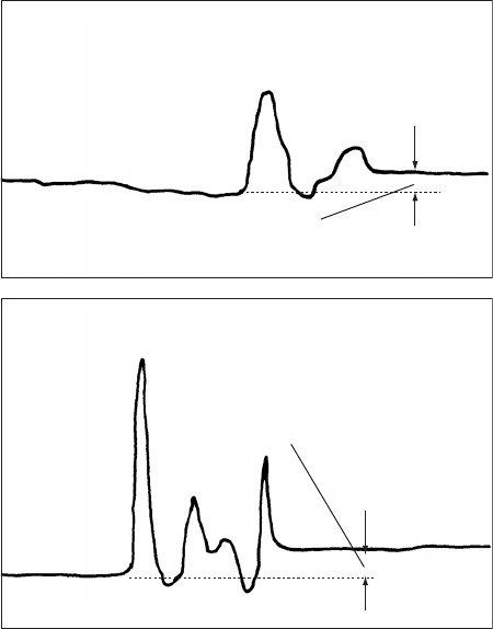
Short-term level change in feeder
before NRV closure
Short-term level change in
feeder before NRV closure
Trip of three pumps
Trip of two pumps
Fig. 15.16. Detail of feeder tank water level at commencement of refilling
Feeder tanks or volumetric tanks
controlled by the water level in the feeder and by the inertia of the
relatively short length of main between the pumping station and the
feeder tanks. During the second and much higher upsurge, the feeder
tanks are refilling and the head at their connections is much greater.
Also the inertia of the entire length of main is involved, leading to
the much greater head rise.
15.6 Aspects of feeder behaviour to consider
It is important that any simulation be of sufficient duration that the
complete picture of transient behaviour is established.
The capacity of feeder tank necessary can be quite sensitive to the
pipeline route and it may be worthwhile to consider some alternative
pipeline profiles in order to reduce the required capacity of feeder.
One of the examples discussed considered alternative alignments and
the resulting effects upon volumetric tank volume.
Refilling of the feeder is usually accomplished through reversed flow
in the pipeline system downstream of the tank although on occasion it
may be necessary to rely upon restarting of pumping to complete the
refilling process. Filling is accomplished through a smaller-diameter
connection usually fitted with a valve which closes in response to
rising water level in the tank. The check valve on the outflow connec-
tion closes as flow starts to re-enter the tank, forcing water through the
more constricted filling connection which discharges above top water
276
Second upsurge while
the feeder is re-filling
90
80
70
60
50
Elevation (mOD)
Time (min.)
1 2 3 4 5 6 7 8
Steady pumping level
First upsurge
controlled by feeder
Fig. 15.17. Head variations at pumpi ng station following pumping failure
Pressure transients in water engineering
level. Flow resistance acts to throttle inflow thus limiting magnitude of
reversed flow and assisting to prevent secondary pressure transient
effects developing when inflow ceases. The inlet valve shuts progres-
sively as tank water level rises, with flow decelerating gradually to
avoid occurrence of secondary transients. Figure 15.14 shows a record
of correct feeder tank water level behaviour during both outflow and
inflow.
Feeder tanks are usually installed at some distance from a pumping
station and not subject to daily inspection. A prolonged interval
between inspections carries the risk of malfunction. Figure 15.15
shows a recording of water level in a malfunctioning feeder tank
during outflow and inflow. Surface waves were recorded at the start
of outflow and when flow began to re-enter the tank. These waves
were the consequence of a delay in response of the outflow check valve.
15.7 Preliminary estimation of feeder tank volume
There are two aspects to establishing an initial estimate of the required
chamber volume. Continued flow into a downstream pipeline when the
feeder has come into operation will draw water from the tank. If an
upstream pumping station is equipped with a pressure vessel for
instance then this vessel will require to be refilled following the down-
surge which results from a pumping failure. Vessel refilling occurs after
flow reversal in the pipeline between the pumping station and the
feeder tank. Depending upon relative rates of deceleration of flow
within the pipelines upstream and downstream of the feeder tank,
vessel refilling may commence while the feeder is still supplying water
to the downstream pipeline or alternatively vessel refilling may not
start until flow reversal has taken place in the downstream pipeline.
In the first instance the feeder is required to supply water both to the
upstream and downstream pipelines. Vessel refilling water comes from
the feeder in this case. If flow has reversed in the downstream pipeline
before the vessel starts to refill then refilling water comes from the
downstream pipeline to some extent.
Equation (17.9a), developed for estimation of buffer tank volume,
may also be used to estimate the volume of a feeder tank.
Vol
max
=Vol
p
¼ D=ðfLÞlnf1 þ hf=zgð17:9bÞ
In this case Vol
max
is the volume of feeder tank water supplied to the
downstream pipeline and Vol
p
is volume of the downstream pipeline.
D, L and f are respectively the diameter, length and overall friction
277
Feeder tanks or volumetric tanks
factor of the downstream pipeline. The friction factor includes an
allowance for losses in the outflow connection of the feeder. hf is
the pipeline resistance loss during steady flow along the downstream
pipeline and z is the level difference between the feeder tank and the
discharge level downstream.
When it is considered necessary to include vessel refilling volume,
the equations derived in the Appendix to Chapter 12 could be used
or alternatively any of the graphical methods. As an example, equation
(A12.5a) might be used. For simplicity, this equation ignores the effect
of pipeline resistance.
Vol
m
=Vol
p
¼ V
2
o
=ð2gÞ=fzð1 h
m
=zÞþh
m
lnðh
m
=zÞg ðA12:5aÞ
In this equation Vol
m
is the maximum expanded gas volume in the
vessel, Vol
p
is the volume of pipeline upstream of the feeder tank,
V
2
o
=ð2gÞ is the kinetic energy of flow, z is the head difference between
the vessel and the feeder and h
m
is the absolute minimum head in the
vessel. Subtracting from Vol
m
an estimate of minimum volume during
the return upsurge will yield the required volume of refilling water.
Minimum volume during the refilling upsurge cannot be defined with
any precision. For instance, in Fig. 15.17 two refilling phases are
shown. The first more modest upsurge occurs while outflow was still
occurring from feeder tanks and with the head at the pumping station
strongly influenced by the feeder tank water level. The second and
larger upsurge takes place when the feeders are refilling and so is not
relevant as far as estimating volumes abstracted from the feeder
tanks. An estimate of peak pressure during the first upsurge could be
used to establish a minimum gas volume at this point and this would
then be subtracted from maximum expanded gas volume to obtain a
required refilling volume.
278
Pressure transients in water engineering
16
Discharge conditions
The discharge arrangement of outlets from a pressure pipeline system
can have a significant bearing upon the behaviour of pressure transi-
ents, especially during later stages of an event when flow has reversed
in parts of the network. While not necessarily influencing an initial
downsurge following pumping failure for instance, subsequent events
can be materially affected. One example concerns the ability of the
downstream limits of a pipeline to provide liquid for expelling air
from the pipeline or to refill an upstream pressure vessel. Some typical
examples of outfall configurations are given together with a description
of their influence on events elsewhere in a system. Examples of time-
dependent behaviour are provided in some cases.
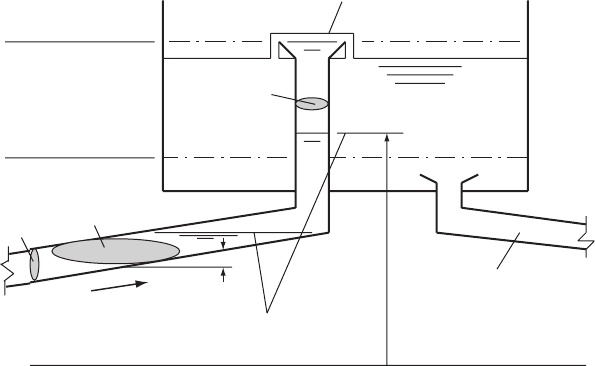
16.1 Vertical bellmouth
A simple and common configuration at the downstream end of a pumping
main is shown in Fig. 16.1. Normally flow enters the receiving reservoir via
the vertical bellmouth exiting at or above top water level (TWL) in the
tank. When water level in the chamber is below the discharge elevation
of the bellmouth it cannot influence static head of the pipeline system,
but rather system head is dictated by the bellmouth elevation.
Suppose flow reverses during a transient event with TWL below the
bellmouth exit elevation. The relatively small diameter and storage
capacity of the vertical pipe extending to the bellmouth will permit
head to fall quite rapidly within the pipe. Changing water level and
piezometric level H in the filling connection will be governed by
equations (16.1) and (16.2):
A
s
dH=dt ¼ AV and V þ g=aH ¼ Jþð16:1Þ
279
where A
s
is area of the air—water interface in the connection and A is
the rising main cross-sectional area. If water level reaches the rising
main level then:
A
s
¼ A=sin ðÞð16:2Þ
Depending upon the magnitude of a reversed velocity and its duration,
the vertical pipe may empty of water and air will start to enter the
upstream pipeline. Where the reversing flow is being used to expel sub-
stantial air pockets at upstream air valves or to refill a pressure vessel or
volumetric tank, the volumes required may be substantial. This can
lead to correspondingly large air volumes within the pipeline upstream
of the outfall and reduced piezometric level over downstream parts of
the system. A case study illustrating this aspect of behaviour may be
found in section 16.5 of this chapter. Such low pressures are undesirable
from a water quality standpoint as ingress of groundwater is a possibility.
If little or no refilling water is required then it is likely that the
duration of reversed flows will be modest and emptying of the vertical
pipe may not occur.
16.2 A tank or chamber of finite area
The case of a large reservoir effectively with surface area ¼1has been
considered in Chapter 6 on boundary conditions. When surface area is
280
Common horizontal datum
M
M
Piezometric level during filling
TWL
BWL or LDO
A
A
s
A
s
H
V
Drawoff
Piezometric levels
during reversed flow
q
Fig. 16.1. Vertical bellmouth filling arrangement
Pressure transients in water engineering
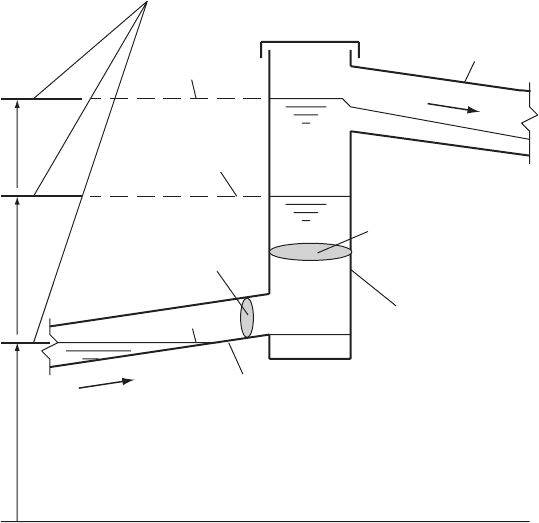
more modest, as where a tank is being filled or where flow is entering a
discharge chamber (Fig. 16.2), variations in level are more important.
In both of these cases the changing liquid surface level in the tank or
chamber has a direct influence upon the prevailing static head
operating. This boundary can be represented by the equation:
A
s
dH=dt ¼ VA
p
Q
out
ð16:3Þ
where A
s
is the surface area of the chamber, A
p
is the cross-sectional
area of the inlet pipe and Q
out
is the outflow (if any) from the tank.
If H > sewer invert then Q
out
¼ fnðHÞ and if H < sewer invert
Q
out
¼ 0:0. In addition there is the quasi-invariant value reaching
the tank at the time of interest along a Cþ characteristic, thus:
V þ g=aH ¼ Jþ
Setting H=t ¼ dH=dt and averaging over the time increment t
then:
A
s
H=t ¼ðV þ V
o
ÞA
p
=2 Q
out
281
M
M
M
A
s
A
p
Q
out
V
H
Common horizontal datum
Rising main
Minimum level
Manhole or
discharge chamber
While filling
or emptying
During steady
flow
Gravity sewer
Variable piezometric level
Fig. 16.2. Chamber connection with gravity flow outlet
Discharge conditions