El-Hawary M.E. Electrical Energy Systems
Подождите немного. Документ загружается.


326
© 2000 CRC Press LLC
∆
∆
=
∆
∆
Q
P
V
V
LJ
NH
θ
For the standpoint of computation, we use the rectangular form of the
power equations. We introduce
jijjijij
jijjijij
eBfGb
fBeGa
+=
−=
In terms of the a
ij
and b
ij
variables, we have
() ()
() ()
∑∑
∑∑
==
==
−=
+=
n
j
iji
n
j
ijii
n
j
iji
n
j
ijii
beafQ
bfaeP
11
11
To summarize the expressions for the Van Ness variables are given by:
2
2
2
2
iiiiii
iiiiii
iiiiii
iiiiii
iijiijijij
iijiijijij
VGPJ
VGPN
VBQL
VBQH
fbeaJN
ebfaLH
−=
+=
−=
−−=
+=−=
−==
()
diagonalsoffji
≠
A tremendous number of iterative techniques have been proposed to
solve the power flow problem. It is beyond the scope of this text to outline
many of the proposed variations. The Newton-Raphson method has gained a
wide acceptability in industry circles, and as a result there are a number of
available computer packages that are based on this powerful method and
sparsity-directed programming.
8.5 STABILITY CONSIDERATIONS
We are interested in the behavior of the system immediately following
a disturbance such as a short circuit on a transmission line, the opening of a line,
or the switching on of a large block of loads. Studies of this nature are called
transient stability analysis. The term stability is used in the sense of the ability

327
© 2000 CRC Press LLC
of the system machines to recover form small random perturbing forces and still
maintain synchronism. In this section we give an introduction to transient
stability in electric power system. We treat the case of a single machine
operating to supply an infinite bus. We do not deal with the analysis of the more
complex problem of large electric power networks with the interconnections
taken into consideration.
The Swing Equation
The dynamic equation relating the inertial torque to the net accelerating
torque of the synchronous machine rotor is called the swing equation. This
simply states
mN
2
2
⋅=
a
T
dt
d
J
θ
(8.37)
The left-hand side is the inertial torque, which is the product of the inertia (in
kg. m
2
) of all rotating masses attached to the rotor shaft and the angular
acceleration. The accelerating torque T
a
is in Newton meters and can be
expressed as
ema
TTT
−=
(8.38)
In the above, T
m
is the driving mechanical torque, and T
e
is the retarding or load
electrical torque.
The angular position of the rotor
θ
may be expressed as:
δωαθ
++=
t
R
(8.39)
The angle
α
is a constant that is needed if the angle
δ
is measured from an axis
different from the angular reference. The angle
ω
R
t is the result of the rotor
angular motion at rated speed. The angle
δ
is time varying and represents
deviations from the rated angular displacements. This is the basis for the new
relation
em
TT
dt
d
J
−=
2
2
δ
(8.40)
It is more convenient to make the following substitution of the dot notation:
2
2
dt
d
δ
δ
=

328
© 2000 CRC Press LLC
Therefore we have
em
TTJ
−=
δ
(8.41)
An alternative forms of Eq. (8.41) is the power form obtained by
multiplying both sides of Eq. (8.41) by
ω
and recalling that the product of the
torque T and angular velocity is the shaft power. This results in
em
PPJ
−=
δω
The quantity J
ω
is called the inertia constant and is truly an angular momentum
denoted by M (Js/rad). As a result,
ω
JM
=
(8.42)
Thus, the power form is
em
PPM
−=
δ
(8.43)
Concepts in Transient Stability
In order to gain an understanding of the concepts involved in transient
stability prediction, we will concentrate on the simplified network consisting of
a series reactance X connecting the machine and the infinite bus. Under these
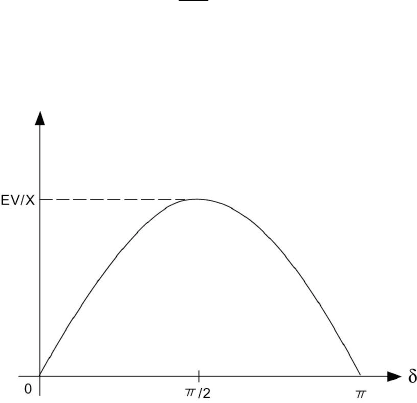
conditions the active power expression is given by:
δ
sin
X
EV
P
e
= (8.44)
This yields the power angle curve shown in Figure 8.3.
Figure 8.3 Power Angle Curve Corresponding to Eq. (8.44).

329
© 2000 CRC Press LLC
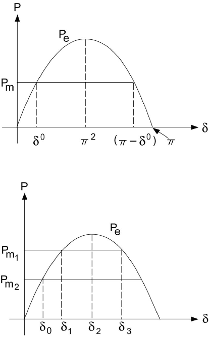
Figure 8.4 Stable and Unstable Equilibrium Points.
Figure 8.5 System Reaction to Sudden Change.
We assume that the electric changes involved are much faster than the
resulting mechanical changes produced by the generator/turbine speed control.
Thus we assume that the mechanical power is a constant for the purpose of
transient stability calculations. The functions P
m
and P
e
are plotted in Figure
8.4. The intersection of these two functions defines two values for
δ
. The lower
value is denoted
δ
0
; consequently, the higher is
π
-
δ
0
according to the symmetry
of the curve. At both points P
m
= P
e
; that is, d
2
δ
/dt
2
= 0, and we say that the
system is in equilibrium.
Assume that a change in operation of the system occurs such that
δ
is
increased by a small amount
∆
δ
. Now for operation near
δ
0
, P
e
> P
m
and d
2
δ
/dt
2
becomes negative according to the swing equation, Eq. (8.43). Thus
δ
is
decreased, and the system responds by returning to
δ
0
. We refer to this as a
stable equilibrium point. On the other hand, operating at
π
-
δ
0
results in a

330
© 2000 CRC Press LLC
system response that will increase
δ
and moving further from
π
-
δ
0
. For this
reason, we call
π
-
δ
0
an unstable equilibrium point.
If the system is operating in an equilibrium state supplying an electric
power
0
e
P
with the corresponding mechanical power input
0
m
P
, then
00
em
PP
=
and the corresponding rotor angle is
δ
0
. Suppose the mechanical power P
m
is
changed to
1
m
P
at a fast rate, which the angle
δ
cannot follow as shown in
Figure 8.5. In this case, P
m
> P
e
and acceleration occurs so that
δ
increases.
This goes on until the point
δ
1
where P
m
= P
e
, and the acceleration is zero. The
speed, however, is not zero at that point, and
δ
continues to increase beyond
δ
1
.
In this region, P
m
< P
e
and rotor retardation takes place. The rotor will stop at
δ
2
, where the speed is zero and retardation will bring
δ
down. This process
continues on as oscillations around the new equilibrium point
δ
1
. This serves to
illustrate what happens when the system is subjected to a sudden change in the
power balance of the right-hand side of the swing equation.
Changes in the network configuration between the two sides (sending
and receiving) will alter the value of X
eq
and hence the expression for the electric
power transfer. For example, opening one circuit of a double circuit line
increases the equivalent reactance between the sending and receiving ends and
therefore reduces the maximum transfer capacity
eq
X
EV
.
A Method for Stability Assessment
In order to predict whether a particular system is stable after a
disturbance it is necessary to solve the dynamic equation describing the behavior
of the angle
δ
immediately following an imbalance or disturbance to the system.
The system is said to be unstable if the angle between any two machines tends to
increase without limit. On the other hand, if under disturbance effects, the
angles between every possible pair reach maximum value and decrease
thereafter, the system is deemed stable.
Assuming as we have already done that the input is constant, with
negligible damping and constant source voltage behind the transient reactance,
the angle between two machines either increases indefinitely or oscillates after
all disturbances have occurred. Therefore, in the case of two machines, the two
machines either fall out of step on the first swing or never. Here the observation
that the machines’ angular differences stay constant can be taken as an
indication of system stability. A simple method for determining stability known
as the equal-area method is available, and is discussed in the following.

331
© 2000 CRC Press LLC
The Equal-Area Method
The swing equation for a machine connected to an infinite bus can be
written as
M
P
dt
d
a
=
ω
(8.45)
where
ω
= d
δ
/dt and P
a
is the accelerating power. We would like to obtain an
expression for the variation of the angular speed
ω
with P
a
. We observe that Eq.
(8.45) can be written in the alternate form
dt
d
d
M
p
d
a
=
δ
δ
ω
or
()
δωω
d
M
P
d
a
=
Integrating, we obtain
()
δωω
δ
δ
ω
ω
dP
M
d
a
∫∫
=
00
1
Note that we may assume
ω
0
= 0; consequently,
()
δω
δ
δ
dP
M
a
∫
=
0
2
2
or
()
21
0
2
=
∫
δ
δ
δ
δ
dP
Mdt
d
a
(8.46)
The above equation gives the relative speed of the machine with respect to a
reference from moving at a constant speed (by the definition of the angle
δ
).
If the system is stable, then the speed must be zero when the
acceleration is either zero or is opposing the rotor motion. Thus for a rotor that
is accelerating, the condition for stability is that a value of
δ
s
exists such that
()
0
≤
sa
P
δ

332
© 2000 CRC Press LLC
and
()
0
0
=
∫
δ
δ
δ
dP
s
a
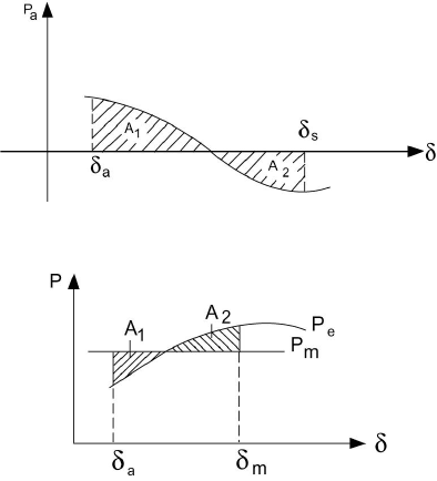
This condition is applied graphically in Figure 8.6 where the net area under the
P
a
-
δ
curve reaches zero at the angle
δ
s
as shown. Observe that at
δ
s
, P
a
is
negative, and consequently the system is stable. Also observe that area A
1
equals A
2
as indicated.
The accelerating power need not be plotted to assess stability. Instead,
the same information can be obtained form a plot of electrical and mechanical
powers. The former is the power angle curve, and the latter is assumed constant.
In this case, the integral may be interpreted as the area between the P
e
curve and
the curve of P
m
, both plotted versus
δ
. The area to be equal to zero must consist
of a positive portion A
1
, for which P
m
> P
e
, and an equal and opposite negative
potion A
2
, for which P
m
< P
e
. This explains the term equal-area criterion for
transient stability. This situation is shown in Figure 8.7.
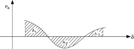
If the accelerating power reverses sign before the two areas A
1
and A
2
are equal, synchronism is lost. This situation is illustrated in Figure 8.8.The
area A
2
is smaller that A
1
, and as
δ
increases beyond the value where P
a
reverses
sign again, the area A
3
is added to A
1
.
Figure 8.6 The Equal-Area Criterion for Stability for a Stable System.
Figure 8.7 The Equal-Area Criterion for Stability.

333
© 2000 CRC Press LLC
Figure 8.8 The Equal-Area Criterion for an Unstable System.
Improving System Stability
The stability of the electric power system can be affected by changes in
the network or changes in the mechanical (steam or hydraulic) system. Network
changes that adversely affect system stability ca either decrease the amplitude of
the power curve or raise the load line. Examples of events that decrease the
amplitude of the power curve are: short circuits on tie lines, connecting a shunt
reactor, disconnecting a shunt capacitor, or opening a tie line. Events that raise
the load line include: disconnecting a resistive load in a sending area,
connecting a resistive load in a receiving area, the sudden loss of a large load in
a sending area, or the sudden loss of a generator in a receiving area. Changes in
a steam or hydraulic system that can affect stability include raising the load line
by either closing valves or gates in receiving areas or opening valves or gates in
sending areas.
There are several corrective actions that can be taken in order to
enhance the stability of the system following a disturbance. These measures can
be classified according to the type of disturbance – depending on whether it is a
loss of generation or a loss of load.
In the case of a loss of load, the system will have an excess power
supply. Among the measures that can be taken are:
1. Resistor braking.
2. Generator dropping.
3. Initiation along with braking, fast steam valve closures, bypassing
of steam, or reduction of water acceptance for hydro units.
In the case of loss of generation, countermeasures are:
1. Load shedding.
2. Fast control of valve opening in steam electric plants; and in the
case of hydro, increasing the water acceptance.
The measures mentioned above are taken at either the generation or the load
sides in the system. Measures that involve the interties (the lines) can be taken
to enhance the stability of the system. Among these we have the switching of
334
© 2000 CRC Press LLC
series capacitors into the lines, the switching of shunt capacitors or reactors, or
the boosting of power on HVDC lines.
Resistor braking relies on the connection of a bank of resistors in shunt
with the three-phase bus in a generation plant in a sending area through a
suitable switch. This switch is normally open and will be closed only upon the
activation of a control device that detects the increase in kinetic energy
exceeding a certain threshold. Resistive brakes have short time ratings to make
the cost much less than that of a continuous-duty resistor of the same rating. If
the clearing of the short circuit is delayed for more than the normal time (about
three cycles), the brakes should be disconnected and some generation should be
dropped.
Generator dropping is used to counteract the loss of a large load in a
sending area. This is sometimes used as a cheap substitute for resistor braking
to counteract short circuits in sending systems. It should be noted that better
control is achieved with resistor braking than with generator droppings.
To counteract the loss of generation, load shedding is employed. In
this instance, a rapid opening of selected feeder circuit breakers in selected load
areas is arranged. This disconnects the customer’s premises with interruptible
loads such as heating, air conditioning, air compressors, pumps where storage is
provided in tanks, or reservoirs. Aluminum reduction plants are among loads
that can be interrupted with only minor inconvenience. Load shedding by
temporary depression of voltage can also be employed. This reduction of
voltage can be achieved either by an intentional short circuit or by the
connection of a shunt reactor.
The insertion of switched series capacitors can counteract faults on ac
interties or permanent faults on dc interties in parallel with ac lines. In either
case, the insertion of the switched series capacitor decreases the transfer
reactance between the sending and receiving ends of the interconnection and
consequently increases the amplitude of the sine curve and therefore enhances
the stability of the system. It should be noted that the effect of a shunt capacitor
inserted in the middle of the intertie or the switching off of a shunt reactor in the
middle of the intertie is equivalent to the insertion of a series capacitor (this can
be verified by means of a Y-
∆
transformation).
To relieve ac lines of some of the overload and therefore provide a
larger margin of stability, the power transfer on a dc line may be boosted. This
is one of the major advantages of HVDC transmission.
8.6 POWER SYSTEM STATE ESTIMATION
Within the framework of an energy control center, there are three types
of real-time measurements:
335
© 2000 CRC Press LLC
•
Analog measurements that include real and reactive power flows
through transmission lines, real and reactive power injections
(generation or demand at buses), and bus voltage magnitudes.
•
Logic measurements that consist of the status of switches/breakers,
and transformer LTC positions.
•
Pseudo-measurements that may include predicted bus loads and
generation.
Analog and logic measurements are telemetered to the control center.
Errors and noise may be contained in the data. Data errors are due to failures in
measuring and telemetry equipment, noise in the communication system, and
delays in the transmission of data.
The state of a system is described by a set of variables, which at time t
0
contains all information about the system, which allows us to determine
completely the system behavior at a future time t
1
. A convenient choice is the
selection of a minimum set of variables, thus defining a minimum, but sufficient
set of state variables. Note that the state variables are not necessarily directly
accessible, measurable, or observable. Since the system model used is based on
a nodal representation, the choice of the state variables is rather obvious.
Assuming that line impedances are known, the state variables are the voltage
magnitudes and angles. This follows because all other values can be uniquely
defined once the state values are known.
State estimation is a mathematical procedure to yield a description of
the power system by computing the best estimate of the state variables (bus
voltages and angles) of the power system based on the received noisy data.
Once state variables are estimated, secondary quantities (e.g., line flows) can
readily be derived. The network topology module processes the logic
measurements to determine the network configuration. The state estimator
processes the set of analog measurements to determine the system state; it also
uses data such as the network parameters (e.g., line impedance), network
configuration supplied by the network topology, and sometimes, pseudo-
measurements. Since it not practical to make extensive measurements of
network parameters in the field, manufacturers data and one line drawings are
used to determine parameter values. This may then introduce another source of
error.
The mathematical formulation of the basic power system state
estimator assumes that the power system is static. Consider a system, which is
characterized by n state variables, denoted by
i
x , with i = 1, …, n. Let m
measurements be available. The measurement vector is denoted z and the state
vector is x. If the noise is denoted by v, then the relation between measurements
and states denoted by h is given by:
iii
vxhz
+=
)(
(8.47)
