El-Hawary M.E. Electrical Energy Systems
Подождите немного. Документ загружается.

285
© 2000 CRC Press LLC
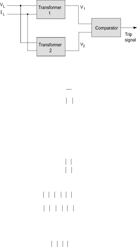
Figure 7.46 Schematic of Relay Comparator Circuit.
LL
L
L
L
Z
I
V
Z
φ
∠=
=
The transformers’ output voltages V
1
and V
2
are assumed to be linear
combinations of the input quantities
LL
IZVkV
111
+=
(7.51)
LL
IZVkV
222
+=
(7.52)
The impedances Z
1
and Z
2
are expressed in the polar form:
222
111
ψ
ψ
∠=
∠=
ZZ
ZZ
The comparator input voltages V
1
and V
2
are thus given by
()
LLL
ZZkIV
φψ
−∠+=
1111
(7.53)
()
LLL
ZZkIV
φψ
−∠+=
2222
(7.54)
C) Amplitude Comparison
The trip signal is produced for an amplitude comparator when
12
VV
≥
(7.55)
The operation condition is obtained as

286
© 2000 CRC Press LLC
()
() ()
[]
(
)
0coscos2
2
2
2
1222111
2
2
2
2
1
≤−+−−−+−
ZZZkZkZZkk
LLLL
φψφψ
(7.56)
This is the general equation for an amplitude comparison relay. The choices of
k
1
, k
2
, Z
1
, and Z
2
provide different relay characteristics.
Ohm Relay
The following parameter choice is made:
k
1
= kk
2
= -k
Z
1
= 0 Z
2
= Z
ψ
1
=
ψ
2
=
ψ
The relay threshold equation becomes
k
Z
XR
LL
2
sincos
≤+
ψψ
(7.57)
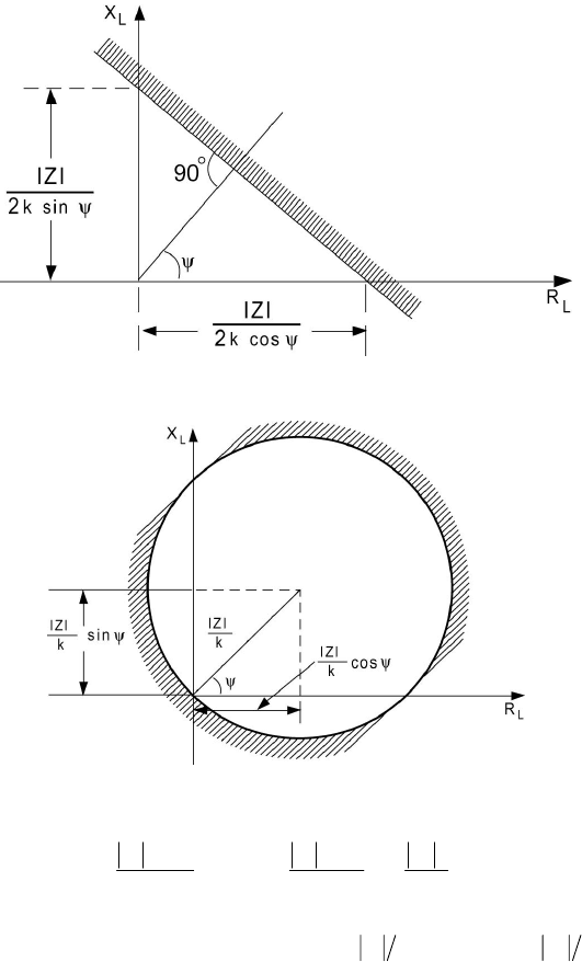
This is a straight line in the X
L
-R
L
plane as shown in Figure 7.47. The shaded
area is the restrain area; an operate signal is produced in the nonshaded area.
Mho Relay
The mho relay characteristic is obtained with the choice
k
1
= -kk
2
= 0
Z
1
= Z
2
= Z
ψ
1
=
ψ
2
=
ψ
2
2
22
sincos
k
Z
k
Z
X
k
Z
R
LL
≤
−+
−
ψψ
(7.58)
The threshold condition with equality sign is a circle as show in Figure 7.48.
Impedance Relay
Here we set
k
1
= -kk
2
= 0
Z
1
≠
Z
2
The threshold equation is
287
© 2000 CRC Press LLC
Figure 7.47 Ohm Relay Characteristic.
Figure 7.48 Mho Relay Characteristic.
2
2
2
2
1
2
1
sincos
k
Z
k
Z
X
k
Z
R
LL
≤
−+
−
ψψ
(7.59)
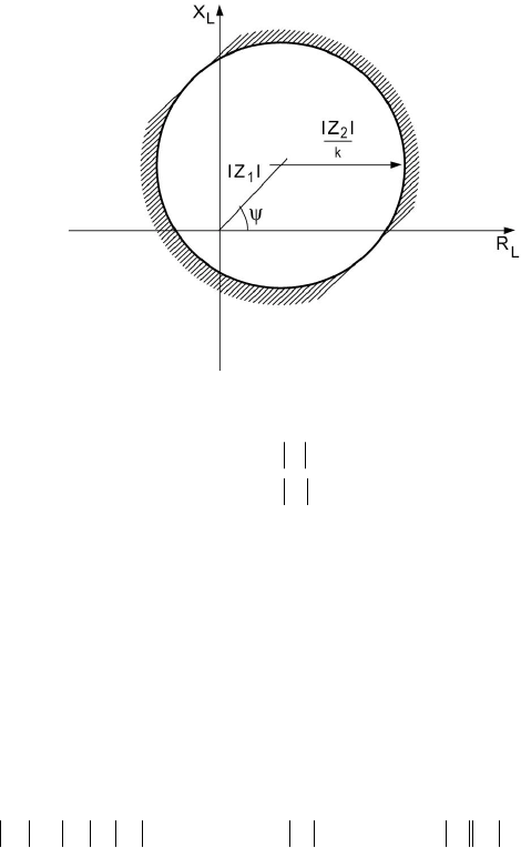
The threshold condition is a circle with center at
ψ
∠
kZ
1
and radius
kZ
2
as
shown in Figure 7.49.
Phase Comparison
Let us now consider the comparator operating in the phase comparison
mode. Assume that
288
© 2000 CRC Press LLC
Figure 7.49 Impedance Relay Characteristic.
222
111
θ
θ
∠=
∠=
VV
VV
Let the phase difference be defined as
21
θθθ
−=
A criterion for operation of the
±
90
°
phase comparator implies that
0cos
≥
θ
We can demonstrate that the general equation for the
±
90
°
phase comparator is
given by
() ()
[]
()
0coscoscos
121112121
2
22
≥−+−+−+
LLLLL
ZZZkZkZZkk
φψφψφψ
(7.60)
By assigning values to the parameters k
2
, k
3
, Z
1
, and Z
2
, different relay
characteristics such as the ohm and mho relays are obtained.
D) Distance Protection
Protection of lines and feeders based on comparison of the current
values at both ends of the line can become uneconomical. Distance protection
utilizes the current and voltage at the beginning of the line in a comparison
scheme that essentially determines the fault position. Impedance measurement
is performed using relay comparators. One input is proportional to the fault
current and the other supplied by a current proportional to the fault loop voltage.
289
© 2000 CRC Press LLC
A plain impedance relay whose characteristic is that shown in Figure
7.49. It will thus respond to faults behind it (third quadrant) in the X-R diagram
as well as in front of it. One way to prevent this is to add a separate directional
relay that will restrain tripping for faults behind the protected zone. The
reactance or mho relay with characteristics as shown in Figure 7.48 combines
the distance-measuring ability and the directional property. The term mho is
given to the relay where the circumference of the circle passes through the
origin, and the term was originally derived from the fact that the mho
characteristic (ohm spelled backward) is a straight line in the admittance plane.
Early applications of distance protection utilized relay operating times
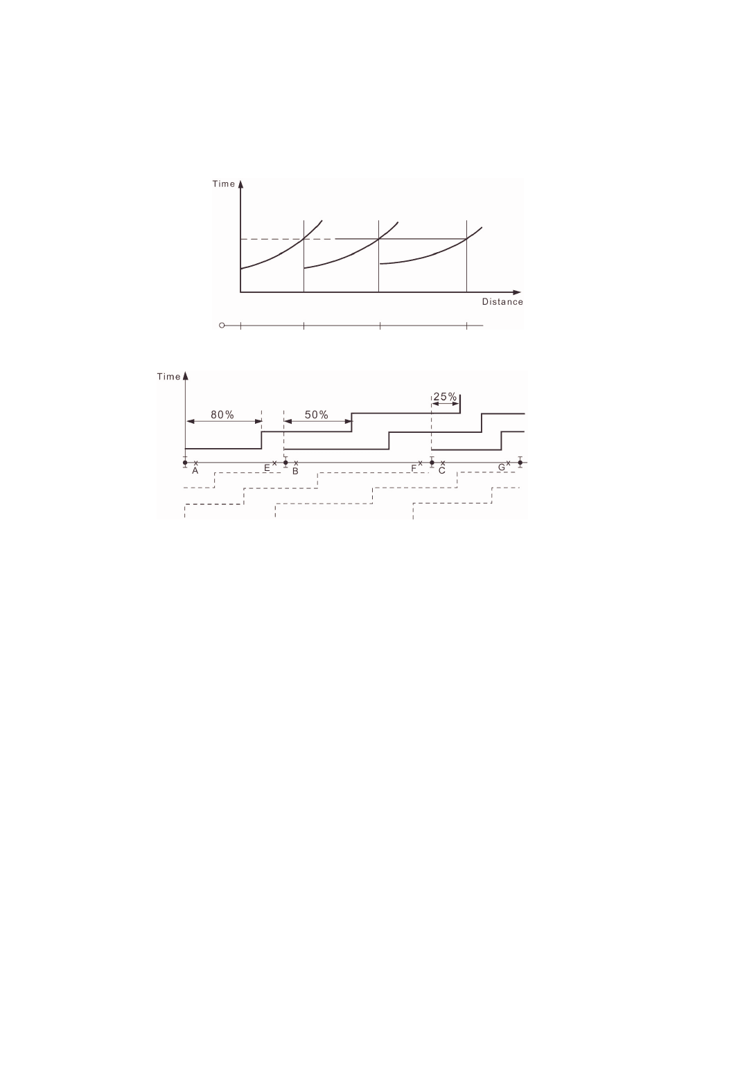
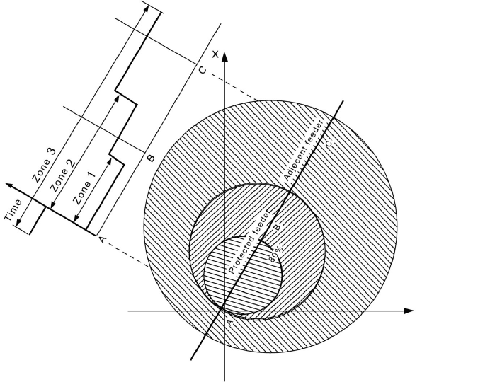
that were a function of the impedance for the fault. The nearer the fault, the
shorter the operating time. This is shown in Figure 7.50. Thishasthesame
disadvantages as overcurrent protection discussed earlier. Present practice is to
set the relay to operate simultaneously for faults that occur in the first 80 percent
of the feeder length (known as the first zone). Faults beyond this point and up to
a point midway along the next feeder are cleared by arranging for the zone
setting of the relay to be extended from the first zone value to the second zone
value after a time delay of about 0.5 to 1 second. The second zone for the first
relay should never be less than 20 percent of the first feeder length. The zone
setting extension is done by increasing the impedance in series with the relay
voltage coil current. A third zone is provided (using a starting relay) extending
from the middle of the second feeder into the third feeder up to 25 percent of the
length with a further delay of 1 or 2 seconds. This provides backup protection
as well. The time-distance characteristics for a three-feeder system are shown in
Figure 7.51.
Distance relaying schemes employ several relay units that are arranged
to give response characteristics such as that shown in Figure 7.52. A typical
system comprises:
1. Two offset mho units (with three elements each). The first
operates as earth-fault starting and third zone measuring relay, and
the second operates as phase-fault starting and third zone
measuring relay.
2. Two polarized mho units (with three elements each). The first unit
acts as first and second zone earth-fault measuring relay, and the
second unit acts as first and second zone phase-fault measuring
relay.
3. Two time-delay relays for second and third zone time
measurement.
The main difference between earth-fault and phase-fault relays is in the
potential transformer (P.T.) and C.T. connections, which are designed to cause
the relay to respond to the type of fault concerned.
290
© 2000 CRC Press LLC
Figure 7.50
Principle of Time-Distance Protection.
Figure 7.51
Time-Distance Characteristics of Distance Protection.
E) Power Line Carrier Protection
The overhead transmission lines are used as pilot circuits in carrier-
current protection systems. A carrier-frequency signal (30-200 kHz) is carried
by two of the line conductors to provide communication means between ends of
the line. The carrier signal is applied to the conductors via carrier coupling into
units comprising inductance/capacitor circuits tuned to the carrier signal
frequency to perform a number of functions. The carrier signals thus travel
mainly into the power line and not into undesired parts of the system such as the
bus bars. The communication equipment that operates at impedance levels of
the order of 50-150
Ω
is to be matched to the power line that typically has a
characteristic impedance is the range of 240-500
Ω
.
Power line carrier systems are used for two purposes. The first
involves measurements, and the second conveys signals from one end of the line
to the other with the measurement being done at each end by relays. When the
carrier channel is used for measurement, it is not practical to transmit amplitude
measurements from one end to the other since signal attenuation beyond the
control of the system takes place. As a result, the only feasible measurement
carrier system compares the phase angle of a derived current at each end of the
system in a manner similar to differential protection as discussed below.
Radio and microwave links have increasingly been applied in power
291
© 2000 CRC Press LLC
Figure 7.52 Characteristics of a Three-Zone Offset Mho-Relaying Scheme.
systems to provide communication channels for teleprotection as well as for
supervisory control and data acquisition.
7.14 COMPUTER RELAYING
In the electric power industry computer-based systems have evolved to
perform many complex tasks in energy control centers (treated in Chapter 8).
Research efforts directed at the prospect of using digital computers to perform
the tasks involved in power system protection date back to the mid-sixties and
were motivated by the emergence of process-control computers. Computer
relaying systems are now available. The availability of microprocessors used as
a replacement for electromechanical and solid-state relays provides a number of
advantages while meeting the basic protection philosophy requirement of
decentralization.
There are many perceived benefits of a digital relaying system:
1. Economics: With the steady decrease in cost of digital hardware,
coupled with the increase in cost of conventional relaying, it seems
292
© 2000 CRC Press LLC
reasonable to assume that computer relaying is an attractive
alternative. Software development cost can be expected to be
evened out by utilizing economies of scale in producing
microprocessors dedicated to basic relaying tasks.
2. Reliability: A digital system is continuously active providing a
high level of self-diagnosis to detect accidental failures within the
digital relaying system.
3. Flexibility: Revisions or modifications made necessary by
changing operational conditions can be accommodated by utilizing
the programmability features of a digital system. This would lead
to reduced inventories of parts for repair and maintenance
purposes.
4. System interaction: The availability of digital hardware that
monitors continuously the system performance at remote
substations can enhance the level of information available to the
control center. Postfault analysis of transient data can be
performed on the basis of system variables monitored by the digital
relay and recorded by the peripherals.
The main elements of a digital computer-based relay include:
1. Analog input subsystem
2. Digital input subsystem
3. Digital output subsystem
4. Relay logic and settings
5. Digital filters
The input signals to the relay are analog (continuous) and digital power system
variables. The digital inputs are of the order of five to ten and include status
changes (on-off) of contacts and changes in voltage levels in a circuit. The
analog signals are the 60-Hz currents and voltages. The number of analog
signals needed depends on the relay function but is in the range of 3 to 30 in all
cases. The analog signals are scaled down (attenuated) to acceptable computer
input levels (
±
10 volts maximum) and then converted to digital (discrete) form
through analog/digital converters (ADC). These functions are performed in the
“Analog Input Subsystem” block.
The digital output of the relay is available through the computer’s
parallel output port. Five-to-ten digital outputs are sufficient for most
applications. The analog signals are sampled at a rate between 240 Hz to about
2000 Hz. The sampled signals are entered into the scratch pad [random access
memory (RAM)] and are stored in a secondary data file for historical recording.
A digital filter removes noise effects from the sampled signals. The relay logic
program determines the functional operations of the relay and uses the filtered
sampled signals to arrive at a trip or no trip decision, which is then
communicated to the system.
The heart of the relay logic program is a relaying algorithm that is
293
© 2000 CRC Press LLC
designed to perform the intended relay function such as overcurrent detection,
differential protection, or distance protection, etc.
PROBLEMS
Problem 7.1
Consider the case of an open-line fault on phase B of a three-phase system, such
that
II
I
II
C
B
A
α
=
=
=
0
Find the sequence currents I
+
, I
-
, and I
0
.
Problem 7.2
Consider the case of a three-phase system supplied by a two-phase source such
that
0
=
=
=
C
B
A
V
jVV
VV
Find the sequence voltages V
+
, V
-
, and V
0
.
Problem 7.3
Calculate the phase currents and voltages for an unbalanced system with the
following sequence values:
20.0
30.0
50.0
0.1
0
0
−=
−=
=
−===
−
+
−+
V
V
V
jIII
Problem 7.4
Calculate the apparent power consumed in the system of Problem 7.3 using
sequence quantities and phase quantities.
Problem 7.5
The zero and positive sequence components of an unbalanced set of voltages are
866.05.0
2
0
jV
V
−=
=
+
The phase A voltage is
294
© 2000 CRC Press LLC
3
=
A
V
Obtain the negative sequence component and the B and C phase voltages.
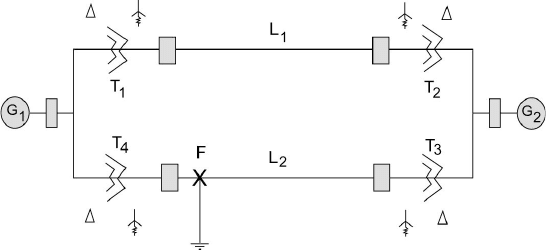
Problem 7.6
Obtain the sequence networks for the system shown in Figure 7.53 in the case of
a fault at F. Assume the following data in pu on the same base are given:
Generator G
1
: X
+
= 0.2 p.u.
X
-
= 0.12 p.u.
X
0
= 0.06 p.u.
Generator G
2
: X
+
= 0.33 p.u.
X
-
= 0.22 p.u.
X
0
= 0.066 p.u.
Transformer T
1
: X
+
= X
-
= X
0
= 0.2 p.u.
Transformer T
2
: X
+
=X
-
= X
0
= 0.225 p.u.
Transformer T
3
: X
+
= X
-
= X
0
= 0.27 p.u.
Transformer T
4
: X
+
= X
-
= X
0
= 0.16 p.u.
Line L
1
: X
+
= X
-
= 0.14 p.u.
X
0
= 0.3 p.u.
Line L
2
: X
+
= X
-
= 0.35 p.u.
X
0
= 0.6 p.u.
Figure 7.53 System for Problem 7.6.
Problem 7.7
Assume an unbalanced fault occurs on the line bus of transformer T
3
in the
system of Problem 7.6. Find the equivalent sequence networks for this
condition.
Problem 7.8
Repeat Problem 7.7 for a fault on the generator bus of G
2
.
Problem 7.9
Repeat Problem 7.7 for the fault in the middle of the line L
1
.
